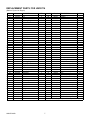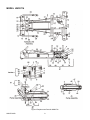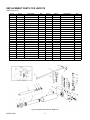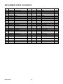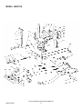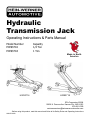
1
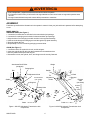
Hydraulic
Transmission Jack
Operating Instructions & Parts Manual
Model Number
HW93716
HW93718
Capacity
1/2 Ton
1 Ton
Made in North
America
HW93716
HW93718
SFA Companies ©2004
10939 N. Pomona Ave. Kansas City, MO 64153
816-891-6390
[email protected]
-Before using this product, read this manual and follow all its Safety Rules and Operating Instructions
HW93716-M0
TABLE OF CONTENTS
Warranty
Save These Instructions
Product Description
Specifications & Safety Instructions
Assembly
Operation
Maintenance
Troubleshooting
Replacement Parts
P2
P3
P3
P3
P4
P5
P5
P6
P6
TWO YEAR LIMITED WARRANTY
For a period of two (2) years from date of purchase, SFA Companies will repair or replace, at its option, without charge, any
of its products which fails due to a defect in material or workmanship, or which fails to conform to any implied warranty not
excluded hereby.
Performance of any obligation under this warranty may be obtained by returning the warranted product, freight prepaid, to
SFA Companies Warranty Service Department, 10939 N. Pomona Ave., Kansas City, MO 64153.
Except where such limitations and exclusions are specifically prohibited by applicable law:
(1) THE CONSUMER'S SOLE AND EXCLUSIVE REMEDY SHALL BE THE REPAIR OR REPLACEMENT OF DEFECTIVE
PRODUCTS AS DESCRIBED ABOVE.
(2) SFA COMPANIES SHALL NOT BE LIABLE FOR ANY CONSEQUENTIAL OR INCIDENTAL DAMAGE OR LOSS WHATSOEVER.
(3) THE DURATION OF ANY AND ALL EXPRESSED AND IMPLIED WARRANTIES, INCLUDING WITHOUT LIMITATION,
ANY WARRANTIES OF MERCHANTABILITY AND FITNESS FOR A PARTICULAR PURPOSE, IS LIMITED TO A PERIOD
OF TWO (2) YEARS FROM DATE OF PURCHASE.
Some states do not allow limitations on how long an implied warranty lasts, so the above limitation may not apply to you.
Some states do not allow the exclusion or limitation of incidental or consequential damages, so the above limitation or
exclusion may not apply to you. This warranty gives you specific legal rights, and you may also have other rights which vary
from state to state.
HW93716-M0
2
SAVE THESE INSTRUCTIONS
For your safety, read, understand, and follow the information provided with and on this jack. The owner and operator of this
equipment shall have an understanding of this jack and safe operating procedures before attempting to use. The owner and
operator shall be aware that use and repair of this product may require special skills and knowledge. Instructions and safety
information shall be conveyed in the operator's native language before use of this jack is authorized. If any doubt exists as
to the safe and proper use of this jack, remove from service immediately.
Inspect before each use. Do not use if there are broken, bent, cracked, or damaged parts (including labels). Any jack that
appears damaged in any way, operates abnormally or is missing parts, shall be removed from service immediately. If the
jack has been or suspected to have been subjected to a shock load (a load dropped suddenly, unexpectedly upon it),
immediately discontinue to use until jack has been checked by a Hein-Werner authorized service center. It is recommended
that an annual inspection be done by qualified personnel. Labels and Operator's Manual are available from manufacturer.
PRODUCT DESCRIPTION
The Hein-Werner Hydraulicc Transmission Jack is designed to be used as an aid in the removal and installation of automotive
and light truck transmissions, transfer cases and transaxles. It is intended for use under an overhead lift or in a garage pit.
SPECIFICATIONS
Model
Capacity Low Height High Height Forward Tilt Rearward Tilt Sideways Tilt
HW93716 1000 lbs
3 1/4"
26 1/4"
70º
20º
25 º L & R
HW93718 2000 lbs
10"
44"
40º
15º
10º L & R
SAFETY INSTRUCTIONS
BEFORE USE
1. Verify that the product and the application are compatible, if in doubt call Hein-Werner Technical Service (816) 891-6390.
2. Read the operator's manual completely and familiarize yourself thoroughly with the product, its components and recognize the potential hazards associated with its use before using this product.
3. Lower saddle fully.
5. Locate and remove air vent screw / oil filler plug. (For HW93718, This will help to release any pressurized air that may be
trapped within the reservoir.)
6. Ensure the oil level is just below the oil filler plug/screw hole.
7. Reinstall air vent screw / oil filler plug.
! WARNING
• Read and understand all printed material provided with and on this product before use.
• Do not exceed rated capacity.
• Ensure the center of gravity is centered on the saddle.
• Adequately support the vehicle before starting repairs.
• Use of this jack is limited to the removal, installation and transportation of transmissions, transfer cases and transaxles.
• Do not allow any part of your body under the load while jack is supporting a load.
• Use only the saddle assembly to lift. Never use any other part of the jack as a lifting surface.
• No alterations shall be made to this product.
• Only attachmens and/or adapters supplied by the manufacturer shall be used.
• This is a lifting and lowering device only. Transfer load immediately to appropriate support device for service or repair.
• Use the chain provided. If loaded jack must be moved, make certain that the load is secured by appropriate means,
is stable, is in lowest position, is moved over smooth, hard, surfaces, and that the lifting platform is level.
• Use only on hard, level, surfaces capable of supporting rated capacity loads.
• Failure to heed these markings may result in personal injury and/or property damage.
HW93716-M0
3
! ADVERTENCIA
• Leer, comprender, y seguir las instrucciónes antes de utilizar el aparato.
• El manual de instrucciónes y la información de seguridad deben estar comunicado en lengua del operador antes
del uso.
• No seguir estas indicaciónes puede causar daños personales o materiales.
ASSEMBLY
Familiarize yourself with the illustrations in the operator's manual. Know your jack and how it operates before attempting
to use.
MODEL HW93716
SWINGING ARMS (See Figure 1)
1. Locate the four bolts that are included in the transmission jack package.
2. Locate the four swinging arms included in the transmission jack package.
3. Align the hole of one swinging arm with one hole in the top plate assembly.
4. Insert one bolt through the swinging arm and through the top plate assembly.
5. Securely tighten the bolt.
6. Repeat steps 1-5 for the remaining swinging arms and bolts.
CHAIN (See Figure 1)
1. Locate the chain, the eyebolt, the hook, and the wingnut.
2. Insert the eyebolt through the roller that is attached to the attachment bar.
3. Securely fasten with the provided wingnut.
4. Ascertain the chain, the eyebolt, hook, and wingnut are all securely fastened.
Attachment Bar & Roller
(not shown)
Wedge
Swinging Arm
Saddle
Bolt
Chain
Tilt Adjustment Knob
Tilt
Adjustment
Knobs
Air Vent Screw
(not shown)
Saddle
Lifting Arm
Release
Valve
(not shown)
Lifting Arm
Oil Filler
Plug
(not shown)
Release Valve
Frame
Handle
Handle
Castor
Castor
Figure 2: HW 93718 Hydraulic Transmission Jack
Components
Figure 1: HW 93716 Hydraulic Transmission Jack
Components
HW93716-M0
4
ASSEMBLY contd...
MAINTENANCE
MODEL HW93718
WEDGES (See Figure 2)
1. Locate one of the four wedges.
2. Align the hole in the wedge with the hole in the saddle
assembly.
3. Secure with the nut, washer, and bolt.
4. Repeat steps 1-3 for the other three wedges.
IMPORTANT: Use only a good grade hydraulic jack oil.
Avoid mixing different types of fluid and never use brake
fluid, turbine oil, transmission fluid, motor oil, or glycerin.
Improper fluid can cause failure of the jack and the
potential for sudden and immediate loss of load.
ADDING OIL:
1. Lower saddle fully.
2. Remove the oil filler plug / air vent screw.
3. Fill with oil until just below the rim of the oil filler plug /
air vent screw.
4. Reinstall the oil filler plug / air vent screw.
CHAIN (See Figure 2)
1. Insert the bolt through one hole of the saddle
assembly (the holes that are lowest to the ground) if
accessible. If the assembly is extended, insert the
bolt through one hole of the adjustment plate.
2. Secure with washer and wingnut.
OPERATION
CHANGING OIL
1. Lower saddle fully.
2. Remove the oil filler plug / air vent screw.
3. Lay the jack on its side and drain the fluid into a
suitable container.
Follow the instruction for removal and installation of
transmission, transfer case or transaxle according to the
vehicle manufacturer's service manual.
NOTE: Dispose of hydraulic fluid in accordance with local
regulations.
4. Fill with oil until just below the rim of the oil filler plug /
air vent screw hole.
5. Reinstall the oil filler plug / air vent screw.
RAISE SADDLE ASSEMBLY:
1. Locate and close release valve by turning the valve
clockwise firmly.
2. Pump the handle until the load is contacted.
LUBRICATION
1. A periodic coating of light lubricating oil to pivot points,
axles, and hinges will help to prevent rust and assure
that wheels, castors, and pump assemblies move
freely.
2. When used on a daily basis, air pump model should
be internally lubricated before each use. Use only
good quality air tool lubricant.
IMPORTANT: Ensure the transmission is centered on
the jack. An off-center transmission could cause the
jack to tip over resulting in property damage or personal
injury.
LOWER SADDLE ASSEMBLY:
1. Slowly, gently, turn release valve counterclockwise to
lower load. No more than 1/2 full turn untill load is
fully lowered.
2. Secure the transmission to the jack with the chain.
3. For model HW93718, adjust the bolt to the desired
chain link. The transmission should be tightly
secured to the jack if proper adjustment is used.
CLEANING
Periodically inspect the ram for signs of rust or
corrosion. Clean as needed and wipe with an oily cloth.
NOTE: Never use sandpaper or abrasive material on
these surfaces!
STORAGE
When not in use, store the jack with ram fully retracted.
! WARNING
Be sure all tools and personnel are clear before lowering
load. Dynamic shock loads are created by quickly opening and closing the release valve as the load is being
lowered. The resulting overload may cause hydraulic
system failure.
HW93716-M0
5
To avoid crushing and related injuries:
NEVER work on, under or around a load
supported only by a jack. Immediately
transfer load to an appropriate work station.
TROUBLESHOOTING
Symptom
Possible Causes
Corrective Action
Jack will not lift load
• Release valve not tightly closed.
• Overload Condition
• Contact technical service
• Remedy overload condition
Jack bleeds off after lift
• Hydraulic unit malfunction
• Contact technical service
Jack will not lower after unloading
• Reservoir overfilled
• Ensure correct amount of oil
Oil leaking through filler plug
Poor lift performance
• Oil level is low
• Air trapped (Apply for HW93718
only)
• Ensure proper oil level
• With ram fully retracted, remove oil filler
plug to let pressurized air escape, then
reinstall oil filler plug.
Will not lift to full extension
• Fluid level low
• Ensure proper fluid level
REPLACEMENT PARTS
Not all components of the jack are replacement items, but are illustrated as a convenient reference of location and
position in the assembly sequence. When ordering parts, give Model number, parts number and description on pages 711. Call or write for current pricing: Phone:(888) 332-6419 or contact Hein-Werner Customer Support,
[email protected] or 10939 N. Pomona Ave. Kansas City, MO 64153
HW93716-M0
6
REPLACEMENT PARTS FOR HW93716
(Refer to Figure 3 on Page 8)
Item #
1
2
3
4
5
6
7
8
9
10
11
12
13
14
15
16
17
18
19
20
21
22
23
24
25
26
27
28
29
30
31
32
33
34
35
36
37
38
39
40
41
42
43
44
Part #
200003
201733
201789
201801
*203196
*203198
*203201
203265
203275
203349
*204842
209910
209970
210311
211013
211014
212227
212638
214599
*216143
217782
217898
218962
219531
220018
220861
220865
*221318
221365
221408
*221748
*224760
224867
224889
225518
226330
226357
226373
226375
226376
226738
227571
227576
227579
HW93716-M0
DESCRIPTION
Gasket
Plug
Lockwasher
Retaining Ring
Ball
Ball
Ball
Nut
Nut
Nut
Gasket
Pump Clip
Lockwasher
Plug
Plug
Spacer
Poppet
Bolt
Pin
O-Ring
Roll Pin
Roll Pin
Knob
Roll Pin
Retaining Ring
Chain, Eyebolt & Hook
Wing Nut
Screen
Handle Grip
Cotter Pin
Quad Ring
Heel Plate
Washer
Pin
Ram Ass'y.
Spacer
Pump Sleeve
Screw
Spring
Adapter
Lockwasher
Grommet
Handle Socket
Tube
QTY.
1
2
4
7
1
1
1
2
6
4
1
1
4
1
1
1
1
4
2
2
1
1
1
3
1
1
1
1
2
1
1
1
1
1
1
1
1
1
1
1
2
1
1
1
Item #
45
46
47
48
49
50
51
52
53
54
55
56
57
58
59
60
61
62
63
64
65
66
67
68
69
70
71
72
73
74
75
76
77
78
79
80
81
82
83
84
85
86
87
7
Part #
DESCRIPTION
227670
Pump Ass'y.
227671
Cylinder
227672
Piston
227673
Washer
227692
Tilt Pad Ass'y.
227715
Tilt Pin
227717
Washer
227718
Tilt Screw
227719
Pin
227720
Link
227721
Cradle
227723
Handle- R.H.
227724
Pivot Nut
227726
Tilt Screw
227766
Cotter Pin
227919
U-Cup Packing
228002
Cradle & Tilt Pad Ass'y.
228247
Pin
228570
Pin
228789
Handle- L.H.
231316
Plug & Gasket Ass'y.
231589
Bolt
231603
Caster
231638
Filler Plug & Vent Valve
231641
Oil Tank
231951
Side Plate Ass'y. - R.H.
231952
Side Plate Ass'y. - L.H.
231960
Spacer
233032
Screw
233033
Swing Arm Ass'y.
233037
Bolt
233143
Top Plate Ass'y.
233893
Chain & Terminal Ass'y.
*233917 Spring
233920
Release Stem
233977
Hand Knob
234005
Release Stem Ass'y.
234571
Cylinder
234665
Tank Nut
234666
Ram
234794
Unit Block
234983
Hydraulic Unit Ass'y.
234984
Bell Crank Ass'y.
* Sold Separately in 240521 Repair Kit
QTY
1
1
1
1
1
1
3
1
1
2
1
1
1
2
2
1
1
1
1
1
1
4
4
1
1
1
1
1
4
4
4
1
1
1
1
1
1
1
1
1
1
1
1
MODEL HW93716
Figure 3: Replacement Parts for HW93716
HW93716-M0
8
REPLACEMENT PARTS FOR HW93718
(Refer to Figure 4 )
Item #
2
3
4
5
6
7
8
9
10
11
12
13
14
15
16
17
18
19
20
21
22
Part #
245582
224867*
224760*
227919*
221748*
245586
245583
H6599200
H6014100
200003*
H0933000
245828
220021
220018
217898
233920
216143*
233917
212227*
233977
234005
Description
Ram
Back- Up Washer
Heel Plate
U-Cup
Quad Ring
Tank Nut
Cylinder
Oil Tank
Filler Screw
Washer
Handle Grip
Handle Assembly
Pin
Retaining Ring
Roll Pin
Release Stem
O Ring
Plastic Spring
Release Valve
Knob
Release Stem Ass'y
Qty.
1
1
1
1
1
1
1
1
1
1
1
1
2
2
1
1
1
1
1
1
1
Item #
23
24
25
26
27
28
29
30
31
32
33
34
35
36
37
38
39
40
41
42
43
44
Part #
H0267500*
H0218500*
H0301000*
H1185500
H1152000*
H2383500*
H0391000*
201733
226373
226375
226376
203196
245845
H0218000
261172
209910
248908
248909
245546
210311
245892
261169
* Sold Separately in 245892 Repair kit
Figure 4: Replacement Parts for HW93718
HW93716-M0
9
Description
Ball
Spring
Ball
Valve
Valve Seal
Spring
U-Cup
Expansion Plug
Adjusting Screw
Spring
Spring Cup
Ball
Bolt
Lock Washer
Unite Block
Piston Clip
Pump
Pump Guide
Socket Bracket
Pipe Plug
Repair Kit
Hyd.Unit w/o Handle
Qty.
1
1
1
1
1
1
1
1
1
1
1
1
4
4
1
1
1
1
1
1
REPLACEMENT PARTS FOR HW93718
Item #.
1*
2*
3*
4*
5*
6*
7*
8*
9*
10*
11
12
13
14
15
16
17
18
19
20
21
22
23
24
25
Part #
H0763000
H2224000
H5579300
H2672500
H2221000
H2524000
H2609500
H2207000
H2218500
H2222500
H6662100
H2205500
H2176000
H2213500
H2205000
H1896000
H6597900
H6599700
H5579600
H2176000
H2215500
H6660700
H2176000
H2213000
H2216000
Description
Adj. Angle Assembly
Adj. Stud Bracket
Washer
Hex Hd. Cap Screw
Yoke Clamp
Washer
Hex Nut
Adj. Yoke Rod
Adj. Yoke Bracket
Adjusting Screw
Chain Assembly
Saddle
Retaining Ring
Pin-Side Pivot
Saddle Holder
Hex Jam Nuts
Thrust Bearing
Pin-Forward Tilt
Washer
Retaining Ring
Pin-Forward Tilt
Adj.Screw Assembly Forward Tilt
Retaining Ring
Saddle Pivot Pin
Saddle Links
Qty.
2
2
6
6
2
4
4
2
1
4
1
1
1
1
1
2
2
1
2
2
1
1
2
1
2
Item #.
26
27
28
29
30
31
32
33
34
35
36
37
38
39
40
41
42
43
44
45
46
47
48
49
50
51
* Sold Separately in Attachment Kit # HW93249
HW93716-M0
10
Part #
H661600
245012
H2220500
H2223000
H2535900
H1103000
H2533500
203301
H0249000
245395
H6661800
H6599300
H2544500
H2608400
H2680600
H5579500
H2214500
H6599600
H0762000
H6662700
H6598900
H1308500
H0975000
H6665200
H2524500
H6665300
Description
Lift arm Assembly
Wedge
Adj Trans. Plate L.H.
Adj Trans. Plate R.H.
Bolt
Washer
Hex nut
Jam Nut
Bearings
Caster Assembly
Frame Assembly
Parallel Link spacer
Hex Jam Nut
Cotter Pin
Slotted Hex Nut
.063 Thick Washers
Pin-Side Anchor
Pin-Side Tilt
Adj. Screw Assembly Side Tilt
Rivet
Main Pivot Pin
Retaining Ring
Grease Fitting
Open Eye Bolt
Washer
Wing Nut
Qty.
1
4
1
1
8
8
8
4
4
4
1
1
2
1
1
4
1
1
1
1
1
2
1
1
1
1
MODEL HW93718
HW93716-M0
Figure 5: Replacement Parts for HW93718
11