1
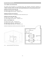
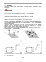
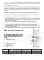
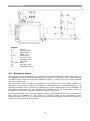
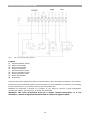
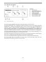
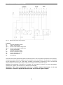
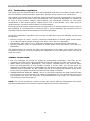
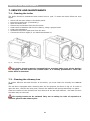
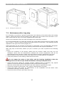
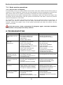
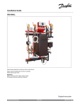
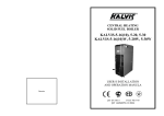
GAS/LIQUID FUELED STEEL BOILER ENERSAVE PLUS INSTALLATION AND SERVICE MANUAL VERSION: UPDATE: 2.1 14.10.2013 Contents 1. GENERAL INFORMATION ................................................................................... 3 1.1. Proper use of the appliance ................................................................................ 3 1.2. Safety warnings ................................................................................................ 3 1.3. Data label ........................................................................................................ 3 1.4. Document information ....................................................................................... 3 2. TECHNICAL FEATURES AND DIMENSIONS ......................................................... 4 2.1. Technical features ............................................................................................. 4 2.2. Function principle .............................................................................................. 4 2.3. Working medium ............................................................................................... 5 2.4. Dimensions ...................................................................................................... 6 2.5. Fuel ................................................................................................................. 9 3. BOILER MOUNTING ........................................................................................... 9 3.1. Transportation and delivery ................................................................................ 9 3.2. Boiler room .................................................................................................... 10 3.2.1. General requirements ................................................................................ 10 3.2.2. Boiler room dimensions .............................................................................. 11 3.3. Chimney ........................................................................................................ 12 3.4. Mounting the burner ........................................................................................ 13 4. INSTALLATION ................................................................................................ 14 4.1. Hydraulic connections ...................................................................................... 14 4.2. Expansion vessel ............................................................................................. 15 4.3. Safety features ............................................................................................... 16 4.4. Return temperature protection .......................................................................... 16 4.5. Filling the system ............................................................................................ 16 4.6. Connection diagrams ....................................................................................... 17 4.6.1. Central heating installation overview ........................................................... 17 5. ELECTRICAL CONNECTIONS ............................................................................ 18 5.1. General instructions......................................................................................... 18 5.2. Control panel functions .................................................................................... 18 5.2.1. EN-1 control panel .................................................................................... 18 5.2.2. EN-2S control panel................................................................................... 20 6. BOILER START-UP ........................................................................................... 22 6.1. Initial lighting checks ....................................................................................... 22 6.2. Start-up ......................................................................................................... 22 6.3. Checks to carry after initial start-up .................................................................. 22 6.4. Combustion regulation ..................................................................................... 23 7. SERVICE AND MAINTENANCE .......................................................................... 24 7.1. Cleaning the boiler .......................................................................................... 24 7.2. Cleaning the chimney box ................................................................................ 24 7.3. Maintenance after long stop .............................................................................. 25 7.4. Basic service procedures .................................................................................. 26 7.4.1. Service after overheating ........................................................................... 26 8. TROUBLESHOOTING ........................................................................................ 26 9. WARRANTY...................................................................................................... 27 GENERAL INFORMATION 1. GENERAL INFORMATION 1.1. Proper use of the appliance Before you make use of this appliance make sure you have read and fully understood the instructions included in this manual. The installation and use of the appliance must be performed according to the instructions indicated in this manual in combination with the current national safety regulations. The appliance is designed for use in pumped hot water central heating systems. Any other use is considered improper and is prohibited. THERMOSTAHL declines any responsibility for damages or injuries caused by improper use; in this case the risk is completely at the user’s responsibility. To ensure an efficient and flawless function of the appliance, it is strongly recommended that you have performed an annual service by a qualified technician. 1.2. Safety warnings All installation and maintenance procedures must be carried out by professional and authorized personnel, in compliance with the indications in the present manual and national regulations. Any failure to correctly install this appliance could cause damage or injuries! Do not make modifications to parts of the appliance, unless you have contacted the company and an authorized service contractor. Only original accessories and spare parts must be used to ensure correct and safe function. Make sure you respect the cleaning and maintenance procedures on the corresponding intervals. Failure to do so can cause malfunction to the appliance and possible damages. The boiler is design to function on the fuels indicated in the corresponding paragraph. Any other fuel is prohibited. Do not use explosive or flammable substances! Do not store such substances inside the boiler room. The working pressure varies according to the model. Make sure you use the appropriate water pressure. Working in a pressure higher than the one indicated in this manual is strictly prohibited and dangerous! 1.3. Data label The data label of the appliance is placed on the boiler’s side cover, on the external part. Make sure that it is properly placed and readable. On the label it is indicated the serial number and the manufacturing year of the appliance. 1.4. Document information This document is an integral and indispensable part of the product and must be retained in good condition by the user. Keep it in a safe place for future reference. If the appliance is sold or transferred to another person, this manual has to always follow the appliance and handed to the new user or installer. 3 TECHNICAL FEATURES AND DIMENSIONS 2. TECHNICAL FEATURES AND DIMENSIONS 2.1. Technical features The ENERSAVE boiler si made of steel, as a monobloc construction, with horizontal tubed heat exchanger and pressurized fire chamber. It functions on the principle of reversed flame, with three passes of burned gases: two passes in the combustion chamber and one pass in the exhaust tubes. The heat transfer is performed through radiation at the first two passes and through conduction at the third pass of the tubes. It is appropriate for light oil combustion and gas combustion. It is available as an independent boiler or as a unit with an integrated burner. It can also be combined with a hot water boiler hot water production. The boiler is designed for maximum working temperature of 90 oC. DESCIPTION OF COMPONENTS Steel boiler body with horizontal tube exchanger High efficiency stainless steel turbinators Removable rear smoke box with inspection cleaning door Front door insulated with refractory material, equipped with a flange for burner mounting and a flame inspection pipe Rockwool body insulation of 50 mm thickness Electrostatically painted external covers Control panel for electromechanical operation (optional) 2.2. Function principle ENP 20 – EN 300 Fig 1. EN 350 – EN 2500 Boiler function scheme The function of the boiler is is based on the counter-pressure that is created by the returnable flame in the combustion chamber and by the transmission of heat with radiation. The burned gases reverse their course at the bottom of the fire chamber, surrounding this way the flame, which does not get into immediate contact with the surrounding walls. The burned gases are then guided towards the smoke box through the fire tubes where the heat transfer is mainly through conductivity, and afterwards evacuated to the chimney. The smoke box is equipped with an inspection and cleaning door, which also actions as an explosion relief. The turbinators in the tubes create turbulance to the burned gases, so as to get into a continuous contact with the walls of the tubes and increase the heat transfer efficiency. 4 TECHNICAL FEATURES AND DIMENSIONS The resultis a complete and perfect combustion with a small excess of air, and uniform heat charge of the surfaces. The door has an insulation cord to ensure air-tight closing. The door is equipped with a flange for burner mounting and an inspection eye for flame inspection. 2.3. Working medium The ENP boiler is designed for function with water as working medium, with a maximum concentration in polypropylene glycole of 50%. The maximal temperature of the water is 95ºC. The minimal temperature of the return water is 65ºC for nominal decrease of temperature ∆t=20ºC in a device of heat performance. The boiler is appropriate for open and closed heating systems with maximal operation pressure 4 bars. The maximal operation pressure of the boilers with power bigger than 800 kW is 5 bar. The quality of the heating plant water is an important element for the performance of the system. The water that enters the heating plant must be clean, transparent and free from salts and chemical substances. It must be filtered, so as no quantity of sand or mud from the water supply comes into the boiler. The hardness of the water must be within permissible limits. In regions where the water is hard, it is necessary to use water softeners. Properties of the water for use: Appearance: clean-transparent Total hardness: Max 20ºf Free oxygen: Max 0,05 mg/lit Organic substances: Max 0,5 mg/lit ph: min 8,5 5 TECHNICAL FEATURES AND DIMENSIONS 2.4. Dimensions ENP 20-300 Type EN EN EN EN EN EN EN EN EN EN EN EN EN EN EN EN EN 20 30 40 50 60 70 80 90 100 120 140 160 180 200 220 250 300 A mm B mm C mm D mm E mm F mm L mm 700 700 700 700 790 790 790 790 1040 1040 1040 1040 1040 1040 1040 1040 1040 800 800 800 800 1015 1015 1015 1015 1240 1240 1240 1240 1240 1240 1240 1240 1240 595 595 595 595 685 685 685 685 950 950 950 950 950 950 950 950 950 410 460 560 660 610 710 810 910 910 1010 1110 1260 1010 1010 1260 1260 1510 425 425 425 495 495 495 495 495 540 540 540 540 640 640 640 640 640 530 530 530 530 635 635 635 635 635 655 655 655 790 790 790 790 790 700 800 900 1000 1010 1110 1210 1310 1350 1450 1550 1700 1600 1600 1850 1850 2100 6 T1-T2 inch 1 1 1 1 1 1 ¼” ¼” ¼” ½” ½” ½” 2” 2” 2” 2” 2 ½” 2 ½” 2 ½” 2 ½” 2 ½” 2 ½” 3” T3 mm T4 mm T5 inch T6 inch 139 139 139 139 159 159 159 159 193 193 193 193 244 244 244 244 293 106 106 106 106 125 125 125 125 146 146 146 146 160 160 160 160 160 ½” ½” ½” ½” ½” ½” ½” ½” ½” ½” ½” ½” 1” 1” 1” 1” 1” ½” ½” ½” ½” ¾” ¾” ¾” ¾” 1” 1” 1 ¼” 1 ¼” 1 ½” 1 ½” 1 ½” 1 ½” 1 ½” TECHNICAL FEATURES AND DIMENSIONS ENP 350-2500 Type ENP ENP ENP ENP ENP ENP ENP ENP ENP ENP ENP ENP ENP ENP ENP ENP ENP ENP ENP ENP ENP ENP 350 400 450 500 550 600 650 700 750 800 900 1000 1100 1200 1300 1400 1500 1650 1800 2000 2300 2500 A mm B mm C mm D mm E mm F mm L mm T1-T2 inch T3 mm T4 mm T6 inch 1290 1290 1290 1290 1290 1290 1290 1540 1540 1540 1540 1540 1540 1540 1540 1540 1540 1540 1940 1940 1940 1940 1545 1545 1545 1545 1545 1545 1545 1935 1935 1935 1935 1935 1935 1935 1935 1935 1935 1935 2235 2235 2235 2235 1170 1170 1170 1170 1170 1170 1170 1350 1350 1350 1350 1350 1350 1350 1350 1350 1350 1350 1850 1850 1850 1850 1270 1270 1520 1520 1770 1770 2020 1520 1520 1770 2020 2020 2270 2270 2270 2520 2520 2770 2100 2100 2600 2600 750 750 750 750 750 750 750 960 960 960 960 960 960 960 960 960 960 960 1250 1250 1250 1250 980 980 980 980 980 980 980 1000 1000 1000 1000 1000 1000 1000 1000 1000 1000 1000 1500 1500 1500 1500 1850 1850 2150 2150 2450 2450 2700 2450 2450 2700 2900 2900 3150 3150 3150 3550 3550 3800 3200 3200 3700 3700 DN 80 DN 80 DN 100 DN 100 DN 100 DN 100 DN 125 DN 125 DN 125 DN 125 DN 125 DN 125 DN 150 DN 150 DN 150 DN 150 DN 150 DN 150 DN 150 DN 150 DN 200 DN 200 343 343 343 343 343 343 343 343 343 395 395 395 395 395 485 485 485 485 580 580 580 580 220 220 220 220 220 220 220 270 270 270 270 270 270 270 270 270 270 270 380 380 380 380 2” 2” 2” 2” 2” 2” 2” 2 ½” 2 ½” 2 ½” 2 ½” 2 ½” 2 ½” 2 ½” 2 ½” 2 ½” 2 ½” 2 ½” 3” 3” 3” 3” 7 TECHNICAL FEATURES AND DIMENSIONS TECHNICAL DATA Type Nominal power Backpressure Fire chamber volume Heated surface Pressure drop Water content Weight Pmax Effici ency Mcal/h kW mm H2O lit m2 (Δt=150oC) mmH2O lit kg bar % ENP 20 20 23 2..4 24 1,2 20 46 158 4 91,5 ENP 30 30 35 2..4 31 1,6 20 57 179 4 91,5 ENP 40 40 47 2..4 39 1,9 20 70 197 4 91,5 ENP 50 50 58 2..4 47 2,4 30 81 220 4 91,5 ENP 60 ENP 70 60 70 69 81 4..6 4..6 56 64 2,6 3,1 40 50 117 128 271 308 4 4 91,5 91,5 ENP 80 80 93 6..10 76 4,5 75 138 416 4 91,5 ENP 100 ENP 120 100 120 116 140 6..10 6..10 144 161 4,9 6,0 80 90 246 282 439 465 4 4 91,5 91,5 ENP 140 140 163 8..15 179 6,7 100 305 502 4 91,5 ENP 160 160 186 10..20 205 7,2 120 326 538 4 91,5 ENP 180 ENP 200 180 200 209 233 10..20 10..20 206 206 6,7 7,2 100 120 400 427 687 747 4 4 93 93 ENP 220 220 256 10..20 263 8,0 150 471 782 4 93 ENP 250 250 291 10..20 263 8,7 150 523 805 4 93 ENP 300 300 349 20..30 320 10,3 180 607 885 4 93 ENP 350 ENP 400 350 400 407 465 20..30 20..30 423 423 13,4 13,4 200 200 782 753 1518 1529 4 4 93 93 ENP 450 450 522 20..30 539 15,8 220 809 1587 4 93 ENP 500 500 581 20..30 539 15,8 220 809 1598 4 93 ENP 550 550 637 20..30 577 16,8 250 848 1621 4 93 ENP 600 600 698 20..30 577 18,3 250 877 1690 4 93 ENP 650 650 756 30..40 692 20,7 300 947 1817 4 93 ENP 700 ENP 750 700 750 814 872 30..40 30..40 872 872 23,3 24,0 350 350 1180 1250 2250 2390 5 5 93 93 ENP 800 800 930 30..40 1052 25,4 350 1325 2510 5 93 ENP 900 900 1047 30..40 1052 1365 2620 5 93 1000 1163 30..40 1098 26,3 22.73333 3333 27,1 400 ENP 1000 400 1390 2710 5 93 ENP 1100 1100 1279 30..40 1280 29,8 400 1440 2880 5 93 ENP 1200 1200 1396 30..40 1280 31,0 400 1495 2980 5 93 ENP 1300 1300 1453 30..40 1280 33,2 400 1550 3090 5 93 ENP 1400 1400 1628 30..40 1390 34,5 400 1640 3220 5 93 ENP 1500 1500 1740 30..40 1390 36,8 400 1740 3360 5 93 ENP 1650 1650 1919 30..40 1550 39,0 400 1830 3650 5 93 ENP 1800 ENP 2000 1800 2000 2093 2326 40..60 40..60 1940 1940 39,7 40,5 450 450 2178 2140 4455 4570 5 5 93 93 ENP 2300 2300 2675 40..60 2185 47,1 450 2464 5220 5 93 ENP 2500 2500 2887 40..60 2785 54,5 450 2600 5800 5 93 8 BOILER MOUNTING 2.5. Fuel The ENP is designed for function with the following fuels: 1. Natural Gas, according to DIN 4756 and 4788, with lower calorific power 8.500 kcal/Nm3. The delivery conditions of natural gas to the burner are stabilized by the Norm for natural gas I 6-98, for gas with low pressure (p=500 mmCA) 2. Light oil fuel EL, according to DIN 4755 and 4787, with a viscosity of 4,5 cSt at 20oC and lower calorific power 9.900 kcal/kg. 3. Light oil fuel with lower calorific power 9.650 kcal/kg. No other fuel than the ones mentioned should be used with this boiler! If you wish to use an alternative fuel, please contact the manufacturer. When liquid fuel is used, pay attention at the following: When filling the fuel tank, avoid any water or dust entering together with the fuel in the tank. When the room temperature of the location where the boiler is mounted is lower than 0oC, it is recommended the use of a pre-heater. 3. BOILER MOUNTING 3.1. Transportation and delivery The boiler is delivered complete with the metal covers, well packaged. The loading and unloading of the boiler must be performed with a forklift or a crane. A special hook is provided on the upper part of the boiler for lifting. The boiler is heavy. Do not try to lift by hands or other unsuitable equipment. Danger of injury! Perform all moves with extreme attention and care. Remove the boiler packaging with attention. Keep the packaging material away from chidren since it can be dangerous. After having unpacked everything, make sure that the appliacne is intact and undamaged. In case of doubt do not use the appliance and inform the supplier. The ENP boiler is delivered with the following equipment already fitted and mounted: Boiler steel body Rockwool insulation mounted on the boiler body and tightened with plastic tapes Metal covers mounted on the boiler body Turbinators positioned inside the fire tubes The following accessories are positioned inside the boiler body. Remove them carefully by opening the middle door. Cleaning tools Drainage valve Burner sealing cord Control panel (optional) In the documentation folder you will find: Technical manual Warranty leaflet Declaration of conformity 9 BOILER MOUNTING 3.2. Boiler room 3.2.1. General requirements The boiler must be installed in a special and separate room. This room must be chosen so that it offers easy access for fuel transport, air supply and exhaust gas evacuation. The doors of the boiler room must be metallic, open outwards, and have at least 0,9 m width. The boiler installation is prohibited in rooms with extensive dust, dangerous gases, and moist spaces. For the correct boiler function it is necessary that the boiler room has openings for natural ventilation and combustion air supply. It is recommended that two different openings are used for this purpose, positioned on opposite walls and diagonally to ensure good air circulation. The cross section of the openings can be estimated by the following formula: F=Q*8 /1000 Where F=Surface of the opening in cm² (with grid) (without grid by receiving 2/3 of the F) Q=Heating power of the boiler in kcal/h The boiler room must be provided with a drainage channel. All safety devices must be connected to this channel. The boiler room must have an appropriate fire extinguishing system, according to the regulations in force. In case that the building is designed with a fire alarm system, a smoke detector must be positioned on top of every boiler. The fuel storage is prohibited in the boiler room. If so, the storage must be separated from the boiler with a non-flammable wall, and proper distanced from the boiler. Fig 2. Boiler room ventilation and air supply 10 BOILER MOUNTING 3.2.2. Boiler room dimensions The boiler must be placed on a horizontal plane, with adequate mechanical resistance to support the boiler’s weight. The boiler must be positioned in the room in such a way so that it is easily accessible from all the sides. The following dimensions are recommended (see Fig 3): Distance from the front wall (N): For boilers up to 100 kW – minimum 1,5 m For boilers bigger than 100 kW – minimum 2 m Distance from the rear wall (L): Appropriate distance for maintenance access. Minimum 0,6 m. Distance from side walls (M): For boiler up to 300 KW – minimum 0,6 m For boilers bigger than 300 kW – minimum 1 m Boiler room height (H): For For For For boilers up to 70 kW – minimum 2 m boilers 70 to 230 kW – minimum 2,4 m boiler 230 to 400 kW – minimum 3 m boiler bigger than 400 kW – minimum 3,5 m Distance between two boilers (P) must be at least 1m. Fig 3. Recommended boiler room dimensions 11 BOILER MOUNTING 3.3. Chimney The chimney installation must supply sufficient draught, air tightness and protection against condensation. The appropriate chimney installation is very important for the boiler’s efficient and safe function! The chimney must be positioned if possible in the interior of the building. It must be vertical, with no changes in the direction. The cross-section of the chimney can be round or rectangular. If the chimney is installed in the exterior, it must be insulated. The horizontal part connecting the boiler’s chimney pipe with the vertical chimney must have maximum length 2 m. If this distance is bigger, it is recommended to have a 15-30o inclination upwards. The connection with the boiler’s chimney pipe must be air-tight. The chimney must be equipped with a cleaning door at its base. Also cleaning doors are recommended where there are changes in direction and ash can be accumulated. Tactical cleaning is recommended (every 3 months) for efficient boiler function. A chimney terminal must be installed at the end of the chimney for protection against weather effects and foreign objects entrance. In areas with strong winds a special anti-downdraught terminal is recommended. The chimney height must exceed the roofline by at least 1 m. If there are other obstacles positioned on the roof, the chimney height must exceed them by at least 1 m. If there are multiple chimneys, minimum distance between them is 0,3m. Each boiler should be connected to an independent chimney. Connection of multiple boilers to the same chimney is not recommended. Fig 4. Chimney distances Fig 5. Chimney connection 12 BOILER MOUNTING 3.4. Mounting the burner The ENP boilers are overpressure boilers and it is necessary to take into account the static pressure of counter-pressure in the combustion chamber to select the proper burner. The dimensions of the flange on the boiler door for mounting the burner as well as of the support screws are according to DIN 4789. The part of the fuel pipes, which are connected to the burner must have sufficient length and must be flexible, in order to allow the opening of the boiler door. The gap around the boiler flange is filled by fireproof ceramic material. The supply of fuel must be adjusted at the nominal power of the boiler, by selection of the appropriate atomizer. For the mounting of the burner on the boiler, you must take care of the following: The burner must be well fixed on the special flange of the boiler. The four screws must be fastened well, so that the burner is not loose on the boiler. The sealing flange of the burner ensures insulation from combustion gas leaks. Take care that it does not break. The injection neck of the burner must be deep enough in the boiler, so that its edge reaches deeper than the plate that carries the tubes. The burners with long injection neck are more proper for boilers made of steel. The burner must be positioned horizontally and parallel to the combustion chamber. The position of the burner must be correctly aligned in connection with the center of the combustion chamber. In this way a uniform flame is developed and a better distribution of the thermal load is ensured. The door must fit well on the sealing cord in order not to have combustion gas leaks. The space between the injection neck of the burner and the door of the boiler must be insulated with fireproof material. The fireproof material of the door of the boiler must be replaced with new material, if it gets damaged during the use. The burner neck must penetrate inside the combustion chamber in a way that the entire heat exchange surface of the fire chamber is performed uniformly by the exhaust gas. If the neck of the burner is of very small size, the flame goes directly to the fire tubes, a fact that results in excessive increase of the thermal strain of the boiler. Legend 1. Burner 2. Burner mounting flange 3. Door insulation with fire proof material 4. Insulation around the injection neck of the burner 5. Boiler door 6. Ceramic insulation flange 7. Sealing cord 8. Burner injection neck 9. Tube 10. Boiler front plate Dimensions D(Фmm) L1(mm) L2(mm) Tab1. ENP 20-50 ENP 60-90 ENP 100-160 ENP 180-300 ENP 350-700 ENP 800-1800 ENP 2000-4000 114 140-150 15-20 139 150-170 25-35 159 190-220 40-50 193 250-280 60-80 273 360-500 80-100 356 500-600 120-200 394 800-1000 200-400 Burner mounting dimensions 13 INSTALLATION 4. INSTALLATION 4.1. Hydraulic connections ENP 20-300 Legend T1 Boiler outlet T2 Boiler inlet T3 Chimney connection T5 Drainage valve T6 Safety connection ENP 350-2500 Legend T1 Boiler outlet T2 Boiler inlet T3 Chimney connection T6 Safety connection The boiler is intended for connection with a closed expansion vessel network. The boiler is intended for maximum working temperature 90 oC and maximum pressure 3 bar. The expansion vessel must be connected on the return line. The discharge valve must be connected through a pipe to the drainage. If a connection pipe is not used, it must be sealed before water fill! 14 INSTALLATION Legend 1. 2. 3. 4. 5,7,8. 6. 9. 10. 11,13,15. 12. 14. Burner Control panel Manometer Safety kit Safety valve Air relief valve Drainage valve Ball valve Pump One-way valve Expansion vessel 4.2. Expansion vessel The ENP boiler is recommended to be connected with closed expansion vessel. The volume of the expansion vessel is calculated according to the quantity of the water in the installation and the static height. When choosing the expansion vessel, it should never be chosen marginal size, but a size greater. The expansion vessel should be connected at the return line of the boiler. Before the installation, the pressure inside the expansuion vessel should be regulated according to its geometrical height from the point of its position up to the highest point of the installation. If this height is lower than 8 m, then the pressure is adjusted at 0,8 bar. If the boiler room is on a rooftop, the pressure on the tank should be adjusted at 0,5 bar. The automatic filling valve must be installed next to the expansion tank and it is adjusted so that, when the installation is cool, there is a pressure equal to the geometrical height mentioned above plus 2 m. In areas where high-pressure distributing networks are present, a pressure reducing gear must be placed. 15 INSTALLATION 4.3. Safety features The boiler equipment includes a safety kit, which shall be connected to the corresponding safety connection pipe. The kit consists of a safety valve, an air relief valve and a thermomanometer. Additional safety equipment can be mounted on the outlet line, at a distance less than 1,5 m from the boiler. Boiler power 50 kW 100 kW 200 kW 350 kW 580 kW 870 kW Fig 6. Safety valve ½’’ ¾’’ 1’’ 1 ¼’’ 1 ½’’ 2’’ Boiler safety kit 4.4. Return temperature protection For the correct function of the boiler and for protection against condensation and corrosion it is very important to ensure steady temperature at the return of the boiler of at least 55oC. This can be ensured by installing a recirculation pump between the boiler outlet and return (see connection diagrams). An alternative variation is by installing at the return of the boiler a three-way thermostatic valve. 4.5. Filling the system After completing all the hydraulic connections, the circuit may be filled with water. After filling the system, open the radiators air valves to get rid of the air in the installation. Verify that the installation pressure is according to the technical feature of the boiler. The pressure must be verified through the boiler’s manometer. An additional manometer should be installed on the cold water inlet to verify the cold pressure, at the lowest point of the installation, at a point close to the boiler. The whole installation must remain under nominal pressure for at least 10 minutes. During this period, check that all the connections are tight and there are no water leakages. Make sure that during this period no pressure drop appears. After firing the boiler, make sure the network functions properly at working temperature and pressure. The hardness of the mains water supply affects the boiler’s life span. It is recommended to use a water softener if water hardness exceeds 15 of. Do not fill the system at the working pressure! When the boiler will be heated, the water pressure will raise. Filling pressure must be at least 1 bar lower than working pressure! 16 INSTALLATION 4.6. Connection diagrams 4.6.1. Central heating installation overview Legend 1. Boiler 2. Burner 3. Burner filter 4. Pump 5. Fuel tank 6. Water-level indicator 7. Tank ventilator 8. Tank alimentation 9. Tank plug 10. Fuel valve for the burner 11. Electromagnetic oil valve 12. Water return 13. Outlet water collector 14. Return water collector 15. 16. 17. 18. 19. 20. 21. 22. 23. 24. 25. 26. 27. 17 Water filter Radiators Radiators valves Expansion vessel Automatic water filler Burner thermostat Pump thermostat 4-way mixing valve Control panel External temperature sensor Chimney Chimney cleaning door Drainage ELECTRICAL CONNECTIONS 5. ELECTRICAL CONNECTIONS 5.1. General instructions All electrical connection must be performed by an authorized professional, in conformity with the local regulations and the indications of this manual. Connections must be done according to norms EN 60529 and EN 60335-1, and protection norms IP 40 and IP 44. All wiring must be waterproof insulated. Exposed cables should be protected within plastic channel. The main electrical supply of the boiler must be connected to an independent safety of max 16A. The boiler room lighting must be on a separate circuit. THERMOSTAHL is not responsible for accidents or malfunctions caused by wrong or bad electrical connections. 5.2. Control panel functions 5.2.1. EN-1 control panel Legend: 1. Thermometer 2. Burner thermostat 3. Safety thermostat 4. Pump thermostat 5. General ON/OFF switch 6. Burner indication lamp 7. Pump indication lamp Fig 7. EN-1 control panel The general switch ON/OFF interrupts the electrical supply to all the devices. The burner thermostat interrupts the burner function when the preset boiler temperature has been reached. It is recommended that this temperature is set between 70-90oC. This temperature should never be set below 55oC. Please note that various pellet burners might have different electrical connections. In any case follow the manufacturer’s instructions. The pump thermostat starts the circulation pump function at the preset temperature. It is recommended that this temperature is set around 45-55oC. The safety thermostat will interrupt the fan function if the boiler temperature reaches above 95oC. If so, it needs to be reset manually by unscrewing the plastic cover. The burner and pump indication lamps follow the function of the corresponding devices. The control panel offers the possibility to connect with a room thermostat. When the room thermostat contact opens, the burner function stops. 18 ELECTRICAL CONNECTIONS Fig 8. EN-1 control panel wiring diagram Legend: M General ON/OFF switch TS Safety thermostat TB Burner thermostat TP Pump thermostat L General function lamp LB Burner indication lamp LP Pump indication lamp TR Room thermostat PE Grounding Unscrew the control panel back plate to have access to the connection terminals in the interior. Connect the main electrical supply to the terminals 1,2,3 as indicated. The burner is connected to the terminals 9,10,11 and the pump to the terminals 4,5,6. Between the terminals 7,8 there is a jumper. If you want to connect a room thermostat, remove the jumper and connect it to these two terminals. Attention: The room thermostat must be a simple contact interruptor. It is not allowed to connect a digital thermostat with an electrical signal output! 19 ELECTRICAL CONNECTIONS 5.2.2. EN-2S control panel Legend: 1. Thermometer 2. Burner thermostat TR-1 3. Burner thermostat TR-2 4. Safety thermostat 5. Pump thermostat 6. General ON/OFF switch 7. Burner indication lamp 8. Pump indication lamp Fig 9. EN-2S control panel The general switch ON/OFF interrupts the electrical supply to all the devices. The burner thermostat TR-1 controls the stage-one function of the burner. When the preset temperature is reached, the stage-one stops function and the burner goes automatically to stage-two function. When the preset temperature of the TR-2 thermostat is reached, the burner function is interrupted. It is recommended that this temperature is set between 7090oC. This temperature should never be set below 55oC. Please note that various pellet burners might have different electrical connections. In any case follow the manufacturer’s instructions. The pump thermostat starts the circulation pump function at the preset temperature. It is recommended that this temperature is set around 45-55oC. The safety thermostat will interrupt the fan function if the boiler temperature reaches above 95oC. If so, it needs to be reset manually by unscrewing the plastic cover. The burner and pump indication lamps follow the function of the corresponding devices. The control panel offers the possibility to connect with a room thermostat. When the room thermostat contact opens, the burner function stops. 20 ELECTRICAL CONNECTIONS Fig 10. EN-2S control panel wiring diagram Legend: M General ON/OFF switch TS Safety thermostat TB-1 Burner thermostat-stage one TB-2 Burner thermostat-stage two TP Pump thermostat L General function lamp LB Burner indication lamp LP Pump indication lamp TR Room thermostat PE Grounding Unscrew the control panel back plate to have access to the connection terminals in the interior. Connect the main electrical supply to the terminals 1,2,3 as indicated. The burner is connected to the terminals 9,10,11,12. First stage comand is connected to terminal 11 (F1) and second stage comand to terminal 12 (F2). Pump is connected to the terminals 4,5,6. Between the terminals 7,8 there is a jumper. If you want to connect a room thermostat, remove the jumper and connect it to these two terminals. Attention: The room thermostat must be a simple contact interruptor. It is not allowed to connect a digital thermostat with an electrical signal output! 21 BOILER START-UP 6. BOILER START-UP 6.1. Initial lighting checks Before you start the boiler, make the following checks: Check that all the hydraulic connections and make sure they are tight. Make sure there is no leakage or moisture on the pipes or other equipment. Make sure that the connection with the chimney is air-tight and the chimney installation is properly made. Check that the controller bulbs are well inserted and secured in the boiler’s case. Make sure that the pressure in the network is correct. Check that the boiler pump and the central heating pumps function properly. Make sure that the connection with the expansion vessel is correct and the expansion volume is sufficient for the boiler. No valves should be installed between the boiler and the expansion vessel. Make sure the boiler’s separation valves are open. Make sure that there is sufficient air supply and natural ventilation in the boiler room. Do not store inflammable materials or fuel close to the boiler! Before you light the boiler make sure the boiler room is clear and safe. 6.2. Start-up To correctly start up the ENP boiler, follow the next steps: Make sure the control panel switch is set to OFF and the burner is stopped. Make sure there is fuel in the fuel tank, or gas supply. Make sure all the connections guiding fuel to the burner are tight. Turn ON the control panel and the burner. Turn the burner thermostat ON so that the burner will start function. Follow the burner instruction in order to correctly start and set the burner. Wait several minutes until the flame develops. Check the shape and color. Check the quality of the flame. 6.3. Checks to carry after initial start-up During the first start-up you need to carefully check the air-tightness of all the connections, especially the doors and the connection with the chimney. Check that the thermostats function properly and devices operate accordingly. Wait for the boiler to reach the preset temperature and make sure the burner stops properly and the flame falls down. Check the temperature and pressure rise in the network. Make sure it is according to the indications. Check if there is any water leakage in the network. After a burning cycle is completed, check the situation inside the boiler. If the walls are too black, it means that there is insufficient air supply. If there is condensation forming on the boiler walls, it means that the pump operation starts at a low temperature. Make sure you set the pump according to the indications and you install a return temperature protection system as indicated. It is prohibited to light the boiler with inflammable or explosive liquids. 22 BOILER START-UP 6.4. Combustion regulation The flame from the burner must be thin and longitudinal and should not reach the side walls of the fire chamber (nozzle projection angle=60º, possibly 45º for power over 140 Mcal/h). The loading of the boiler with an atomizer smaller than the one that corresponds to the normal heat value supply of the boiler is not recommended. The function of ENP boilers is possible up to 70% of their nominal heating output without any significant reduction on the outlet temperature of the exhaust gases. Output below 70% is not allowed, since there may be caused harmful corrosions due formation of condensations. If during the performance measurements the temperature of exhaust gases is too low, there is the possibility of increasing the by removing two or more turbinators (as required) from the fire tubes that are placed at the bottom of the front tube plate. During the combustion regulation of the burner on ENP boiler type the following values must be reached: Burning of light oil: CO2= 12-13%, maximum temperature of burned gases outlet=220ºC up to 180 kW and for boilers of bigger size 240ºC, soot rate=0-1 Bacharach. Gas burning: CO2 max=0,05 %, maximum temperature of burned gases outlet=240ºC Burning of heavy crude oil: temperature of burned gases outlet 220-260ºC, soot rate=0-1 Bacharach. The measurements are carried out after the temperature of the water of the boiler has been increased to 80-90ºC. For built chimneys the temperature of burned gases outlet must be at least 150-170ºC. GENERAL SUGGESTIONS: CO: This indicates the excess air supply for good quality combustion. The more the air increases, the CO% value reduces and the more the air reduces the CO% value increases. SOOT RATE (according to Bacharach): This number indicates that in the exhaust gases there are solid particles. If this number exceeds 2 on BH scale, you should check the atomizer for possible defects or unsuitability for the burner and the boiler (make, type, and diffusion angle). Generally, the BH number reduces by increasing the pressure of the valve. In this case you should be careful because the fuel supply increases. TEMPERATURE OF EXHAUST GASES: This is a value that expresses the heat losses through the chimney to the environment. The higher the temperature is, the greater the heat loss is and therefore the lower the efficiency. If the temperature is very high, you should reduce the quantity of the consumed oil. NOTE: The current regulations of each country may require different adjustments from those that have already been done and this requires observance of other parameters. 23 SERVICE AND MAINTENANCE 7. SERVICE AND MAINTENANCE 7.1. Cleaning the boiler The boiler should be maintained and cleaned once a year. To clean the boiler follow the next steps: Switch off the main switch in the boiler panel. Disconnect the burner (if necessary). Open the boiler door. Remove the turbinators from the fire tubes. Clean the fire chamber and the fire tubes by using a proper brush. Clean the turbinators. Assemble the pieces again and close the door. Connect the burner again (if you had disconnected it). Fig 11. Cleaning the boiler The boiler function must be stopped before cleaning! Make sure all the devices are stopped, and the boiler has cooled down. It is strictly prohibited to clean the boiler while in function! 7.2. Cleaning the chimney box To ensure efficient and safe function of the boiler, you must clean the chimney box once a year. The ash box is equipped with a cleaning door for this purpose, as shown in Fig 12. In order to open the door, unscrew the wing nuts, remove the washers and springs that keep it in place. Clean the interior of the chimney box and remove all the ash and residues. Put back the door the same way as removed. The springs must not be omitted! They act as safety in order of explosion of exhaust gases in the chimney box. 24 SERVICE AND MAINTENANCE Fig 12. Cleaning the chimney box 7.3. Maintenance after long stop It is necessary to perform a general maintenance and cleaning of the boiler after the heating season. Check the doors and the sealing cord. Make sure the contact with the boiler is airtight. Check that the door is correctly regulated and closes tight. Remove the turbinators from the heat exchanger and check their condition. It is recommended that you clean the chimney box of the boiler and the chimney pipes at least once a year, in order to assure efficient and safe function of the boiler. The cleaning interval depends on the type of fuel used (oil/gas, etc.) Clean thoroughly all the surfaces of the boiler as described in the corresponding paragraph. Also clean the chimney box, and all the chimney parts where ash might be deposited. After long stop of the boiler, before you put in function you need to perform the following checks: Check the condition of the electric cables and the sensors. Make sure they are not damaged. Check that the thermometer indicates the correct temperature and all the thermostats function properly. Make sure the bulbs are properly positioned in the case. Make a general check of the chimney and make sure it is clean and free of obstacles. Verify the pressure in the heating network and the boiler. Do not empty the water of the boiler and the heating installation after the heating season! It will corrupt all the installation and especially the boiler. Check that all the valves are working properly. Replace them if necessary. Pay special attention so that all the safety equipment of the boiler functions properly! Make sure all the ball valves of the boiler and other relative equipment are open. Check the function of the pumps. They might be blocked after long stop. Check that there have been no modifications to the installation and the boiler room (ventilation openings, chimney, doors). Check the burner function and clean from dust. 25 TROUBLESHOOTING 7.4. Basic service procedures 7.4.1. Service after overheating If overheating occurs, the safety valves of the boiler must open. Make sure the boiler pump is working. In case of blackout, the burner will stop operation and the temperature will soon fall. Open some valves of the system if necessary to decrease the boiler temperature faster. All safety devices must lead to drainage! After overheating, make sure that all the water from the safety devices has drained, and the system has filled with cold water. Check the pressure and the temperature of the boiler. At overheating, the safety thermostat will activate, and cut electrical supply to the burner. In that case, you need to manually reset the safety thermostat and put the system back in function. Unscrew the plastic cover of the safety thermostat and press the switch. Put the plastic cover back. Verify the causes of the overheating! If it happens again, check the installation and function of the pumps and safety devices! 8. TROUBLESHOOTING Problem The lamps of the control panel do not light The boiler does not reach set temperature Cause - no electrical supply to the lamp - the control panel is not connected to electricity - lamp defect - electric cable defect - fan blocked - air passages are blocked - boiler is not cleaned - incorrect boiler start-up - insufficient water in the system - too big pump debit - boiler under dimensioned - bad quality fuel used - insufficient chimney draught High temperature in the boiler, but low temperature at the radiators Condensation formation in the fire chamber - too high hydraulic resistance in the heating network - thermostatic mixing valve is connected wrong - too big boiler power - too low return temperature in the boiler - fuel with excessive humidity Smoke coming out of the doors - The fan does not function or it makes a lot of noise - set temperature reached - disconnected by safety thermostat - capacitor/motor defect - bad electrical connection of the fan boiler doors not regulated defect sealing cord of the door insufficient chimney draught too high air supply by the fan 26 Solution - check/replace the lamp - connect to electricity - check/replace the cabels - check/replace the fan, check the function of the fan regulator and thermostat - clean the air passages - clean the boiler - start the boiler correctly - fill the system - regulate the pump speed - change the fuel used - check/clean the chimney - increase the pump speed - check/replace the mixing valve - load less fuel in the chamber - install a return protection system/thermostatic valve - change the fuel used - regulate the doors so that the sealing cord stays tight - check/replace the sealing cord - check/clean the chimney - reduce the air speed - correct boiler function - reset manually - check/replace the fan - check the electrical connection of the fan WARRANTY 9. WARRANTY 1. Warranty duration is 3 years for all boiler parts under pressure, 1 year for other electromechanical equipment. The warranty period starts from the date of installation, but no longer than 120 days from the day of purchase. 2. The warranty covers costs of replacing parts that have been proved to be defect, and any work that is connected with replacing these parts. Costs related to removing defect parts or products, transportation, etc. are not covered by the producer’s warranty. 3. The producer will not accept to cover warranty terms in case of the following: 4. Maltreating the product and bad conditions of transportation and loading-unloading. 5. Wrong installation, failing to apply the directions given in the manual. 6. Improper use of the product. 7. Damages that have been cause by using improper fuels, with dimensions or characteristics different from those described in the manual. 8. Damages from freezing if not necessary measures are taken against anti-freezing. 9. Incident of explosion due to use of impropriate chemical substances. 10. Electrical shocks that may harm electrical parts of the appliance. 11. 12. Warranty is only valid if the installation is performed by a professional installer, authorized by the producer, according to the local legislation and the instructions of this manual. 13. Warranty does not cover function problems or damages that are caused by bad chimney installation, failing to respect the instruction of this manual and local legislation. 14. Warranty is not valid if the boiler cleaning, maintenance and service intervals are not respected and the directions given are not followed. 15. Warranty is not valid if the maintenance is not performed by an authorized professional according the instructions given and at the time intervals given. 16. Warranty does not cover costs related to emergency incidents like: earthquake, fire, electrical blackout, robbery. 17. Warranty is not valid if the hardness of the water is over the allowed limits and no water softening protection is installed. 18. The warranty is not transferable in case of reselling or replacing the product. A new warranty should be accorded to the new user. 27 THERMOSTAHL ROMANIA SISTEME TERMICE S.R.L. DRUMUL OSIEI 57-59, sector 6 Bucuresti 062395, Romania www.thermostahl.ro