1
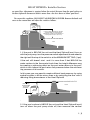
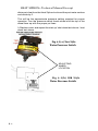
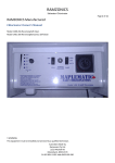
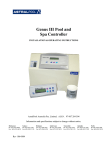
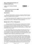
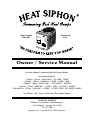
Made in Latrobe
Since 1983
Pennsylvania
U.S.A.
Owner / Service Manual
For Heat Siphon® Swimming Pool Heat Pump Models:
Discontinued Models:
(220Volt - 1 Phase - 60 Hz ONLY) - SX3.25HP , SX5HP
(220Volt - 1 Phase - 50/60 Hz) - 2.25HP , 3.25HP , 5.0HP
(220Volt - 1 Phase - 50 Hz ONLY) - SX3.25HP50 , SX5HP50
(220Volt - 3 Phase - 50/60 Hz) - 3.25HP3 , 5HP3 , SX3.25HP3 , SX5HP3
(380/460 Volt - 3 Phase - 50/60 Hz) - 2.25HPX , 3.25HPX , 5HPX , SX3.25HPX , SX5HPX
New Models: ALL C Series And Z Series Heat Siphon Models
ALL RIGHTS RESERVED
Publisher: United States ThermoAmp Inc.
1223 Walnut St. , Latrobe, PA. 15650
724-537-3500
Copyright 1994, 1998, United States ThermoAmp Inc.
HEAT SIPHON® Technical Manual Excerpt
Adjustment of the Water Pressure Switch
Below are pictures of the water pressure switch and its location in your Heat Siphon:
Fig 4.2 - Water Pressure Switch Location in Control Box
Compressor Run Capacitor
Contactor
Capacitor
Mounting
Strap
Fan Run
Capacitor
24 volt
Transformer
Water
Pressure
Switch
5 minute
Time
Delay
Low Pressure Switch
Thermostat
High Pressure Switch
Heat Siphon’s exclusive FULL FLOW Titanium heat exchanger has a minimal pressure drop
and requires NO SPECIAL PLUMBING arrangement. It should be considered as just another length of PVC pipe in your pool filtration system.
LOCATION: Connect Heat Siphon® in the pool pump discharge (return)
line DOWNSTREAM of all filters and pool pumps, and UPSTREAM
of any electranator chlorinators or chemical pumps.
SIZE: All Heat Siphon®’s have 1.5 “ x 2” fittings for connection to the
pool or spa filtration piping which will accept 1.5” schedule 40 PVC
pipe directly or 2” SCH 40 PVC pipe with a 2” PVC coupling. The
in-line water pressure drop produced by Heat Siphon is less than 1.5
psi at 30 GPM.
Only one Heat Siphon® adjustment may be required at installation. On some models of
the Heat Siphon® a gas heater type water pressure sensing switch is used to detect flow
rather than direct flow measurement. The switch prevents Heat Siphon® operation with
I2 - 2
HEAT SIPHON® Installer Section
no water flow. Adjustment is required when the vertical distance from the pool surface to
the Heat Siphon® thermostat knob is more than a few feet above or below pool level .
To correct this condition, DISCONNECT ALL ELECTRICAL POWER. Remove the knob and
cover to the control box and adjust the switch as follows.
HEAT
SIPHON
IF UNIT IS WELL ABOVE POOL WATER
YOU MAY NEED TO CREATE BACK
PRESSURE TO TRIP THE FLOW SWITCH
(install eyeball sockets in return lines)
PUMP
POOL
1. If the pool is BELOW the unit and the Heat Siphon® won’t turn on
with the pool pump, turn the pressure switch adjustment thumb wheel to
the right until the top of the switch is at the MINIMUM SETTING (1 psi).
If the unit still doesn’t start and it is more than 2 feet BELOW the
water surface to the thermostat knob then the height difference may
be creating a siphoning effect as the pool water returns to the pool,
which in turn lowers the pool return line pressure below the minimum
trip pressure of this switch.
In this case you may need to create sufficient back pressure by using
eyeball sockets in all the return lines or by restricting the flow with a
reducing fitting downstream of the Heat Siphon®
DISTANCE
FROM KNOB
TO POOL
SURFACE
POOL
HEAT
SIPHON
PUMP
.
2. If the pool surface is ABOVE the unit and the Heat Siphon® won’t
turn off when the pool pump shuts off, then measure the vertical
I-3
HEAT SIPHON® Technical Manual Excerpt
distance in feet from the Heat Siphon knob and the pool water surface
and divide by 2.
This will be the approximate pressure setting required for proper
operation. Turn the pressure switch thumb wheel until the top of the
wheel lines up with the proper psi lines.
3. Replace cover and repeat the start up/ shut down test above. / shut
down test above.
Fig 4-1(a) New Style
Water Pressure Switch
ADJUSTING
WHEEL
LOCATION
Fig 4-1(b) Old Style
Water Pressure Switch
I4 - 4