1
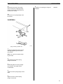
Service Manual
Trucks
Group
721–500
Front Springs
VN,VHD
PV776-TSP141989
Foreword
The descriptions and service procedures contained in this manual are based on designs and methods studies carried out up to August 2000.
The products are under continuous development. Vehicles and components produced
after the above date may therefore have different specifications and repair methods.
When this is believed to have a significant bearing on this manual, supplementary service bulletins will be issued to cover the changes.
The new edition of this manual will update the changes.
In service procedures where the title incorporates an operation number, this is a reference to an S.R.T. (Standard Repair Time).
Service procedures which do not include an operation number in the title are for general information and no reference is made to an S.R.T.
The following levels of observations, cautions and warnings are used in this Service
Documentation:
Note: Indicates a procedure, practice, or condition that must be followed in order to
have the vehicle or component function in the manner intended.
Caution: Indicates an unsafe practice where damage to the product could occur.
Warning: Indicates an unsafe practice where personal injury or severe damage to the
product could occur.
Danger: Indicates an unsafe practice where serious personal injury or death could occur.
Volvo Trucks North America, Inc.
Greensboro, NC USA
Order number: PV776-TSP141989
© 2000 Volvo Trucks North America, Inc., Greensboro, NC USA
All rights reserved. No part of this publication may be reproduced, stored in
retrieval system, or transmitted in any forms by any means, electronic, mechanical, photocopying, recording or otherwise, without the prior written
permission of Volvo Trucks North America, Inc..
Contents
General .................................................................................................... 3
Front Spring Suspension ....................................................................... 3
Specifications .........................................................................................
Front Springs .........................................................................................
VN ........................................................................................................
VHD .....................................................................................................
5
5
5
6
Tools ........................................................................................................ 7
Special Tools ......................................................................................... 7
Design and Function ............................................................................. 9
Front Springs ........................................................................................... 9
Front Spring Suspension, Exploded View ........................................... 10
VN Models ......................................................................................... 10
Front Spring Suspension, Exploded View ........................................... 11
VHD Models ...................................................................................... 11
Front Hangers .................................................................................... 12
Rear Hangers .................................................................................... 13
Shackles and Pins ............................................................................. 14
Wedges and Spacers ........................................................................ 15
Bump Stop ......................................................................................... 15
U-bolts ............................................................................................... 16
Shock absorber ................................................................................. 16
Service Procedures .............................................................................
Front Spring, Replacement .................................................................
VN Models .........................................................................................
Front Spring, Replacement .................................................................
VHD Models ......................................................................................
Front Shock Absorber, Replacement ..................................................
Front Shock Absorber Bracket, Replacement .....................................
Front Shackle/Pin, Replacement .........................................................
Front Spring Bushing, Replacement ...................................................
Front Spring Height, Checking ............................................................
Cab Lean, Checking ............................................................................
Front Spring U-bolt Torque, Adjustment ..............................................
Front Spring Rear Hanger, Replacement ............................................
Front Spring Front Hanger, Replacement ...........................................
17
17
17
19
19
20
20
21
21
23
24
24
25
26
Feedback
Operation Numbers
1
2
Group 72 Front Springs
General
General
Front Spring Suspension
This service information describes the design, function, operation, and service procedures for the front springs and associated components used on the Volvo VN/VHD
series vehicles.
The front spring suspension supports the weight of the vehicle and isolates it from vibrations caused by irregularities in the road surface. It transmits the force of that weight
to the front wheels through the springs and the front axle. The major components of
the front spring suspension are the springs, spring hangers, and the shock absorbers.
Associated components consist of the shackles, spring pins, U-bolts, and wedges.
3
4
Group 72 Front Springs
Specifications
Specifications
Front Springs
VN
Springs
Length
.............................................................................................................................................. 1335 mm (52.5 in.)
Type/Axle Load
Parabolic ............................................................................................................................... 5.5 metric ton (12,000 lb.)
Parabolic ............................................................................................................................... 5.7 metric ton (12,500 lb.)
Parabolic ............................................................................................................................... 6.0 metric ton (13,200 lb.)
Parabolic ............................................................................................................................... 6.7 metric ton (14,600 lb.)
Parabolic ............................................................................................................................... 7.3 metric ton (16,600 lb.)
Shock Absorber
Manufacturer ........................................................................................................................................................... Sachs
Spring Bushing
Axial play (max) ....................................................................................................................................... 5mm (.197 in.)
Torque Requirements
Spring pin pinch bolts
.......................................................................................................... 85 ± 15 Nm (63 ± 11 ft-lb)
U-bolts .............................................................................................................................. 420 ± 50 Nm (311 ± 37 ft-lb)
Spring hanger mounting bolts .......................................................................................... 200 ± 30 Nm (148 ± 22 ft-lb)
Shock absorber mounting bolts
....................................................................................... 275 ± 45 Nm (204 ± 33 ft-lb)
Rubber spring spacer ......................................................................................................... 110 ± 15 Nm (81 ± 11 ft-lb)
5
Group 72 Front Springs
Specifications
VHD
Springs
Length
.............................................................................................................................................. 1335 mm (52.5 in.)
Type/Axle Load
Parabolic ............................................................................................................................... 5.7 metric ton (12,500 lb.)
Parabolic ............................................................................................................................... 6.7 metric ton (14,600 lb.)
Parabolic & Multi-Leaf .......................................................................................................... 7.5 metric ton (16,500 lb.)
Multi-Leaf .............................................................................................................................. 8.6 metric ton (18,800 lb.)
Parabolic & Multi-Leaf .......................................................................................................... 9.1 metric ton (20,800 lb.)
Parabolic & Multi-Leaf ........................................................................................................ 10.0 metric ton (22,800 lb.)
Shock Absorber
Manufacturer ............................................................................................................................................................. Arvin
Spring Bushing
Axial play (max) ....................................................................................................................................... 5mm (.197 in.)
Torque Requirements
Spring pin pinch bolts
.......................................................................................................... 85 ± 15 Nm (63 ± 11 ft-lb)
U-bolts (M20/M22 fine thresd) .......................................................................................... 420 ± 50 Nm (311 ± 37 ft-lb)
Spring hanger mounting bolts .......................................................................................... 200 ± 30 Nm (148 ± 22 ft-lb)
Shock absorber mounting bolts
....................................................................................... 275 ± 45 Nm (204 ± 33 ft-lb)
U-bolts (M20 fine threds) .................................................................................................. 550 ± 25 Nm (406 ± 18 ft-lb)
U-bolts (M22 fine threds) .................................................................................................. 600 ± 25 Nm (422 ± 18 ft-lb)
6
Group 72 Front Springs
Tools
Tools
Special Tools
The following special tools are required for work on the Front Springs. The tool can be
ordered from Volvo Trucks North America.
W0001207
9996791
Spring Pin Tool
W0001247
9992671
Hydraulic cylinder
W0001362
9996041
Spindle
W0001258
9992670
Hydraulic hand pump
W0001365
W0001364
9992641
Drift
9996154
Drift
W0001363
W0001366
9996632
Drift
9999210
Nut
7
8
Group 72 Front Springs
Design and Function
Design and Function
Front Springs
W6000827
The front springs support the weight and load of the vehicle above the front axle. They also provide the method
to attach the front axle to the frame and provide stability
to the front axle against sway.
A thin plate at the center and on top of each spring
keeps them separated in the middle. A rubber cushion is
mounted to both ends of the lower leaf to reduce friction
by separating the ends. The springs are held together by
a center bolt.
The springs are attached to the front hanger by a
threaded pin. The pin inserts through the hanger and
through a bushing in the curl in the top leaf. The rear
spring pin goes through a shackle on each side of the
spring. The shackles attach to the rear hanger with the
same type pin as used on the front hanger.
Parabolic leaf springs have the tendency to appear flat
when they are loaded. This condition is often mistaken
as evidence of a bad spring. The criteria for judging if a
spring is acceptable for use is the spring height. Spring
height is the vertical distance from the straight line
between the support points of the spring and the compression face of the last leaf or spacer. In order to
properly measure spring height the spring must be removed from the vehicle and have a known load applied.
A procedure to test spring deflection is provided. See
“Front Spring Height, Checking” page 23.
W6000811
2 leaf parabolic spring (loaded)
9
Group 72 Front Springs
Design and Function
Front Spring Suspension, Exploded View
VN Models
W6000641
1
2
3
4
5
Insets
A
B
10
Frame rail
Front bracket (VNM)
Parabolic spring (2 leaf)
U-bolt
Shock absorber bracket (lower)
6
7
8
9
10
Wedge
Wedge wsher
Shock absorber
Shock absorber bracket (upper)
Rear hanger (266 mm)
Rear hanger for 300 mm frame rail (in place of of item 10)
Front hanger for VNL (in place of item 2)
11
12
13
14
15
Shackle
Spring pin
Grease fitting
Rubber spring
Axle
Group 72 Front Springs
Design and Function
Front Spring Suspension, Exploded View
VHD Models
W7001072
1
2
3
4
5
6
Hanger-rear
Spring pin
Spring pin
Spring shackle
U-Bolts
Spring assembly
A
B
Front hanger for Axle Back VHD (in place of item 1)
Rear hanger for Axle Back VHD (in place of item 9)
7
8
9
10
11
12
Hanger
Hanger
Hanger-front
Spring pin
Bump stop
Wedge/Spacer
Insets
11
Group 72 Front Springs
Design and Function
Front Hangers
The springs are suspended from the frame by the spring
hangers. There are four different front hangers and two
different rear hangers. The front hanger design used depends on the vehicle model, the frame height (266 mm
or 300 mm), and the load rating of the vehicle. The rear
hanger design used depends on the vehicle frame
height.
The front hanger performs two functions. First, it is the
attachment point for the front engine crossmember (engine support). Second, it is the attachment point for the
forward end of the front springs.
Example:
W6000814
Front hanger for VNM
The VNL, which is longer than the VNM, uses a front
hanger that is angled toward the rear of the vehicle, providing a setback axle characteristic. The VNM front
hanger drops directly beneath the front engine crossmember to position the front axle further forward. This
increases the smoothness of the ride on highway type
vehicles.
W6000813
Front hanger for VNL
W7001017
Front hanger-axle back for VHD
W7001015
Front hanger-axle forward for VHD
12
Group 72 Front Springs
Design and Function
Rear Hangers
The rear hangers used for the front springs is dependent
upon the height of the frame. The hanger is bolted
through the frame web and the frame flange. It has a
large hole near the bottom that accommodates a bushing and a spring pin. The pin is inserted through the
bushing and into a shackle on each end. The other end
of the shackles are connected to a similar pin that is inserted through a bushing in the spring.
W6000818
Rear hanger for 266 mm frame height-for VN
W6000817
Rear hanger for 300 mm frame height-axle Back-for
VHD
W7001014
Spring hanger rear-axle forward-for VHD
13
Group 72 Front Springs
Design and Function
Shackles and Pins
The rear of the spring is hung from the rear hanger by
two shackles and two spring pins. The pins are inserted
through each shackle and are threaded into the bushing
that is in the spring and in the hanger. There are two
types of pins used. The pin that supports the front of the
spring and the upper pin on the rear have a passage
that is drilled about halfway into the pin from the end
with the slots for the spring pin tool. At the bottom of the
drilled passage is a hole perpendicular to the passage.
The passage and hole allow grease to be pumped to the
threaded area of the pin after it is installed. The lower
pin on the rear has its passage drilled from the end of
the spring opposite the slots for the spring pin tool.
W6000815
The use of two types of pins is necessary because the
lower rear pin must be inserted from the inboard side of
the vehicle. By using a pin with the grease passage
drilled from the rear end, grease fittings for all three
spring pins are on the outboard side, providing greater
accessibility.
The pins are held in place by a stop bolt at each end.
The stop bolt is fitted through a hole in the shackle. The
bolt rests in a groove in the end of the spring pin, preventing it from turning or moving laterally within the
shackle and hanger.
14
Spring pin shackle
W6000816
Spring pin
Group 72 Front Springs
Design and Function
Wedges and Spacers
There is a system of wedges that is used to adjust the
height of the front springs. The wedges compensate for
the variations of the height of the axle pad between different size and different manufacturers of front axles. All
the wedges are made with a 5.5 degree taper to provide
proper front wheel caster. Wedges can be one of three
thicknesses and are placed between the spring and the
axle pad.
The wedge thickness depends on the front axle and the
type of rear suspension. The wedge used on the left side
of the vehicle will be thicker than the wedge used on the
right side to compensate for the greater flex of the spring
caused by the weight of the driver and the batteries. A
thicker left side wedge levels out the vehicle and reduces
the tendency of the vehicle to pull to the driver’s side.
W6000820
Typical front suspension wedge
Some axle and rear suspension combinations require an
additional spacer to obtain the proper front end height.
The spacer is shaped similar to the wedge except that it
is not tapered. The spacer is used with an Eaton axle
rated at 5.5 ton load with a B-Ride rear suspension, and
with an Eaton or Rockwell axle rated a 6.7 ton load with
B-Ride rear suspension.
Bump Stop
The Bump Stop is located on the top of the Spring and
its primary function is to keep the U-bolts aligned. The
Bump Stop is also instrumental in preventing the Front
Springs from becoming overloaded and bottoming out.
W7001016
Spring stop-VHD
15
Group 72 Front Springs
Design and Function
U-bolts
U-bolts are the method by which the suspension components are fastened together. The lower shock absorber
bracket rests on top of the springs. A wedge and possibly a spacer are placed between the spring and the axle
pad. The hanger, spring, wedge, spacer, and axle are
held tightly together by two U-bolts which wrap over the
lower shock bracket and through holes in the axle pad.
W6000819
U-bolt
Shock absorber
The shock absorbers dampen vibrations caused by irregularities in the road surface. The upper end of the shock
absorber is mounted to a hanger which is bolted directly
to the frame web. The lower end of the shock bolts to a
hanger that is held in place by the U-bolts.
W6000836
Shock absorber
16
Group 72 Front Springs
Service Procedures
Service Procedures
7211-03-02-01
Front Spring, Replacement
5
VN Models
Before working on a vehicle, set the parking brakes,
place the transmission in neutral, and block the
wheels. Failure to do so can result in unexpected
vehicle movement and can cause serious personal injury or death.
W6000833
Remove pinch bolts from the top of
the rear spring shackle.
Never work under or around a vehicle unless it is supported on jack stands of adequate rating. Failure to
use adequate jack stands can result in the vehicle
falling, which can cause serious injury or death to
anyone under the vehicle.
6
Removal
1
Remove the splash guard from under
the cab.
2
Loosen the U-bolt nuts. Remove the
nuts, washers, plates, and U-bolts.
W6000821
Using tool 9996791, remove the spring
pin from the shackle and rear spring
hanger. Lower the spring to the floor.
3
Raise the front of the vehicle until the
spring is off the axle. Place jackstands
under the vehicle.
9996791
4
W6000873
Remove grease fittings from each of
the three spring pins.
17
Group 72 Front Springs
Service Procedures
Installation
7
Part no.: 257810 (5.5 ton capacity),
257811 (6.7 ton capacity)
Special tools: 9996971
1
Using tool 9996791, screw the spring
pin into the bushing in the rear of the
spring.
2
Install a shackle on each side of the
spring pin. Install the lower pinch bolts
and tighten the nuts hand tight.
W6000823
Remove the pinch bolt from the front
spring hanger.
3
While holding the rear of the spring in
position, screw the top rear spring pin
through the shackles and rear spring
hanger. Install the upper pinch bolts
and tighten the nuts hand tight.
4
Using tool 9996791, install the front
spring pin through the hanger and
spring. Install the pinch bolt and
tighten it hand tight.
8
5
Lower the vehicle until the spring almost rests on the axle.
6
Loosen the U-bolts on the opposite
side of the vehicle to allow the axle to
be positioned.
W6000825
Using tool 9996791, remove the front
spring pin.
9996791
Note: It may be necessary to use a
pry bar or a portable winch to position
the spring.
9
Lower the front of the spring to the
floor.
8
Install the U-bolts over the shock absorber bracket and through the axle.
Install the plates and U-bolt nuts beneath the axle. Tighten the nuts hand
tight.
10
Remove the lower pinch bolts from the
rear shackles, then remove the shackles.
11
Using tool 9996791, remove the remaining rear spring pin.
18
7
Position the spring so that its center
bolt sits in the hole in the center of the
spacer.
9996791
9
Remove the jack stands from under
the vehicle and lower the vehicle.
9996791
9996791
Group 72 Front Springs
Service Procedures
10
Torque the right and left side U-bolts
to 420 ± 50 Nm (310 ± 37 ft-lb).
420 ± 50 Nm
(310 ± 37 ft-lb)
11
Torque all five spring pin pinch bolts to
85 ± 15 Nm (63 ± 11 ft-lb).
85 ± 15 Nm
(63 ± 11 ft-lb)
12
Install a grease fitting in the front and
both rear spring pins.
13
Grease the spring pins using a lithium
based grease with EP additives (NLGI
#2) until grease flows past the seal on
both ends.
14
Install the splash guard.
7211-03-02-01
Front Spring, Replacement
VHD Models
4
Using a rubber or plastic mallet remove the power steering cylinder from
the front spring hanger.
5
Remove the U-bolt nuts.
6
Remove the U-bolts and the spring
stop from the front spring assembly.
7
Using an air lift jack, lift and support
the frame rail behind the rear spring
hanger.
8
Remove the grease fitting in the front
spring pin.
9
Remove the shackle bolts.
Installation
Before working on a vehicle, set the parking brakes,
place the transmission in neutral, and block the
wheels. Failure to do so can result in unexpected
vehicle movement and can cause serious personal injury or death.
Never work under or around a vehicle unless it is supported on jack stands of adequate rating. Failure to
use adequate jack stands can result in the vehicle
falling, which can cause serious injury or death to
anyone under the vehicle.
Removal
1
Remove the front bumper.
2
Remove the cotter pin in the power
steering assist cylinder stud nut.
3
Remove the power steering assist
cylinder stud nut.
W7001020
Spring bracket replacement-VHD
1
Install the replacement spring assembly.
19
Group 72 Front Springs
2
Using tool 9996791, install the upper
spring shackle pin in the replacement
spring assembly.
Service Procedures
9996791
3
Install the replacement shock and
tighten the bolt that connects the upper part of the shock to the framerail.
3
Install the inner and outer shackles.
4
Install and tighten the shackle bolts.
4
Install the shock in the lower mount.
Insert the bolt through the mount and
the shock from the front, and tighten.
5
Install the grease fittings in the rear
spring shackle pins.
6
Install the front spring pin using tool
9996791.
2
Remove the upper shock absorber
mounting bolt and remove the shock.
9996791
7614-03-02-04
Front Shock Absorber Bracket,
Replacement
7
Install and tighten the spring pin bolts.
Before working on a vehicle, set the parking brakes,
place the transmission in neutral, and block the
wheels. Failure to do so can result in unexpected
vehicle movement and can cause serious personal injury or death.
8
Install the grease fitting in the front
spring pin.
9
Install the power steering assist cylinder.
10
Install and torque the 2 U-bolts. 500 ±
75 Nm (370 ± 55 ft-lb.)
1
Remove the nut connecting the shock
to the shock absorber bracket.
500 ± 75 Nm
370 ± 55 ft-lb
11
Install the front bumper.
7611-03-02-01
Front Shock Absorber, Replacement
Before working on a vehicle, set the parking brakes,
place the transmission in neutral, and block the
wheels. Failure to do so can result in unexpected
vehicle movement and can cause serious personal injury or death.
1
Remove the lower shock absorber
mounting bolt.
20
2
Remove the U-bolt nuts that connect
the shock absorber bracket to the axle.
3
Install the replacement bracket and
tighten the U-bolts.
4
Re-install the shock absorber in the replacement bracket and tighten the nut
connecting the bracket to the axle.
Group 72 Front Springs
Service Procedures
7214-03-02-01
Front Shackle/Pin, Replacement
1
Install the upper and lower spring pins
using tool 9996791.
9996791
2
Install the inner and outer shackles
and start the shackle bolts.
Before working on a vehicle, set the parking brakes,
place the transmission in neutral, and block the
wheels. Failure to do so can result in unexpected
vehicle movement and can cause serious personal injury or death.
Removal
1
Using an air-lift jack, lift and support
the frame rail behind the rear spring
hanger.
3
Tighten the shackle bolts.
4
Remove the air-lift jack from underneath the vehicle.
5
7213-03-03-01
Front Spring Bushing, Replacement
2
Remove the two grease fittings from
the spring shackle pins.
3
Remove the shackle bolts.
Before working on a vehicle, set the parking brakes,
place the transmission in neutral, and block the
wheels. Failure to do so can result in unexpected
vehicle movement and can cause serious personal injury or death.
4
Using a pry bar, remove the shackles
from the spring pins.
5
Remove the upper and lower spring
pins using tool 9996791.
9996791
Part no.: 1075726
Special tools: 9992641, 9992671, 9992670,
9996041, 9996154, 9996632, 9999210
1
Remove the spring in accordance with
the removal portion of the front spring
replacement service procedure.
Installation
2
Using a press and a suitable size drift,
press the bushing out of both ends of
the spring.
3
Press a new bushing into each end of
the spring. Ensure the bushing is centered.
W7001018
4
Place drift 9996154 on the spindle and
insert the spindle through the bushing
in the rear spring hanger bracket.
9996154
Shackle & Pin Replacement
21
Group 72 Front Springs
Service Procedures
5
10
W6000870
Place drift 9992614 and cylinder
9992671 on the spindle. Install and
tighten nut 9999210 on the spindle.
Connect pump 9992670 to the cylinder.
9992614
9992671
9999210
9992670
11
Press the bushing into the hanger.
6
Pull out the bushing as far as possible.
Release hydraulic pressure.
12
Remove the special tools from the
spring hanger.
7
If necessary, thread the nut down the
spindle. Pull the bushing out the rest
of the way.
8
Remove the nut, cylinder, drift
9992641, and bushing from the spindle.
9
Pull the spindle out of the hanger.
Place drift 9996632 and a new bushing on the spindle and insert it back
into the spring hanger.
22
W6000871
Slide drift 9992641, and cylinder
9992671 on the spindle. Install and
tighten nut 9999210 on the spindle.
13
Install the spring in accordance with
the installation portion of the front
spring replacement service procedure.
9992641
9996632
9992641
9992671
9999210
Group 72 Front Springs
Service Procedures
7211-06-03-01
Front Spring Height, Checking
W6000642
Before working on a vehicle, set the parking brakes,
place the transmission in neutral, and block the
wheels. Failure to do so can result in unexpected
vehicle movement and can cause serious personal injury or death.
Note: Parabolic leaf springs have the tendency to appear flat or curved downward when they are loaded. This
condition is often mistaken as evidence of a bad spring.
If visual inspection of the spring does not reveal any
problems, the spring should be considered acceptable. If
there is still doubt about whether the spring is acceptable then the spring height should be measured. Spring
height is the distance from the straight line between the
support points of the spring and the compression face of
the last leaf or spacer. In order to properly measure
spring height, the spring must be removed from the vehicle and a known load must be applied.
WARNING
Do NOT attempt to load a spring without proper
spring testing equipment. Applying load to a spring
that is removed from the vehicle is dangerous. A
loaded spring contains considerable energy. If that energy is released suddenly, the spring could come
apart or fly out of the test apparatus causing serious
personal injury.
1
Visually inspect the spring for cracks
or breaks. If the spring is not cracked
or broken it should be considered acceptable for further use. If additional
confirmation of spring acceptability is
desired, perform the remainder of the
this test.
2
Remove the spring from the vehicle in
accordance with the removal section
of the front spring replacement procedure.
3
Note: If spring testing equipment is not
available, the spring should be sent to
a facility with the proper equipment,
and the remainder of this test procedure performed by that testing facility.
Place the spring in a press so that the
press forces the spring eyes downward. Ensure the spring center is
supported.
23
Group 72 Front Springs
Service Procedures
4
Apply the load listed in the following
table to the spring.
Model Spring
Capacity
Full
spring
load
VN
5.5 metric tons
(12,000 lbs.)
24525 N
(5513 lbf)
VN
6.7 metric tons
(14,600 lbs.)6.7
29400 N
(6609 lbf)
VHD 6.0 metric tons
26950 N
(6059 lbf)
(13,700 lbs.)
Note: The upper face of the top spring
may deflect upward above the spring
eye centerline during this procedure
step.
5
Tie a string through both spring eyes
to determine their centerline.
6
Measure the spring height. Verify it is
78 ± 4 mm. (3.07 ± 0.16 inch)
7
Remove the load from the spring. Remove the string from the spring eyes.
8
If the spring height was not within tolerance, the spring must be replaced.
bly looking at the vehicle. If the problem does exist, the
following procedure should be carried out.
Checking Chassis Variance
1
Park vehicle on a level surface.
2
Measure the distance from the ground
to the center of the front spring eye.
3
The difference between the left and
right should not exceed 0.375 in.
Checking Cab Variance, Conventional
4
Park vehicle on a level surface.
5
Measure at the cab skirt under the forward door hinge to the ground.
6
The difference between the left and
right should not exceed 0.75 in. Cab
and chassis are not allowed to lean toward opposite directions.
7214-05-02-01
Front Spring U-bolt Torque, Adjustment
9
Reinstall the spring if spring height
was within tolerance, otherwise obtain
and install a new spring.
7211-06-02-01
Cab Lean, Checking
Before working on a vehicle, set the parking brakes,
place the transmission in neutral, and block the
wheels. Failure to do so can result in unexpected
vehicle movement and can cause serious personal injury or death.
Note: Adjustment are not recommended until after the
initial break-in period. Verify a vehicle having a lean
problem first by measuring the frame rail height and visi24
Before working on a vehicle, set the parking brakes,
place the transmission in neutral, and block the
wheels. Failure to do so can result in unexpected
vehicle movement and can cause serious personal injury or death.
1
Before working on a vehicle, set the parking brakes,
place the transmission in neutral, and block the
wheels. Failure to do so can result in unexpected
vehicle movement and can cause serious personal injury or death.
Remove the existing nuts from the Ubolt.
Group 72 Front Springs
2
Remove the U-bolts from the vehicle
and install the replacement U-bolts.
3
“Snug-up” the U-bolt nuts so that there
is no movement in the bottom plate.
Service Procedures
3
Remove the shackle bolts.
4
Using a Pry-bar, remove the shackles
from the spring pins.
5
Remove the upper spring pin from the
vehicle using tool 9996791.
4
9996791
6
Remove the mount bolts that secure
the hanger to the lower portion of the
frame rail.
W7000750
Use the “crossover method” (see
pattern above) to evenly tighten the Ubolt nuts. Torque nuts in approximately
100 Nm (75 ft-lb) increments until full
torque is obtained.
7114-03-02-02
Front Spring Rear Hanger, Replacement
7
Remove the hanger mount bolt that
secures the spring hanger to the cab
mount bracket.
8
Remove the remaining mount bolts
and remove the hanger from the vehicle.
Installation
Before working on a vehicle, set the parking brakes,
place the transmission in neutral, and block the
wheels. Failure to do so can result in unexpected
vehicle movement and can cause serious personal injury or death.
Never work under or around a vehicle unless it is supported on jack stands of adequate rating. Failure to
use adequate jack stands can result in the vehicle
falling, which can cause serious injury or death to
anyone under the vehicle.
Removal
1
Using an Air-lift jack, lift and support
the frame rail behind the rear spring
hanger.
2
Remove the grease fittings from the
two spring shackle pins.
W7001018
Fig. 1: Spring assembly, exploded view
1
Install the replacement rear spring
hanger and mounting bolts.
2
Using tool 9996791, install the upper
shackle pin in the replacement rear
spring hanger.
9996791
3
Install the inner and outer shackles.
25
Group 72 Front Springs
4
Tighten the shackle pin bolts.
5
Remove the air-lift jack from underneath the vehicle.
6
Install the two grease fittings in the upper and lower spring pins.
7114-03-02-01
Front Spring Front Hanger, Replacement
Before working on a vehicle, set the parking brakes,
place the transmission in neutral, and block the
wheels. Failure to do so can result in unexpected
vehicle movement and can cause serious personal injury or death.
Service Procedures
5
Remove the nuts securing the hood
pivot block to the front spring hanger,
and then slide the hood forward a few
inches for access.
Note: Mark the location of the pivot
block before removal of the nuts.
6
Remove the cotter pin in the power
steering assist cylinder stud nut.
7
Remove the power steering assist
cylinder stud nut.
8
Using a rubber or leather mallet, remove the power steering assist
cylinder from the front spring hanger.
9
Using an Air-lift jack, lift and support
the frame rail behind the rear spring
hanger just enough to relieve the pressure from the spring assembly.
10
Remove the grease fitting from the
front spring pin.
Never work under or around a vehicle unless it is supported on jack stands of adequate rating. Failure to
use adequate jack stands can result in the vehicle
falling, which can cause serious injury or death to
anyone under the vehicle.
Removal
1
Remove the front bumper.
2
Unlatch and raise the hood.
3
Disconnect the hood spring.
4
Disconnect the hood assist cylinder on
each side of the hood.
Note: Rest the hood on a tall jack
stand padded with rags, at both corners to support the weight of the hood.
26
11
Remove the spring pin bolts.
12
Using tool 9996791, remove the front
spring pin.
13
Cut any zip ties that might be securing
and in-the-way harness.
14
Remove the eight closing crossmember mount bolts and remove the
crossmember.
15
Remove the lower spring hanger
mount bolts.
16
Remove the lower spring hanger
mount bolts in the engine mount
crossmember.
9996791
Group 72 Front Springs
Service Procedures
17
Remove the tow hook mount bolts,
which are also the remaining spring
hanger mount bolts. Remove the tow
hook from the vehicle.
6
Install the front spring pin using tool
9996791.
9996791
18
Remove the front spring hanger from
the vehicle.
Installation
W7001019
Spring assembly, exploded view
1
Install the replacement spring hanger
and begin tightening the tow hook
mount bolts.
Note: Use a punch to assist in aligning the holes.
2
Start tightening the lower spring
hanger mount bolts.
3
Install and tighten the spring hanger
mount bolts in the engine mount
crossmember.
4
Tighten the lower spring hanger mount
bolts.
5
Tighten the tow hook and spring
hanger mount bolts.
27
28
Feedback
One of our objectives is that workshop personnel should have access to correct and
appropriate service manuals where it concerns fault tracing, repairs and maintenance
of Volvo trucks.
In order to maintain the high standards of our literature, your opinions and experience
when using this manual would be greatly appreciated.
If you have any comments or suggestions, make a copy of this page, write down your
comments and send them to us, either via telefax or mailing directly to the address
listed below.
To
From
Volvo Trucks North America, Inc.
..........................................................................
Dept. 516 Service Publications
..........................................................................
7825 National Service Road
..........................................................................
P.O. Box 26115
..........................................................................
Greensboro, NC 27402-6115
..........................................................................
USA
..........................................................................
Fax (336) 393-3170
..........................................................................
Comments/proposals
................................................................................................................................................................................
................................................................................................................................................................................
................................................................................................................................................................................
................................................................................................................................................................................
................................................................................................................................................................................
................................................................................................................................................................................
................................................................................................................................................................................
................................................................................................................................................................................
................................................................................................................................................................................
................................................................................................................................................................................
................................................................................................................................................................................
................................................................................................................................................................................
................................................................................................................................................................................
Concerns Service Manual: ...............................................................................................................................
Operation Numbers
7114-03-02-01
7114-03-02-02
7211-03-02-01
7211-06-02-01
7211-06-03-01
7213-03-03-01
7214-03-02-01
7214-05-02-01
7611-03-02-01
7614-03-02-04
Front Spring Front Hanger, Replacement . .
Front Spring Rear Hanger, Replacement . .
Front Spring, Replacement . . . . . . . .
Cab Lean, Checking . . . . . . . . . . .
Front Spring Height, Checking . . . . . . .
Front Spring Bushing, Replacement . . . .
Front Shackle/Pin, Replacement . . . . . .
Front Spring U-bolt Torque, Adjustment . . .
Front Shock Absorber, Replacement . . . .
Front Shock Absorber Bracket, Replacement
.
.
.
.
.
.
.
.
.
.
.
.
.
.
.
.
.
.
.
.
.
.
.
.
.
.
.
.
.
.
.
.
.
.
.
.
.
.
.
.
.
.
.
.
.
.
.
.
.
.
.
.
.
.
.
.
.
.
.
.
.
.
.
.
.
.
.
.
.
.
.
.
.
.
.
.
.
.
.
.
.
.
.
.
.
.
.
.
.
.
.
.
.
.
.
.
.
.
.
.
.
.
.
.
.
.
.
.
.
.
.
.
.
.
.
.
.
.
.
.
.
.
.
.
.
.
.
.
.
.
.
.
.
.
.
.
.
.
.
.
.
.
.
.
.
.
.
.
.
.
.
.
.
.
.
.
.
.
.
.
.
.
.
.
.
.
.
.
.
.
. .
. .
17,
. .
. .
. .
. .
. .
. .
. .
26
25
19
24
23
21
21
24
20
20
Volvo Trucks North America, Inc.
P.O. Box 26115, Greensboro, NC 27402-6115
Volvo Trucks Canada, Ltd.
6490 Vipond Drive, Mississauga, Ontario L5T 1W8
http://www.volvotrucks.volvo.com
PV776-TSP141989 (1500) 8.2000 © Volvo Trucks North America, Inc., 2000