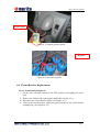
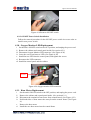
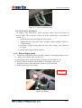
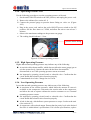
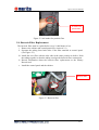
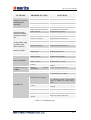
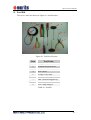
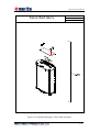
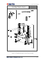
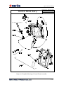
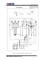
1
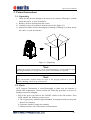
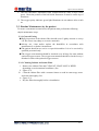
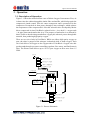
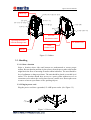
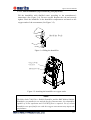
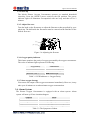
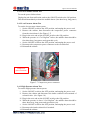
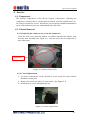
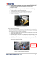
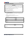
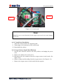
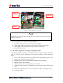
-
Q155 Service Manual
Table of Contents
1. Introduction
1-1
1.1. Intended Use............................................................................................... 1-1
1.2. How to Use Service Manual ....................................................................... 1-1
1.3. Safety Rules ............................................................................................... 1-2
1.3.1. Warning .............................................................................................. 1-2
1.3.2. Precaution........................................................................................... 1-2
1.4. Warranty..................................................................................................... 1-3
1.5. Specifications ............................................................................................. 1-4
2. Patient Instructions
2-1
2.1. Unpacking .................................................................................................. 2-1
2.2. Check ......................................................................................................... 2-1
2.3. Routine Maintenance by the patient ............................................................ 2-2
2.3.1. General Caring.................................................................................... 2-2
2.3.2. Cleaning Cabinet Air Intake Filter....................................................... 2-2
2.3.3. Humidifier .......................................................................................... 2-1
3. Operation
3-1
3.1. Description of Operation............................................................................. 3-1
3.2. Exterior Parts.............................................................................................. 3-2
3.3. Handling..................................................................................................... 3-3
3.3.1. Select a location.................................................................................. 3-3
3.3.2. Plug in power cord.............................................................................. 3-3
3.3.3. Connect humidifier (if prescribed by your physician) .......................... 3-4
3.3.4. Start up ............................................................................................... 3-5
3.3.5. Adjust flow rate .................................................................................. 3-5
3.3.6. Oxygen purity indicator ...................................................................... 3-5
3.3.7. Start oxygen therapy ........................................................................... 3-5
3.4. Alarm System............................................................................................. 3-5
3.4.1. Power Failure Alarm Test.................................................................... 3-6
3.4.2. Low Pressure Alarm Test .................................................................... 3-6
3.4.3. High Pressure Alarm Test.................................................................... 3-6
3.4.4. Overheating Alarm Test ...................................................................... 3-7
4. Service
4-1
4.1. Components................................................................................................ 4-1
4.2. Cabinet Removal ........................................................................................ 4-1
4.2.1. Removing the cabinet to access the air compressor ............................. 4-1
4.2.2. Caster Replacement ............................................................................ 4-1
4.3. Unit Block Replacement ............................................................................. 4-2
-i-
Q155 Service Manual
4.3.1. Solenoid Valve Assembly Replacement ............................................... 4-2
4.3.2. Solenoid Coil Replacement ................................................................. 4-1
4.3.3. Sieve Bed Replacement....................................................................... 4-2
4.4. Compressor ................................................................................................ 4-3
4.4.1. Compressor Maintenance .................................................................... 4-3
4.4.2. Compressor Assembly Replacement.................................................... 4-3
4.4.3. Compressor Relief Valve Test and Replacement .................................. 4-4
4.4.4. Capacitor Replacement ....................................................................... 4-5
4.5. Axial Fan Replacement............................................................................... 4-6
4.6. Circuit Board Replacement ......................................................................... 4-7
4.6.1. Circuit Board Removal ....................................................................... 4-7
4.6.2. Circuit Board Installation .................................................................... 4-8
4.6.3. Oxygen Sensor Circuit Board Removal............................................... 4-8
4.6.4. Oxygen Sensor Circuit Board Installation ........................................... 4-9
4.7. Product Regulator Setting and Replacement................................................ 4-9
4.8. Circuit Breaker Replacement .....................................................................4-10
4.8.1. Circuit Breaker Removal....................................................................4-10
4.8.2. Circuit Breaker Installation ................................................................4-11
4.9. ON/OFF Power Switch Replacement .........................................................4-11
4.9.1. ON/OFF Power Switch Removal .......................................................4-11
4.9.2. ON/OFF Power Switch Installation....................................................4-12
4.10.
Oxygen Monitor LED Replacement ...................................................4-12
4.11.Hour Meter Replacement ...........................................................................4-12
4.12.
Flow meter Replacement....................................................................4-13
4.12.1. Flow meter Removal..........................................................................4-13
4.12.2. Flow meter Installation ......................................................................4-14
4.13.
Buzzer Replacement ..........................................................................4-14
4.14.
Operating Pressure Test......................................................................4-15
4.15.
High Operating Pressure ....................................................................4-15
4.16.
Low Operating Pressure .....................................................................4-15
4.17.
Leak Test Procedure...........................................................................4-16
5. Maintenance
5.1.
5.2.
5.3.
5.4.
5-1
Routine Maintenance .................................................................................. 5-1
Cabinet Air Inlet Filter ................................................................................ 5-1
Air Intake Fine Particle Filter...................................................................... 5-1
Bacteria Filter Replacement ........................................................................ 5-2
6. Troubleshooting
6-1
7. Spare Parts
7-1
8. Tool Kit
8-1
Appendix A: Exploded Drawings ......................................................................A-1
ii
Q155 Service Manual
List of Illustrations
Figure 2-1 Unpacking............................................................................................. 2-1
Figure 2-2 Position of Cabinet Filter ...................................................................... 2-3
Figure 2-3 Clean Cabinet Filter .............................................................................. 2-1
Figure 3-1 Process Schematic................................................................................. 3-1
Figure 3-2 Cabinet ................................................................................................. 3-3
Figure 3-3 Power Cord........................................................................................... 3-3
Figure 3-4 Filling the humidifier ............................................................................ 3-4
Figure 3-5 Attaching the humidifier to oxygen outlet.............................................. 3-4
Figure 3-6 Adjusting the flowrate ........................................................................... 3-5
Figure 3-7 Compressor power connector ................................................................ 3-6
Figure 3-8 Intake solenoid coil and terminal........................................................... 3-7
Figure 3-9 Temperature sensor ............................................................................... 3-7
Figure 4-1 Cabinet fixed screws ............................................................................. 4-1
Figure 4-2 Caster replacement ................................................................................ 4-1
Figure 4-3 waste outlet/air inlet/oxygen outlet ........................................................ 4-2
Figure 4-4 Remove solenoid valve ......................................................................... 4-1
Figure 4-5 Remove solenoid coil ............................................................................ 4-1
Figure 4-6 the mounting band of sieve bed ............................................................. 4-2
Figure 4-7 The suction and feed tubes of compressor ............................................. 4-4
Figure 4-8 The power lead of compressor............................................................... 4-4
Figure 4-9 Loose relief valve.................................................................................. 4-5
Figure 4-10 The capacitor of compressor................................................................ 4-5
Figure 4-11 Intake axial fan.................................................................................... 4-6
Figure 4-12 Exhaust axial fan................................................................................. 4-6
Figure 4-13 Circuit board ....................................................................................... 4-8
Figure 4-14 Oxygen sensor board........................................................................... 4-9
Figure 4-15 Output pressure detect ........................................................................4-10
Figure 4-16 Pressure regulator...............................................................................4-10
Figure 4-17 Leads of Circuit breaker and ON/OFF switch.....................................4-11
Figure 4-18 Unscrew circuit breaker......................................................................4-11
Figure 4-19 Remove ON/OFF switch ....................................................................4-12
Figure 4-20 Oxygen monitor LED connector.........................................................4-12
Figure 4-21 Press down tabs of hour meter............................................................4-13
Figure 4-22 Remove hour meter ............................................................................4-13
Figure 4-23 Uscrew flowmeter nuts.......................................................................4-14
Figure 4-24 Buzzer................................................................................................4-14
Figure 4-25 Detect operating pressure ...................................................................4-15
Figure 5-1 Cabinet air inlet filter ............................................................................ 5-1
Figure 5-2 Air intake fine particle filter .................................................................. 5-2
Figure 5-3 Bacteria filter ........................................................................................ 5-2
Figure 8-1 Tool Kit of Service ................................................................................ 8-1
- iii -
Q155 Service Manual
Figure A-1 Exploded Drawing of Base Assembly...................................................A-2
Figure A-2 Exploded Drawings of Housing Assembly............................................A-3
Figure A-3 Exploded Drawing of Sieve Bed & Valve Assembly .............................A-4
Figure A-4 Exploded Drawings of Solenoid Valve Assembly..................................A-5
Figure A-5 Exploded Drawing of Sieve Bed Assembly...........................................A-6
Figure A-6 Exploded Drawing of Central Frame Assembly ....................................A-7
Figure A-7 Exploded Drawing of Muffler Assembly...............................................A-8
Figure A-8 Exploded Drawing of Air Compressor Assembly..................................A-9
Figure A-9 Exploded Drawing of Central Frame Assembly ..................................A-10
Figure A-10 Exploded Drawing of Harness Assembly .......................................... A-11
Figure A-11 Exploded Drawing of Accessories.....................................................A-12
iv
Q155 Service Manual
List of Tables
Table 1-1 List of specified warranty period components ......................................... 1-3
Table 1-2 List of consumable.................................................................................. 1-3
Table 1-3 Specification of Oxygen Concentrator .................................................... 1-4
Table 3-1 LED Indicator vs. Oxygen Purity............................................................ 3-5
Table 3-2 The Symptom of Alarm .......................................................................... 3-5
Table 6-1 Troubleshooting...................................................................................... 6-2
Table 7-1 Spare Parts.............................................................................................. 7-1
Table 8-1 Tool Kit .................................................................................................. 8-1
- ii -
Q155 Service Manual
1. Introduction
The Merits oxygen concentrators are as a solution to deliver a clean, portable and
continuous oxygen supply for homecare usage. Merits introduces proudly the Q155
Oxygen Concentrator. These concentrators were built with quality workmanship and
designed to be highly reliable systems while maintaining cost effective operation.
Since Merits is ISO 13485 and FDA QSR system approved, we have pledged to build
only products designed for unmatched reliability and endurance. Subsequently, we
are confident that our systems will deliver the necessary consistent concentrated
oxygen and flow rate as ordered by your attending physician. Smart monitoring and
security control systems allow for constant awareness of possible failures and or
malfunctions. The advanced technology utilized by Merits ensures that the patient
will always be alerted with audio and visual alarm systems.
1.1. Intended Use
The Merits Oxygen Concentrator is intended to be used to supply supplemental
oxygen to patients in their home. The devices are not intended for life support nor
do they provide any patient monitoring capabilities.
Caution
Federal Law restricts this device to sale by or on the order of a physician.
Caution
Do not adjust your prescribed level of oxygen flow without consulting your
physician.
1.2. How to Use Service Manual
This manual provides instruction for service engineer only to service the Merits
Q155 Oxygen Concentrator. This manual includes whole sections in the following:
n Introduction
n Patient Instructions
n Operation
n Service
n Maintenance
n Troubleshooting
All section titles, subject subtitles and illustration are listed in the Table of Contents.
Note
This manual specifically instruction for service engineers and distributors
only. This is not a manual for patient use.
- 1-1 -
Q155 Service Manual
1.3. Safety Rules
As you read the manual, please pay attention to all of following:
1.3.1. Warning
n Fire Hazard-Oxygen promotes rapid burning. No Smoking or Open Flames.
n Electrical Shock Hazard - do not remove the cabinet or open the cover.
n Disconnect the power cord from the electrical outlet before cleaning or
servicing.
n Do not place this equipment near hot, sparking or burning objects.
n Do not use oil or grease on or near this device.
n Do not use the concentrator in the presence of pollutants or dangerous fumes.
n An alternate source of oxygen should always be available to avoid any
interruption in supply.
n This unit is not intended for life sustaining or life supporting applications.
n Turn the unit off when it is not in use.
n In the event of an alarm, contact your equipment provider.
n If you experience any signs of discomfort, contact your physician
immediately.
n Merits recommends that each concentrator be on and running for a minimum
of 60 minutes at a time.
n Keep the cord away from HEATED or HOT surfaces.
n NEVER drop or insert any object into any opening.
n NEVER block the air openings of the product or place it on a soft surface, such
as a bed or couch, where the air opening may be blocked.
n Avoid the operation in wet or damp locations.
n Geriatric, pediatric, or any other patients unable to communicate discomfort
while using this concentrator may need additional monitoring under
physicians or medical professionals.
n Children may need pediatric flowmeter to use with this concentrator, consult
your physician before usage.
1.3.2. Precaution
n Always plug in a 15 AMP, grounded circuit. DO NOT USE AN EXTENSION
CORD.
n Place the unit where sides and bottom are unobstructed to ensure proper
airflow. (Be sure that the machine is placed away from drapes or other objects
that might block the flow of incoming air and/or alarm indicators.)
n Only operate the concentrator in an upright position.
n Do not use oxygen tubing that exceeds 50 feet in length. The manufacturer
recommends crush resistant tubing.
n Do not place liquids on the unit or use liquids to clean the unit. Do not use
petroleum-based solvents. Clean unit and power cord with mild household
1-2
Q155 Service Manual
cleaner applied with a damp cloth or sponge, then wipe dry.
n The Salter Labs 7100 350c.c. Bubble Humidifier and the B&F Medical Bubble
Humidifier are suitable for use with the Oxygen Concentrators. Or a
humidifier capable of 30 psi operation and 15 LPM of flow is required. Use of
certain humidifiers not specified for use with this oxygen concentrator may
impair the performance.
n Always choose the FDA or CE approved accessories, such as Masks or
cannulas & Humidifiers to ensure the reliability and performance.
n Different personnel to prevent cross infection should never use the same mask
or cannula.
1.4. Warranty
Merits Health Products Co., Ltd. warrants the Oxygen Concentrator to be free from
detect in general parts for a period of 5 years from the date of purchase excluding
the parts which warranty are specified on Table 1-1. Please tell your customer for
more details. This warranty is limited to the original purchaser of the Oxygen
Concentrator. Any defective part or assembly will be repaired or replaced, at the
sole discretion and determination of Merits Health Products Co., Ltd., if the unit has
been properly operated during the warranty period. Normal maintenance items and
disposable components (see Table 1-2) are not covered by this warranty. Shipping
charges, if any, shall be paid by the purchaser.
Note: There is no other express warranty. Implied warranties, including those of
merchantability and fitness for a particular purpose, are limited to the
duration of the express limited warranty and to the extent permitted by law
and all implied warranties are excluded. This warranty does not cover
providing a loaner Oxygen Concentrator, compensating for costs incurred for
Oxygen Concentrator rental, or labor costs incurred in repairing or replacing
defective part(s).
Component
Compressor
Part Number
4-S01
Molecular Sieve
2-S22
Warranty Period
10,000 hour
Note
1 year
Table 1-1 List of specified warranty period components
Component
Intake Foam
Part
Number
1-P19
Note
Clean every week
Bacteria Filter
1-P43
Replace after every 10,000hr use
Intake Filter
3-P41
Replace on clean condition
Table 1-2 List of consumable
1-3
Q155 Service Manual
1.5. Specifications
Electrical Requirements
115VAC±10﹪, 60Hz / 230VAC±10﹪, 50Hz
Rated Current Input
3.5A (115VAC/60Hz); 1.8A (230VAC/50Hz)
Sound Level
48dB(A) Average
Operating Altitude
Do not use at altitude over 4000 meters.
Oxygen Concentration
≧90﹪at 1~5LPM
* Stated performance maximum achieved after 60 min.
of run time.
6±0.5psi. (40±4 kPa.)
Oxygen Delivery Pressure:
Optional Oxygen Sensor
Oxygen Purity
LED Indicator
Over 85﹪(±3﹪)
GREEN Indicator light
70﹪(±3﹪) to 85﹪(±3﹪)
YELLOW Indicator light
Below 70﹪(±3﹪)
RED Indicator light
Flow
Range
/
Maximum
Recommended Flow
Average Power Consumption
0-5 LPM / 5 LPM
Pressure Relief Activation
250kPa±10﹪
Filters
Cabinet, Bacteria and Compressor Inlet
Alarms – (Visual/Audible)
High temperature w/ compressor – power shutdown
High / Low pressure alarm
Power loss alarm
68cm(26.8”) High × 45cm(17.7”) Wide × 33cm(13”) Deep
(115VAC/60Hz)Circuit
(230VAC/50Hz)Circuit
Breaker: 8A
Breaker: 4A
Dimensions
Circuit Breaker & Fuse
Weight
Shipping Weight
Operating Ambient Temperature
Cabinet
Regulatory Listing
Change in Max. Flow with 7 kpa
Back Pressure
Recommended Storage and
Shipping Temperature
350W
24Kg (53lb)
27Kg (59.5lb)
10℃ ~ 35℃
Impact Resistant flame-retardant plastic cabinet
CSA 601 / UL 2601/ IEC/EN-60601-1
0.3 LPM
Dry (Up to 95﹪ non-condensing), well ventilated area -20
℃ ~ 60℃
Table 1-3 Specification of Oxygen Concentrator
(1). Conditions may vary based on altitude above sea level, barometric pressure and temperature.
Specification subjects to change without notice.
(2). This product complies with the following standards: C22.2 No 601.1-M90, UL Std. No 2601-1 and
IEC/EN 60601-1.
(3). For electromagnetic compatibility the standards are based as follow: CSA 601.1-2 and IEC/EN
60601-1-2.
(4). Protection against electric shock is classified as Type II.
(5). Degree of protection against electric shock is classified as Type BF.
(6). Mode of operation belongs to continuous mode.
(7). Equipment not suitable for use in the presence of a flammable anesthetic mixture with air or with
oxygen or nitrous oxide
(8). Degree of protection against ingress of water is rated as IPX0.
1-4
Q155 Service Manual
2. Patient Instructions
2.1. Unpacking
i.
Check for any obvious damage to the carton or its contents. If damage is evident,
notify the carrier, or your local dealer.
ii. Remove all loose packing from the carton.
iii. Carefully remove concentrator from the carton.(See Figure 2-1)
iv. Inspect the cabinet exterior thoroughly for damage. If damage is evident, notify
the carrier, or your local dealer.
Norm
al
Oxyg
en
Abnor
Puri
mal
85%
ty
Aut
o- Shu
t-
Down
!
!
Figure 2-1 Unpacking
Note
Unless the oxygen concentrator is to be used immediately, retain container and
packing materials for storage until use of the concentrator is required.
Note
The concentrator should always be kept in the upright position to prevent
cabinet damage while being transported.
2.2. Check
Q155 Oxygen Concentrator is tested thoroughly to make sure the function is
normal after manufacture. Please perform the following procedure to ensure no
damage occurred in shipping.
i. Plug in the power cord and set the ON/OFF switch to the ON position. Then
check whether the following occurs or not:
a. The oxygen purity indicator lights illuminate accompanied with one beep and
then off in 2 minutes.
b. Listen the sound of compressor running.
c. Exhaust air flows out of the bottom of concentrator.
- 2-1 -
Q155 Service Manual
ii. Turn the flowmeter adjustment knob counterclockwise until it stops (wide
open). Check the position of the ball inside flowmeter. It must be on the top of
flowmeter.
iii. The oxygen purity indicator green light illuminates in ten minutes after switch
on.
2.3. Routine Maintenance by the patient
To ensure concentrator normal work, the patient must perform the following
simple maintenance steps.
2.3.1. General Caring
n Daily inspection of the cabinet filter should occur. Lightly vacuum or sweep
off. Do not use any sharp or corrosive materials.
n Always use, clean and/or replace the humidifier in accordance with
manufacturer's or dealer's instructions.
n The patient should never service or open this machine. It is to be serviced by
qualified personnel only.
n The oxygen concentration should be checked every 90 days for units without
optional oxygen sensors. The oxygen concentration should be checked every 6
months for units with optional oxygen sensors.
2.3.2. Cleaning Cabinet Air Intake Filter
i. Remove the cabinet filter and CLEAN AT LEAST ONCE A WEEK
depending on environmental conditions. (See
ii. Figure 2-2)
iii. Clean the cabinet filter with a vacuum cleaner or wash in warm soapy water
and rinse thoroughly. (See
iv. Figure 2-3)
v. Dry the filters thoroughly before reinstallation.
2-2
Q155 Service Manual
Intake Filter
Cabinet Filter
Figure 2-2 Position of Cabinet Filter
2-3
Q155 Service Manual
Figure 2-3 Clean Cabinet Filter
2.3.3. Humidifier
Note
To clean the oxygen humidifier, follow the instructions provided by the
manufacturer. If none are provided, follow these steps
i. Clean the humidifier every day.
ii. Wash it in soapy water and rinse it with a solution of 10 parts water and 1 part
vinegar.
iii. Rinse again with hot water and refill with distilled water to the level shown
on the humidifier.
- 2-1 -
Q155 Service Manual
3. Operation
3.1. Description of Operation
Figure 3-1 shows the normal airflow route of Merits Oxygen Concentrator. First, air
is drawn into the cabinet through the intake filter and muffler, which helps quiet the
compressor's intake sound. Then Air enters compressor and is pressurized in the
compressor. Pressurized air then passes through a heat exchanger, which reduces
the temperature of the compressed air. Next the solenoid valve developed by Merits
direct compressed air into Unit Block (solenoid valve + sieve bed×2 + oxygen tank
+ air pipe) that contain molecular sieve. The property of molecular sieve material is
that it is able to adsorb nitrogen and allow oxygen pass when air passes through this
material, thus producing high purity oxygen.
There are two sieve beds in Unit Block. While one allows high purity oxygen to
pass, the other is purged of the nitrogen it adsorbed while it made oxygen. Each
sieve bed delivers its oxygen to the oxygen tank of Unit Block. Oxygen exits this
product tank through a pressure-controlling regulator, flow meter, and final bacteria
filter. The Pioneer unit delivers up to 93±3% pure oxygen at flow rates from 1-5
LPM.
AIR IN
F
INTAKE FILTER
M/L
INTAKE MUFFLER
M
AIR-COMPRESSOR
HEAT EXCHANGER
MUFFLER
SOLENOID
VALVE
ELECTRONICAL
CONTROL
CIRCUIT (NEW)
SIEVE BED x2
OXYGEN TANK
UNIT
BLOCK
ALL IN ONE
OXYGEN OUT
R
REGULATOR
F
BACTERIA FILTER
FLOW METER
Figure 3-1 Process Schematic
- 3-1 -
Q155 Service Manual
3.2. Exterior Parts
Exterior parts described below:
n Exterior Cabinet
The Exterior Cabinet which material is ABS is strength durability. It is made
up of front and rear cabinet.
n Flowmeter/Knob
Displays and controls the oxygen flow rate.
n ON/OFF Power Switch
Starts and stops the operation of concentrator.
n Circuit Breaker
Cut off concentrator after an electrical overload.
n Oxygen Outlet
The connection port for humidifier.
n Operating Instruction Label
The operating instruction for easy reference by the patient.
n Warning Label
Indicates that you must reference important information.
n Serial Number Label
Shows the serial number of the concentrator.
n Cabinet Air Intake Filter
Cleans the Air enters the concentrator.
n Electrical Specification Label
Indicates power requirements and safety approvals.
n Air Exhaust Vents
Exhaust Air exits the concentrator.
n Hand Grips
Convenience to move the concentrator.
n Power Cord Socket
Plug in power cord.
n Casters
On the bottom, provide convenience to move the concentrator.
3-2
Q155 Service Manual
Hand Grip
Oxygen Purity Indicator Lights
Flowmeter
Flow Adjustment Knob
Norm
Ox
al
yg
Abnor
m
en
al
85%
Pu
ri ty
Aut
o-Shut
- Down
Power Switch
Circuit Breaker
Cabinet Filter
!
Oxygen Outlet
!
Power Cord
Cabinet Filter Holder
Electrical
Specification Label
Operating Instruction
Label & Warning Label
Air Exhaust Vent
Serial
Number Label
Caste r
Figure 3-2 Cabinet
3.3. Handling
3.3.1. Select a location
Select a location where sides and bottom are unobstructed to ensure proper
airflow. Be sure that the machine is placed away from drapes or other objects that
might block the flow of incoming air and/or alarm indicators. The area should be
free of pollutants or dangerous fumes. The unit should be placed on a stable level
surface. The location should have access to a power outlet without use of an
extension cord or where the cord is placed across a traffic area. Do not place near
a source or heat or open flame or hot, sparking objects.
3.3.2. Plug in power cord
Plug the power cord into a grounded, 15 AMP power outlet. (See Figure 3-3)
Power
Outlet
Figure 3-3 Power Cord
3-3
Q155 Service Manual
3.3.3. Connect humidifier (if prescribed by your physician)
Fill the humidifier with distilled water according to the manufacturer’s
instructions (See Figure 3-4). Do not overfill. Replace the cab and securely
tighten. Place the humidifier in the humidifier compartment and attach to the
oxygen outlet of the concentrator (See Figure 3-5).
Humidifier Bottle
Figure 3-4 Filling the humidifier
Oxygen Outlet
Connector
Norm
al
Oxyge
n Pu
A bno
rma
l 85
%
rity
A uto
-Sh
ut-D
own
Humidifier Outlet
Figure 3-5 Attaching the humidifier to oxygen outlet
Note
The Salter Labs 7100 350c.c. Bubble Humidifier and the B&F Medical Bubble
Humidifier are suitable for use with the Oxygen Concentrators. Or a humidifier
capable of 30 Psi operation and 15 LPM of flow is required. Use of certain
humidifiers not specified for use with this oxygen concentrator may impair the
performance.
3-4
Q155 Service Manual
3.3.4. Start up
The Merits Pioneer Oxygen Concentrator operates on standard household
electricity. Press the ON/OFF power switch to the ON position. The power
indicator light will illuminate accompanied with one beep and then off in 2
minutes.
3.3.5. Adjust flow rate
Turn the knob on the flowmeter to adjust the flowrate to that prescribed by your
physician. The ball inside the flowmeter must be centered on the flowline for the
desired flow rate.
5
4
3
2
Ball
1
O2
5
4
3
2
1
Norm
al
Oxy
A bn
ge
orm
al 8
n Pu
5%
rit y
A uto-S
hu
t-Do
wn
Flow Knob
Figure 3-6 Adjusting the flowrate
3.3.6. Oxygen purity indicator
This feature monitors the purity of oxygen generated by the oxygen concentrator.
The color of indicator light represent as following:
Oxygen Purity
LED Indicator
Over 85﹪(±3﹪)
GREEN Indicator light
70﹪(±3﹪) to 85﹪(±3﹪)
YELLOW Indicator light
Below 70﹪(±3﹪)
RED Indicator light
Table 3-1 LED Indicator vs. Oxygen Purity
3.3.7. Start oxygen therapy
You can use the output of the oxygen concentrator immediately. However, it may
take up to 60 minutes to reach maximum oxygen concentration.
3.4. Alarm System
The Pioneer Oxygen Concentrator is equipped with an alarm system. Alarm
system will start up if four situations happen:
Symptom
Alarm
Power Loss ALARM
Overheating ALARM
High Pressure ALARM
Low Pressure ALARM
One short beep, long pause
Two short beep, long pause-power shutdown
Three short beep, long pause (>2.2±0.2kgf/cm2)
Four short beep, long pause (<0.7±0.2kgf/cm2)
Table 3-2 The Symptom of Alarm
3-5
Q155 Service Manual
3.4.1. Power Failure Alarm Test
To test the power failure alarm:
Unplug the unit from wall outlet, and set the ON/OFF switch to the ON position.
This should immediately activate the audible alarm. (One short beep, long pause)
3.4.2. Low Pressure Alarm Test
To test the low-pressure alarm system:
i. Set the ON/OFF switch to the OFF position, and unplug the power cord.
ii. Remove the cabinet, then disconnect the compressor power connector
from the circuit board. (See Figure 3-7)
iii. Plug in the unit, and set the ON/OFF switch to the ON position.
iv. When the pressure is 0.7±0.2kgf/cm2 below, the audible alarm should be
four short beep, long pause and repeat this cycle.
v. Set the ON/OFF switch to the OFF position, and unplug the power cord.
vi. Reconnect the compressor power connector to the circuit board.
vii. Reinstall the cabinet.
Compressor
power connector
Figure 3-7 Compressor power connector
3.4.3. High Pressure Alarm Test
To test the High-pressure alarm system:
i. Set the ON/OFF switch to the OFF position, and unplug the power cord.
ii. Remove the cabinet and disconnect the intake solenoid coil terminals of
solenoid valve. (See Figure 3-8)
iii. Plug in the unit, and set the ON/OFF switch to the ON position.
iv. When the pressure is above 2.2±0.2kgf/cm2, the audible alarm should be
three short beep, long pause and repeat this cycle.
v. Set the ON/OFF switch to the OFF position, and unplug the power cord.
vi. Reconnect the intake solenoid coil terminal.
vii. Reinstall the cabinet.
3-6
Q155 Service Manual
Figure 3-8 Intake solenoid coil and terminal
3.4.4. Overheating Alarm Test
To test the overheating alarm:
i. Set the ON/OFF switch to the OFF position, and unplug the power cord.
ii. Remove the cabinet.
iii. Plug in the unit, and set the ON/OFF switch to the ON position.
iv. Use dryer to heat the temperature sensor. (See Figure 3-9)
v. When temperature is higher than 600C, alarm system will start the audible
alarm up.
vi. Reinstall the cabinet.
Temperature
sensor
Figure 3-9 Temperature sensor
3-7
Q155 Service Manual
4. Service
4.1. Components
The internal composition of the Merits Oxygen Concentrator, including the
compressor, solenoid valves, circuit board, unit block, axial fan, and all filters etc.,
are easily accessible for service. This allows you to perform scheduled maintenance,
repair, and replacement of parts with minimal time and effort.
4.2. Cabinet Removal
4.2.1. Removing the cabinet to access the air compressor
Loose the four screws from the bottom of cabinet, and take the cabinet apart
from the base assembly (See Figure 4-1). You can access the air compressor or
most other parts.
Fixed screw
Figure 4-1 Cabinet fixed screws
4.2.2. Caster Replacement
i.
Lay down concentrator on the ground to access easily the caster wheels
mounted on base plate.
ii. Remove the caster nut with a 12.5mm socket. (See Figure 4-2)
iii. Install the new caster and tighten the nut.
Figure 4-2 Caster replacement
- 4-1 -
Q155 Service Manual
4.3. Unit Block Replacement
4.3.1. Solenoid Valve Assembly Replacement
The oxygen concentrator uses solenoid valves to control airflow. It is not
necessary to do scheduled maintenance for the solenoid valves. If the valve has
got some trouble, you can easily replace the valve. The steps of replacing
solenoid valve are as following:
i.
Set the ON/OFF switch to the OFF position, and unplug the power cord.
ii. Remove the cabinet. (See section 4.2.1)
iii. Disconnect the terminal of the solenoid coil. (See Figure 3-8)
iv. Remove the clamps and disconnect the tubes on the waste outlet/air
inlet/oxygen outlet, disconnect the PU tube from the pressure detect
fitting. (See Figure 4-3)
v. Loose the six screws of solenoid valve and remove solenoid valve. (See
Figure 4-4)
vi. Install new solenoid valve assembly and tighten six screws.
vii. Reconnect the tubes and clamps of the waste outlet/air inlet/oxygen
outlet. Connect the PU tube to pressure inspect fitting located at valve
base.
viii. Reconnect the terminal of solenoid valve.
Oxygen outlet
Air inlet
Pressure detect
fitting
Waste air outlet
Figure 4-3 waste outlet/air inlet/oxygen outlet
4-2
Q155 Service Manual
Six screws of the
solenoid valve
Figure 4-4 Remove solenoid valve
4.3.2. Solenoid Coil Replacement
i.
ii.
iii.
iv.
Set the ON/OFF switch to the OFF position, and unplug the power cord.
Remove the cabinet. (See section 4.2.1)
Disconnect the terminal of the damaged solenoid coils. (See Figure 3-8)
Loose the fixing nuts above solenoid coils and remove the coils.(See Figure
4-5)
v. Install new Coils.
vi. Tighten the coils’ fixing nuts and connect the terminals of coils.
Fixing nuts
Figure 4-5 Remove solenoid coil
- 4-1 -
Q155 Service Manual
4.3.3. Sieve Bed Replacement
After long term usage, the ability of producing oxygen of molecular sieve
finally decline. It is necessary to replace sieve bed for solving this issue. Please
pay attention to replace both sieve bed at the same time. Please follow the
following procedure to replace sieve bed:
Caution
Do not expose molecular sieve (contents of sieve bed) to air for an extended
period of time. Prolonged exposure of molecular sieve to the moisture in room
air results in contamination and permanent damage to the sieve material. Keep
all openings to the sieve beds sealed.
i.
ii.
iii.
iv.
v.
vi.
Set the unit's ON/OFF switch to the OFF position, and unplug the power
cord.
Remove the cabinet.(See section 4.2.1)
Loose the mounting band of sieve bed to free sieve beds. (See Figure 4-6)
Remove the sieve beds.
Remove solenoid valve assembly. (See Section 4.3.1)
Seal the openings on the top of the sieve beds to prevent moisture damage.
The mounting band
Figure 4-6 the mounting band of sieve bed
vii. To install the sieve bed, follow the sieve bed removal procedure in reverse
orders. It is important to secure clamps on all tubes to eliminate leaks.
viii. To check for leaks:
n Plug in the unit.
n Set the unit's ON/OFF switch to ON for three minutes with the flow meter
setting at the 5 LPM.
n Apply soapy water around the sieve beds tubing connections, and check
for leaks.
n Set the unit's ON/OFF switch to OFF, and unplug the power cord.
4-2
Q155 Service Manual
Note
Leaks can be so small in air loss that purity is not affected immediately. The
sieve material can become contaminated gradually. Careful leak testing is
important. (Refer to Section 2.16)
4.4. Compressor
The compressor produce compressed air to enter the sieve bed. The nitrogen is
adsorbed in the sieve bed and the oxygen to flow out of the sieve bed. The noise and
thermal energy of the concentrator result mainly from the compressor. So the
efficiency of producing oxygen and noise level of the concentrator are decided by
compressor. So there are two different conditions of the compressor that cause
concern: compressor output and noise level.
n Output
Compressor output refers to how much volume and pressure of compressed air
the compressor can produce. Because seals wear, the compressor output
reduces gradually after a long time period and results in the reduction of
oxygen purity. You can detect the oxygen purity at 5 lpm. If the purity is below
90%, the concentrator needs service.
n Noise Level
The conditions of the compressors bearings mainly determine its sound level. If
the bearings wear that they become too noisy, the compressor will need to be
rebuilt or replaced.
4.4.1. Compressor Maintenance
Preventative maintenance on the Merits compressor is not required. You do not
need to perform any maintenance on the compressor as long as the concentrator
output is within Merits’ specifications. (See Section 1.1)
4.4.2. Compressor Assembly Replacement
n Compressor Assembly Removal
To remove the compressor assembly for replacement, follow the below steps:
i. Set the unit's ON/OFF switch to the OFF position, and unplug the power
cord.
ii. Remove the cabinet and remove the crashproof plate above compressor.
(See section 4.2.1)
iii. Disconnect the feed and suction tubes, as shown in Figure 4-7
iv. Disconnect the two leads of compressor. (See Figure 4-8)
v. Take away compressor directly.
4-3
Q155 Service Manual
n Compressor Assembly Installation
To install the rebuilt compressor assembly:
i. Perform the compressor removal procedure in reverse order.
ii. Apply soapy water around the compressor tubing connections,
and check for leaking.
Suction tube
Feed tube
Crashproof Plate
Figure 4-7 The suction and feed tubes of compressor
Power lead of
compressor
Lead of
capacitor
Figure 4-8 The power lead of compressor
4.4.3. Compressor Relief Valve Test and Replacement
The procedure to test the compressor safety relief valve is as following:
i. Set the ON/OFF switch to the OFF position, and unplug the power cord.
ii. Remove the cabinet.
iii. Remove the cabinet and disconnect the intake solenoid coil terminals of
solenoid valves. (See Figure 3-8)
iv. Plug in the unit, and set the ON/OFF power switch to the ON position.
After approximately 10 seconds, the audible alarm will begin to sound
and when the pressure reaches 2.5±0.2kgf/cm2, the safety relief valve on
the compressor will make an air release sound. This means the valve is
working correctly.
4-4
Q155 Service Manual
v. Set the ON/OFF switch to the OFF position, and unplug the power cord.
vi. Reconnect the intake solenoid coil terminals of solenoid valve.
vii. Install the cabinet.
The procedure to replace the compressor safety relief valve is as following:
i.
ii.
iii.
iv.
Follow section 4.4.2 to remove compressor.
To loose the relief valve by using wrench. (See Figure 4-9)
To wind around type seal on the thread of new relief valve.
Install new relief valve.
Figure 4-9 Loose relief valve
4.4.4. Capacitor Replacement
The capacitor helps to start the compressor. If the compressor does not start when
the power is switched on, the capacitor may be defective and require replacement.
Please follow below steps to replace the capacitor:
i. Set the unit's ON/OFF switch to OFF position, and unplug the power cord.
ii. Remove the cabinet. (See 4.2.1)
iii. Disconnect the two lead wires to the capacitor (See Figure 4-8) and cut the
tie straps holding capacitor to another side of central frame. (See Figure
4-10)
iv. To install the new capacitor, connect the leads to new capacitor then fasten
the capacitor with new tie straps.
The capacitor
of compressor
Figure 4-10 The capacitor of compressor
4-5
Q155 Service Manual
4.5. Axial Fan Replacement
The intake axial fan for the unit is located aside of central frame and base assembly.
(See Figure 4-11) Refer to the troubleshooting chart in Section 4.0 of this manual
for instances where replacement of the fan may be required.
To replace the intake axial fan in central frame, take the following steps:
i. Set the unit's ON/OFF switch to the OFF position, and unplug the power cord.
ii. Remove the cabinet.(See section 4.2.1)
iii. Disconnect the fan wire connector (See Figure 4-11).
iv. Remove the screws and nuts on axial fan from central frame.(See Figure 4-11)
v. Install new intake axial fan to central frame and tighten the screws.
vi. Connect the fan wire connector.
vii. Reassemble the cabinet.
The fan wire
connector
The fan fixed
screws
Figure 4-11 Intake axial fan
To replace the exhaust axial fan in the base assembly, take the following steps:
i.
Set the unit's ON/OFF switch to the OFF position, and unplug the power
cord.
ii. Remove the cabinet.(See section 4.2.1)
iii. Disconnect the fan wire connector. (See Figure 4-11)
iv. Follow section 4.4.2 to remove compressor.
v. Disconnect the exhaust axial fan wire connector.
vi. Loose the four screws on exhaust axial fan to remove it. (See Figure 4-12)
The exhaust
fan wire
connector
Figure 4-12 Exhaust axial fan
4-6
Q155 Service Manual
4.6. Circuit Board Replacement
Caution
The Printed Circuit Boards (PCBs) contain components that are sensitive to
electrostatic discharge (ESD) and can damage the board if not handled
properly. As when handling any ESD-sensitive PCB, observe standard ESD
safety procedures. These procedures include the following:
n Handle the PCB by the edges only.
n Work on a grounded ESD mat.
n Wear a grounded wrist strap.
n Store PCBs only in anti-static bags.
4.6.1. Circuit Board Removal
i. Set the unit's ON/OFF switch to the OFF position, and unplug the power
cord.
ii. Remove the cabinet.(See section 4.2.1)
iii. Disconnect all connectors from the circuit board. (See
iv. Figure 4-13)
v. Remove the circuit board from supports. (See
vi. F
i
g
Handle
the new circuit board only by the edges to prevent electro static damage
to uthe unit.
r
Handle
the new circuit board only by the edges to prevent electro static damage
to ethe unit.
Note
Note
4-13)
Note
Handle the new circuit board only by the edges to prevent electro static damage
to the unit.
4-7
Q155 Service Manual
Support
Support
Figure 4-13 Circuit board
Note
Handle the new circuit board only by the edges to prevent electro static damage
to the unit.
4.6.2. Circuit Board Installation
i. Attach the circuit board to the supporting tabs.
ii. Firmly plug in all connectors to the circuit board.
iii. Reassemble the cabinet.
4.6.3. Oxygen Sensor Circuit Board Removal
i. Set the unit's ON/OFF switch to the OFF position, and unplug the power
cord.
ii. Remove the cabinet.(See section 4.2.1)
iii. Disconnect the wire connector from the oxygen sensor circuit board. (See
Figure 4-14)
iv. Remove clamps and the tubing from the oxygen sensor. (See Figure 4-14)
v. Remove the oxygen sensor circuit board from the supports.
4-8
Q155 Service Manual
Clamp and
Tubing
Connector
Support
Figure 4-14 Oxygen sensor board
Note
Handle the new oxygen sensor board only by the edges to prevent electro static
damage to the unit.
4.6.4. Oxygen Sensor Circuit Board Installation
i. Install the oxygen sensor circuit board on the supports.
ii. Firmly plug in the wire connector to the oxygen sensor circuit board.
iii. Firmly plug in the tubing to the oxygen sensor circuit board.
iv. Reconnect the cabinet.
4.7. Product Regulator Setting and Replacement
The product regulator enables you to set the pressure of oxygen output by the Merits
unit. To check for proper adjustment of the product regulator, take the following
steps:
i.
Set the unit's ON/OFF switch to the OFF position, and unplug the power cord
ii. Remove the cabinet.(See section 4.2.1)
iii. Plug the power cord, set the ON/OFF switch to the ON position
iv. Run the unit for three minutes.
v. Turn the flow meter adjustment knob set at 5 LPM.
vi. Connect pressure gauge (or manometer) at the oxygen outlet. (See Figure
4-15)
vii. Rotate the regulator knob on valve set to the 6.0±0.6psi. (See Figure 4-16)
viii. Install the cabinet.
4-9
Q155 Service Manual
Pressure gauge
Figure 4-15 Output pressure detect
Regulator
Figure 4-16 Pressure regulator
4.8. Circuit Breaker Replacement
4.8.1. Circuit Breaker Removal
i. Set the unit's ON/OFF switch to the OFF position, and unplug the power
cord.
ii. Remove the cabinet and control panel inside.(See section 4.2.1)
iii. Disconnect the circuit breaker leads. (See Figure 4-17)
iv. Unscrew the circuit breaker while you apply pressure to the circuit breaker
retaining ring. (See Figure 4-18)
4-10
Q155 Service Manual
Leads of
ON/OFF switch
Leads of circuit
breaker
Figure 4-17 Leads of Circuit breaker and ON/OFF switch
Figure 4-18 Unscrew circuit breaker
4.8.2. Circuit Breaker Installation
Follow the removal procedure for the circuit breaker in reverse order to install the
new circuit breaker.
4.9. ON/OFF Power Switch Replacement
4.9.1. ON/OFF Power Switch Removal
i. Set the unit's ON/OFF switch to OFF position, and unplug the power cord.
ii. Remove the cabinet and control panel inside.(See section 4.2.1)
iii. Disconnect the leads from the switch. (See Figure 4-17)
iv. Press in all four tabs in the back of the power switch, and remove the switch
through the control panel. (See Figure 4-19)
4-11
Q155 Service Manual
Figure 4-19 Remove ON/OFF switch
4.9.2. ON/OFF Power Switch Installation
Follow the removal procedure for the ON/OFF power switch in reverse order to
install a new power switch.
4.10. Oxygen Monitor LED Replacement
i. Set the unit's ON/OFF switch to the OFF position, and unplug the power cord.
ii. Remove the cabinet and control panel inside.(See section 4.2.1)
iii. Disconnect Oxygen Monitor LED connector. (See Figure 4-20)
iv. Loose the screws and remove LED. (See Figure 4-20)
v. Install the new LED into the control panel, and tighten the screws.
vi. Reconnect the LED connector.
vii. Install the control panel and the cabinet.
Screws
Figure 4-20 Oxygen monitor LED connector
4.11. Hour Meter Replacement
i.
ii.
iii.
iv.
v.
vi.
Set the unit's ON/OFF switch to the OFF position, and unplug the power cord.
Remove the cabinet and control panel inside. (See section 4.2.1)
Disconnect the terminal of hour meter from control board. (See Figure 4-21)
Push both sides of hour meter tabs away from the central frame. (See Figure
4-)
Remove the hour meter
Install the new hour meter into the central frame.
4-12
Q155 Service Manual
vii. Plug the hour meter terminal into control board.
viii. Install the control panel and the cabinet.
Figure 4-21 Press down tabs of hour meter
Figure 4-22 Remove hour meter
4.12. Flow meter Replacement
4.12.1. Flow meter Removal
i. Set the unit's ON/OFF switch to the OFF position, and unplug the power
cord.
ii. Remove the cabinet and the control panel inside.(See section 4.2.1)
iii. Cut the tie-wraps, and remove oxygen tubing from the flow meter fittings.
iv. Unscrew the flow meter nuts with a wrench. (See Figure 4-23)
v. Remove the flow meter through the control panel.
4-13
Q155 Service Manual
Figure 4-23 Uscrew flowmeter nuts
4.12.2. Flow meter Installation
To install a new flow meter, follow the flow meter removal procedure in
reverse order. Then perform a leak test on the connections as described in
section 4.17.
i. Install the flow meter through the control panel.
ii. Tighten the flow meter nuts with a wrench. (Torque setting at 62N-cm =
5.5inch-pound)
iii. Reconnect oxygen tubing from the flow meter fittings, and fasten the
tie-wraps.
iv. Install control panel and the cabinet.
4.13. Buzzer Replacement
i.
ii.
iii.
iv.
v.
vi.
Set the unit's ON/OFF switch to the OFF position, and unplug the power cord.
Remove the cabinet. (See section 4.2.1)
Disconnect buzzer connector from circuit board. (See Figure 4-24)
Remove buzzer from the central frame by loosing the two screws.
Install new buzzer and connect the connector to circuit board..
Install control panel and cabinet.
Connector
Figure 4-24 Buzzer
4-14
Q155 Service Manual
4.14. Operating Pressure Test
Use the following procedure to test the operating pressure of the unit.
i. Set the unit's ON/OFF switch to the OFF position, and unplug the power cord.
ii. Remove the cabinet.(See section 4.2.1)
iii. Connect the pressure gauge to pressure detect fitting on valve set. (Figure
4-25)
iv. Plug in the power cord, and set the unit's ON/OFF power switch to the ON
position. Set the flow meter to 5 LPM, and allow the unit to run at least 3
minutes.
v. Observe the maximum readings on the pressure test gauge.
vi. The reading should indicate 1~2 bar.
pressure detect fitting
Figure 4-25 Detect operating pressure
4.15. High Operating Pressure
Higher than normal operating pressure may indicate any of the following:
n A restrictive blow down muffler, which does not allow the waste (purge) gas to
exit the system freely. Operate the unit with the blow down muffler
disconnected to see if the operating pressure returns to normal.
n An improperly operating circuit board or solenoid valve. Confirm that the
circuit board and solenoid valves function properly.
n Contaminated sieve beds. Change the sieve beds.
4.16. Low Operating Pressure
Lower than normal operating pressure may indicate any of the following:
n A restriction in the suction resonator, which limits the amount of room air
available to the compressor. Disconnect the suction tube at the compressor,
and allow the unit to operate without the suction resonator to see if normal
operating pressure returns.
n An improperly operating circuit board or solenoid valve. Confirm that the
circuit board and solenoid valves function properly.
n A leak in the unit, which allows system pressure to escape. Leak test the unit.
(See section 4.17)
n A compressor with reduced output. Ensure that the purity level at the desired
liter flow is within Merits’ specifications. If it is below specifications, replace
- 4-15 -
Q155 Service Manual
or repair the compressor.
4.17. Leak Test Procedure
When you service the Pioneer unit, thoroughly leak test as outlined below. Use a
leak indicating solution or liquid soap and water, which create bubbles in the
presence of a leak.
A solution of one teaspoon of liquid soap per quart of water is sufficient.
i. Uncoil the power cord completely from its holder before use, and plug in the
unit.
ii. Set the unit's ON/OFF switch to the ON position, and turn on the flow meter
(set 5 LPM). Allow the unit to run for approximately three minutes.
iii. Remove the cabinet.(See section 4.2.1)
iv. In the compressor compartment, apply the solution to the heat exchanger
connections and fittings on the compressor.
v. On the back and front side, apply the solution to the Regulator, Solenoid Valve
fittings, Sieve Bed fittings, Flow Meter and Bacteria Filter.
Note
When you leak test, be sure to wipe off any excess water and protect all electrical
components from the solution.
4-16
Q155 Service Manual
5. Maintenance
5.1. Routine Maintenance
The Merits’ unit has two filters that require scheduled maintenance and
replacement. In addition, you must perform a test of purity concentration on the
unit at least every 90 days. Merits do not require preventative maintenance on the
compressor. You do not need to perform any compressor maintenance as long as
the merits’ unit remains within specifications at the desired flow rate.
5.2. Cabinet Air Inlet Filter
The cabinet air inlet filter is located at the cabinet aside. (See Figure 5-1) You can
easily remove it by hand.
Note
The filter may require daily cleaning if the Pioneer unit operates in a harsh
environment such as a house heated by wood, kerosene, or oil, or one with
excessive cooking or cigarette smoke.
Figure 5-1 Cabinet air inlet filter
5.3. Air Intake Fine Particle Filter
The particle filter replaced about every three months, if unit always run.
i. Set the unit's ON/OFF switch to the OFF position, and unplug the power cord.
ii. Remove the maintenance door.
iii. Remove old particle filter and install new one.
iv. Install maintenance door.
- 5-1 -
Q155 Service Manual
Air intake fine
particle filter
Figure 5-2 Air intake fine particle filter
5.4. Bacteria Filter Replacement
The bacteria filter must be replaced after every 10,000 hours of use.
i. Remove the cabinet and control panel.(See section 4.2.1)
ii. Separate the tubing from both sides of the filter attached at control panel.
(See Figure 5-3)
iii. Install the new filter with the inlet side in the same position as before. Push
the tubing together so that the tubing overlaps the bacteria filter connections.
iv. Record information about the bacteria filter replacement on the History
Record card.
v. Install the control panel and the cabinet.
Bacteria filter
Figure 5-3 Bacteria filter
5-2
Q155 Service Manual
6. Troubleshooting
SYMPTON
PROBABLE CAUSE
No power on wall outlet.
Power Loss while
power switch ON
Tripped or faulty circuit
breaker.
Faulty cable plug.
Faulty power switch
Faulty temperature sensor
Air outlet block
Over-Heating alarm
High Pressure alarm
SOLUTION
Inspect house circuit breakers or fuses.
Reset or replace the circuit breaker.
Replace the cable plug.
Replace the power switch.
Replace the temperature sensor
Keep oxygen concentrator at least
three-inch away from walls, draperies
or furniture.
Faulty Cooling fan
Replace the cooling fan.
Environmental temperature
too high
Control room temperature below 35℃
Faulty Solenoid Coil
Replace faulty Solenoid Coil
Faulty pressure sensor
Faulty Control Board
Clean foam filter or replace
Check the intake filter or replace it
Check all the tubes from the exhaust of
air compressor to the oxygen outlet or
Replace the related faulty tubes
Replace faulty pressure sensor
Replace Control Board
Faulty air compressor
Replace faulty air compressor
Restriction in air passages
Low Pressure alarm
Leaking
Leaking
Faulty oxygen monitor
board
Faulty regulator
Low Oxygen Purity
Faulty solenoid valve
Relief valve release
Faulty compressor flow
Sieve bed contaminated or
molecule sieve invalid
Environmental temperature
too high
Restriction in exhaust
muffler
Restriction in air passages
Refer section 4.17 Leak Test and repair
leaking.
Refer section 4.17 Leak Test and repair
leaking.
Replace faulty oxygen monitor board.
Replace faulty regulator or reset the
regulator
Replace faulty solenoid valve
Replace faulty relief valve
Replace or repair faulty compressor
Replace sieve bed
Control room temperature below 35℃
Replace or clean exhaust muffler
Clean foam filter or replace
Check the intake filter or replace it
Check all the tubes from the exhaust of
air compressor down to the oxygen
outlet or Replace the related faulty
tubes
- 6-1 -
Q155 Service Manual
SYMPTON
Compressor does not
run when power
switch ON
Compressor shut
down intermittently
when power switch
ON
Circuit breaker trips
repeatedly when
power switch ON
Buzzer not sound
Flow rate unstable
Cooling fan does not
working
PROBABLE CAUSE
SOLUTION
Power loss.
Faulty circuit board.
Faulty electrical connections
Faulty compressor.
Faulty capacitor.
Refer “Power loss solution”
Replace faulty circuit board.
Check electrical connections.
Replace faulty air compressor.
Replace faulty capacitor.
Faulty electrical connections
Check electrical connections.
Faulty capacitor
Replace faulty capacitor.
Faulty Cooling Fan
Replace faulty Cooling Fan
Faulty temperature sensor
Replace faulty temperature sensor
Faulty circuit board
Replace faulty circuit board
Faulty compressor
Replace faulty compressor
Faulty circuit breaker
Replace faulty circuit breaker
Faulty circuit board
Replace faulty circuit board
Faulty electrical connections
Check electrical connections
Faulty buzzer
Replace faulty buzzer
Faulty circuit board
Replace faulty circuit board
Faulty regulator
Replace faulty regulator.
Faulty solenoid valve
Replace faulty solenoid Valve
Faulty sieve bed
Replace faulty sieve bed
Leaking
Refer section 4.17 Leak Test and repair
leaking.
Defective
electrical
Connections
Defective Cooling fan
Check electrical connections
Replace faulty cooling fan
Clean foam filter or replace
Restriction in air passages
Low flow rate
Leaking
Check the intake filter or replace it
Check all the tubes from the exhaust of
air compressor down to the oxygen
outlet or Replace the related faulty
tubes
Refer section 4.17 Leak Test and repair
leaking.
Faulty or loosened regulator
Replace or reset the regulator
Faulty solenoid valve
Relief valve release on air
Compressor flow rate not
enough
Replace faulty solenoid valve
Replace relief valve
Repair or replace compressor
Table 6-1 Troubleshooting
6-2
Q155 Service Manual
7. Spare Parts
Spare parts which Merits offers are listed below. The part numbers of components
refer Appendix A: Exploded Drawings for details.
Part
Number
Component
Q’ty
Part
Number
Component
Q’ty
1-S01
Base Ass’y
1
1-P18
Maintenance Door
1
1-S02
Wind Mask Ass’y
1
1-P19
Intake Foam
1
1-S16
Cabinet Assy
1
1-P22
Knob
1
1-S17
Control Panel Ass’y
1
3-P01
Silicon Tubing
3
1-S18
Flow Meter Ass’y
1
3-P02
Silicon Tubing
3
1-S19
Flow Control Valve Ass’y
1
3-P03
PVC Tubing
3
2-S01
Solenoid Valve Ass’y
1
3-P04
PVC Tubing
3
2-S21
Unit Block Ass’y
1
3-P41
Intake Filter
1
2-S22
Sieve Bed Ass’y
1
3-P43
Bacteria Filter
1
3-S01
Central Frame Ass’y
1
9-P01
Circuit Board
1
3-S02
Crashproof Plate Ass’y
1
9-P02
Oxygen Monitor Board
1
3-S21
Intake Muffler Ass’y
1
9-P03
Panel Power Supply Wires Ass’y
1
3-S22
Outlet Muffler Ass’y
1
9-P04
Oxygen Monitor Board Wire
1
4-S01
Compressor Ass’y
1
9-P05
Hour Meter
1
9-S01
Buzzer Ass’y
1
9-P06
Valve Power Supply Wires
1
9-S02
Oxygen Monitor LED Ass’y
1
9-P07
FAN Power Supply Wire
1
9-P08
Breaker Wire
1
9-P09
ON/OFF Power Switch Wire
1
9-P10
Axial Fan
1
9-P11
Axial Fan
1
9-P12
Circuit Breaker
1
9-P13
ON/OFF Power Switch
1
9-P14
Power Cord
1
9-P15
Pressure Switch Wire
1
9-P31
User Manual
1
Table 7-1 Spare Parts
- 7-1 -
Q155 Service Manual
8. Tool Kit
The service tools are shown in Figure 8-1 and list below.
9
1
6
5
8
3
4
7
2
Figure 8-1 Tool Kit of Service
Item
Tool Name
1
Philips-head Screwdriver
2
Slotted-head Screwdriver
3
Needle-nose Pliers
4
Wire Cutters
5
Pressure Test Gauge
6
4mm T-head Hexagonal key
7
3mm T-head Hexagonal key
8
8mm Combination Wrench
9
Hose Clamp Stripper
Table 8-1 Tool Kit
- 8-1 -
Q155 Service Manual
Appendix A: Exploded Drawings
Base Assembly
Housing Assembly
Sieve Bed&Valve Assembly
Assembly of Solenoid Valve
Assembly of Sieve Bed
Central Frame Assembly
Muffler Assembly
Air Compressor Assembly
Control Panel Assembly
Harness Assembly
Accessories
- A-1 -
Q155 Service Manual
Base Ass'y
Drawing No: Q1A043-01(M)
Issue Date: 05/17/2007
Version:
0
Figure A-1 Exploded Drawing of Base Assembly
A-2
Q155 Service Manual
Housing Ass'y
Drawing No: Q1A044-01(M)
Issue Date: 05/17/2007
Version:
0
Figure A-2 Exploded Drawings of Housing Assembly
A-3
Q155 Service Manual
Sieve Bed & Valve Ass'y
Drawing No: Q1B043-01(M)
Issue Date: 05/17/2007
Version:
0
Figure A-3 Exploded Drawing of Sieve Bed & Valve Assembly
A-4
Q155 Service Manual
Solenoid Valve Ass'y
Drawing No: Q1B044-01(M)
Issue Date: 05/17/2007
Version:
0
Figure A-4 Exploded Drawings of Solenoid Valve Assembly
A-5
Q155 Service Manual
Sieve Bed Ass'y
Drawing No: Q1B045-01(M)
Issue Date: 05/17/2007
Version:
0
Figure A-5 Exploded Drawing of Sieve Bed Assembly
A-6
Q155 Service Manual
Central Frame Ass'y
Drawing No: Q1C052-01(M)
Issue Date: 05/17/2007
Version:
0
Figure A-6 Exploded Drawing of Central Frame Assembly
A-7
Q155 Service Manual
Muffler Ass'y
Drawing No: Q1C053-01(M)
Issue Date: 05/17/2007
Version:
0
Figure A-7 Exploded Drawing of Muffler Assembly
- A-8 -
Q155 Service Manual
Air Compressor Ass'y
Drawing No: Q1D042-01(M)
Issue Date: 05/17/2007
Version:
0
Figure A-8 Exploded Drawing of Air Compressor Assembly
A-9
Q155 Service Manual
Control Panel Ass'y
Drawing No: Q1E043-01(M)
Issue Date: 05/17/2007
Version:
0
TO OXYGEN SENSOR
Figure A-9 Exploded Drawing of Central Frame Assembly
A-10
Q155 Service Manual
Figure A-10 Exploded Drawing of Harness Assembly
- A-11 -
Q155 Service Manual
Accessory
Drawing No: Q1F044-01(M)
Issue Date: 05/17/2007
Version:
0
Figure A-11 Exploded Drawing of Accessories
- A-12 -