1
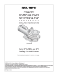
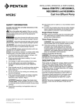
Series
For "C" Series Sleeved Impellers with positive locking screw
!
"
!
# !
"
"
"
$
PLEASE READ THE FOLLOWING INFORMATION PRIOR TO INSTALLING AND USING Webster PUMPS or
HAYWARD VALVES, STRAINERS, FILTERS, AND OTHER ASSOCIATED PRODUCTS. FAILURE TO FOLLOW
THESE INSTRUCTIONS MAY RESULT IN SERIOUS INJURY.
1.
2.
3.
4.
5.
6.
7.
8.
Webster and Hayward guarantees their products against defective material and workmanship only. Webster and Hayward
assume no responsibility for damage or injuries resulting from improper installation, misapplication, or abuse of any product.
Webster and Hayward assume no responsibility for damage or injury resulting from chemical incompatibility between their
products and the process fluids to which they are subjected. Compatibility charts provided in Webster and Hayward literature
are based on ambient temperatures of 70 ºF and are for reference only. Customer should always test to determine application
suitability.
Consult Webster and Hayward literature to determine operating pressure and temperature limitations before installing any
Webster and/or Hayward product. Note that the maximum recommended fluid velocity through any Webster and Hayward
product is eight feet per second. Higher flow rates can result in possible damage due to the water hammer effect. Also note
that maximum operating pressure is dependent upon material selection as well as operating temperature.
Webster and Hayward products are designed primarily for use with non-compressible liquids. They should NEVER be used or
tested with compressible fluids such as compressed air or nitrogen.
Systems should always be depressurized and drained prior to installing or maintaining Webster and Hayward products.
Temperature effect on piping systems should always be considered when the systems are initially designed. Piping systems
must be designed and supported to prevent excess mechanical loading on Webster and Hayward equipment due to system
misalignment, weight, shock, vibration, and the effects of thermal expansion and contraction.
Because PPL, PVC and CPVC plastic products become brittle below 40 ºF, Webster and Hayward recommends caution in their
installation and use below this temperature.
Published operating torque requirements are based upon testing of new valves using clean water at 70 ºF. Valve torque is
affected by many factors including fluid chemistry, viscosity, flow rate, and temperature. These should be considered when
sizing electric or pneumatic actuators.
Due to differential thermal expansion rates between metal and plastic, transmittal of pipe vibration, and pipe loading forces DIRECT
INSTALLATION OF METAL PIPE INTO PLASTIC CONNECTIONS IS NOT RECOMMENDED. Wherever installation of plastic
valves into metal piping systems is necessary, it is recommended that at least 10 pipe diameter in length of plastic pipe be installed
upstream and downstream of the plastic valve to compensate for the factors mentioned above.
This manual should be furnished to the
end user of this pump; its use will reduce
service calls and chance of injury and will
lengthen pump life.
One Hayward Industrial Drive
Clemmons, NC 27012-5100
Tel: 1-888-429-4635 Fax: 1-888-778-8410
WEB: www.haywardindustrial.com
S5000
April 05
Email: [email protected]
Page 1 of 6
Series
I. SEAL CHANGING INSTRUCTIONS
NOTICE: Before working on pump, do the following:
Wear protective clothing (gloves, safety glasses, etc.) to
prevent strong chemicals from burning skin.
Flush pump to neutralize any chemical residue.
Observe all Federal and State regulations and OSHA requirements when working on pump.
NOTICE: Protect new seal faces from dirt, grease,
scratches, chips, etc. NEVER place seal on bench face
down!
1. Remove bolts (See Fig. 2, Key No.18), nuts (Key No. 15),
washers (Key No. 14), end cover (Key No. 12) and "0"
ring (Key No. 13) from body (Key No. 2).
For "C" Series Sleeved Impellers with positive locking screw
A. Push from back of seat.
B. Remove both ceramic seat and rubber gasket.
C. Replace all seal parts; original parts may leak if
reused.
8. Clean all pump parts.
9. Using soapy water as a lubricant, hand press new seal
seats (Key No. 7C) into pump body (both models) and
into seal retainer (Key No. 4), (water flushed model
only).
NOTICE: Install ceramic seats with polished face out.
A.
2. Remove four motor bolts and washers (Key Nos. 16
and 17).
B.
3. To prevent shaft from turning, insert Allen wrench
through window in side of body(Key No. 2) into one of
the set screws in the shaft assembly (Key No. 3).
C.
4. Remove impeller nosepiece and "0" ring (Key Nos. 10
and 11). To prevent splitting the nosepiece, use the
largest screwdriver that will fit into the slot. Turn CCW
5. Unscrew impeller (Key No. 9). If necessary, carefully
insert handle end of pliers between vanes in eye of
impeller and rotate impeller counterclockwise (RH
thread). Pump body will come with the impeller.
NOTICE: Do not remove pump shaft from motor shaft. If
shafts are separated, it will be necessary to re-space
impeller and recheck Total Indicated Run-Out (TIR).
6. Remove rotating elements from shaft sleeve as follows:
A. Block up body and hold body assembly
vertically with motor flange up.
B. Insert brass rod (if available) or 3/8" wooden dowel,
or 5/16" nut driver, into the shaft sleeve.
C. Press impeller out of seal chamber.
D. On water flush models, remove (4) screws and
insert retainer (Key Nos. 5 & 4).
7. Use a screwdriver to tap seal seats (Key No. 7C) out of
pump body (both models) and out of seal retainer (Key
No. 4), (water flushed model only).
One Hayward Industrial Drive
Clemmons, NC 27012-5100
Tel: 1-888-429-4635 Fax: 1-888-778-8410
WEB: www.haywardindustrial.com
Polished ceramic face MUST be clean, free of dirt,
grease, scratches, chips, etc., or it will leak.
Seal must be evenly seated in pump body or
retainer and not cocked.
If necessary, protect face of seat with a cardboard
washer and press into place with a wooden or
plastic mallet and a piece of 3/4" PVC pipe.
10. Check from impeller side of body (both models) and
motor side of retainer (water flushed seal only) to be
sure seal has seated completely; then remove cardboard washer.
11. Insert impeller sleeve through body seal bore and
place impeller and body assembly face down on the
bench with motor flange up.
12. Using soapy water as lubricant on seal and sleeve,
slide rotating seal element (Key No. 7B) - polished
face down) over impeller sleeve until it touches seal
seat (Key No. 7C). If necessary, use 3/4" PVC pipe
(as above) to press into place.
Non-Water Flushed Seals: Skip steps 13, 14 and 15.
Proceed to Step 16.
13. Place spring (Key No. 7D) over metal ring of rotating
element. Slide second rotating element (polished face
up) onto shaft sleeve. If necessary, use a cardboard
washer and 3/4" PVC pipe to press seal into place.
14. Replace seal retainer "O" ring (Key No. 6) to prevent
leakage due to damage or aging.
15. Lubricate seal retainer "0" ring with soapy water. Insert
retainer (Key No. 4) into body socket and replace four
screws (Key No. 5). Tighten screws evenly.
S5000
April 05
Email: [email protected]
Page 2 of 6
Series
For "C" Series Sleeved Impellers with positive locking screw
23. Mount "0" ring and end cover (Key Nos. 13 and 12)
on pump, lining up bolt holes properly. Make sure
molded-in arrow on end cover points at pump
discharge. See Figure 1.
24. Reinstall bolts, washers and nuts (Key Nos. 14, 15,
and 18).
II INSTALL NEW SHAFT OR RE-SPACE IMPELLER
It is very important that new pump shafts be properly
spaced and aligned. To do so, the following steps must be
taken:
1. Place the pump shaft (Key No. 3) (with sleeve coupling)
onto the motor shaft with the set screws threaded but
loose. Do not align set screws in motor shaft keyway.
2. With the motor and shaft in a vertical position with the
the shaft up, place a .050 to .060 thick washer (Key No.
17) on each of the four holes of the motor and then bolt
(lightly) the pump body (Key No. 2) to the motor. The
washers will provide proper spacing of the shaft.
16. Stand motor on end. Non-water flushed seal only:
Place spacer (Key No. 8) over pump shaft (be sure it
seats on shaft shoulder). Place seal spring (Key No.
7D) on spacer.
17. Slide body/impeller/seal assembly over pump shaft.
3. Screw the impeller (Key No. 9) onto the pump shaft until
it bottoms against the shaft shoulder. Then push the
impeller and pump shaft assembly toward the motor until
the impeller bottoms on the pump body (Key No. 2) A
slight scraping noise will be heard at this point. When
this occurs, tighten one set screw in the pump shaft to
freeze its position, and remove the impeller from the
shaft assembly.
18. Hold shaft with Allen wrench inserted through body
window and screw impeller onto shaft by hand (turn
clockwise - RH thread).
19. Bolt body assembly to motor.
4. Loosen the four screws holding the body onto the
motor and remove the body and spacer washers.
Tighten the remaining set screws in the shaft coupling.
NOTICE: To avoid cocking pump body on motor and
breaking seal, tighten opposite pairs of bolts.
20. Turn shaft by hand to make certain that it turns freely
except for the light, even drag from the seal.
21. Soap nose piece "0" ring (Key No. 11) to keep it in
groove of nose piece during assembly. Screw nose
piece (Key No. 10) into impeller (CW) with a large
screwdriver (a small screwdriver may split the head).
Tighten to 40 in lbs of torque.
22. Check end cover "0" ring (Key No. 13) for damage;
replace if necessary.
One Hayward Industrial Drive
Clemmons, NC 27012-5100
Tel: 1-888-429-4635 Fax: 1-888-778-8410
WEB: www.haywardindustrial.com
5. The pump shaft must be checked for alignment. To do
so, rest the motor on its side on any rigid surface. Place
a dial indicator on the shaft as close to the thread as
possible. Hold the motor with one hand and slowly rotate
the shaft until the high side is up. If the total run-out is
greater than .005", remove the dial indicator, put a block
of wood under the shaft coupling to protect the motor
bearings, and strike the shaft near the threaded end with
a soft head hammer at the high spot. Replace the dial
indicator and repeat the process until total run-out of the
shaft is .005" or less. NOTE: It is wise to mark the high
spot on the shaft for a reference point.
6. After the shaft is properly aligned, the set screws
should be retightened. Reassemble following instructions on page 2 and 3.
S5000
April 05
Email: [email protected]
Page 3 of 6
Series
For "C" Series Sleeved Impellers with positive locking screw
KEY NO.
DESCRIPTION
C5
C7
C8
Motor. TEFC (1) Phase
IA
16FA15-61
16FA15-62
16FA15-173
Motor. TEFC (3) Phase
1B
16FA15-142
16FA15-74
16FA15-174
2A
Body (water-jacked model only) (Plastic)
16FA05274W
16FA05284W
16FA05294W
Body (Plastic)
2B
16FA05274
16FA05284
16FA5294
Shaft (Includes set screws U30-893ZP1)
3
16FA5277S
16FA5277S
16FA5277S
Retainer, Seal (water-jacketed model only)
4
16FA5278
16FA5278
16FA 5278
Screw, retainer (water-jacked model only)
5
U30-900SS
U30-900SS
U30-900SS
O-ring (water-jacked model only)
6
U9-297
U9-297
U9-297
Seal
7A
PKV20-23
PKV20-23
PKV20-23
Seal (water-jacked model only)
7B
PKV20-24
PKV20-24
PKV20-24
Spring Sleeve (included in seal kit)
8
16FA82435
16FA82435
16FA82435
Impeller (Plastic)
PK1095-37S
9
PK1095 27S
PK1095-42S
7
Nose Piece (included in impeller kit) (Plastic)
10
16FA02458
16FA02458
16FA02458
O-Ring• Nose Piece (included in impeller kit)
11
16FV6-113
16FV6-113
16FV6-113
End Cover (Plastic)
12
16FA05276
16FA05286
16FA05296
O-Ring, End Cover
13
16FV6-435
16FV6-435
16FV6-435
Washer, End Cover (16) required
14
U43-108SS
U43-108SS
U43-108SS
Nut, End Cover (8) required
15
16FA005-6
16FA005-6
16FA005-6
Screw. Flange (4) required
16
U30-74SS
U30-74SS
U30-74SS
Washer, Flange (4) required
17
U43-62SS
U43-62SS
U43-62SS
Screw Body - short (6) required
18A
U30-883SS
U30-883SS
U30-883SS
Screw Body - long (2) required
18B
U30-821SS
U30-821SS
U30-821SS
19
Seal
16FA029-6
16FA029-6
16FA029-6
Refer to Fig.
Bearing, Pump side
20
16FA08-13
16FA08-13
16FA08-13
3, Page 5, for
Shaft
21
16FA5217
16FA5217
16FA5217
Key Nos. 19
Retaining ring
23
U9-15
U9-15
U9-15
thru 26.
Bearing, Motor side
24
16FA08-14
16FA08-14
16FA08-14
Pedestal housing
25
16FA05214
16FA05214
16FA05214
Pedestal Assembly
26
16FA5211
16FA5211
16FA5211
Pump Head Assembly
27
1C5ZX0200
1C7ZX0400
1Z8ZX0600
Note: All part numbers shown are for CPVC material. For Polypropylene plastic parts FA0 becomes F3-; for PVDF parts FA0 becomes F2-
One Hayward Industrial Drive
Clemmons, NC 27012-5100
Tel: 1-888-429-4635 Fax: 1-888-778-8410
WEB: www.haywardindustrial.com
S5000
April 05
Email: [email protected]
Page 4 of 6
Series
For "C" Series Sleeved Impellers with positive locking screw
III TO REPLACE PEDESTAL BEARINGS
1.
Remove retainer (Key No. 23) with retaining ring pliers.
2.
Place pedestal assembly in arbor press with pump end
up and driven side down. Press shaft (Key No. 21) out of
pedestal housing. Note: Bearings (Key Nos. 20 and 24)
will stay on the shaft (Key No. 21) when it is re-moved
from pedestal housing.
3.
Remove bearings from shaft with bearing puller or
wheel puller.
4.
Remove front seal (Key No. 19) from pedestal housing
(Key No. 25) by pushing with a tool, such as a screw
driver, through the shaft hole from the driven end of the
pedestal housing. Seal should come out pump end of
housing.
5.
Clean all parts.
6.
Tap new front seal (Key No. 19) into pedestal housing
with a soft headed hammer. Be sure lip of seal is facing
outward, toward pump.
7.
Press front bearing (Key No. 20) onto shaft until it
shoulders. Make sure the bearing shield is facing outward, toward pump. CAUTION: apply force to the inner
race of bearing only. A 3/4" Sch80 iron pipe will fit over
pedestal shaft and contact only the inner race of
bearing - must be Sch80, not Sch40.
8.
Press rear bearing (Key No. 24) onto the shaft until it
shoulders, making sure that bearing shield is facing
outward, toward motor. CAUTION: apply force to the
inner race of bearing only. A 3/4"Sch80 ironpipe will fit
over pedestal shaft and contact only inner race of
bearing - must be Sch80, not Sch40.
One Hayward Industrial Drive
Clemmons, NC 27012-5100
Tel: 1-888-429-4635 Fax: 1-888-778-8410
WEB: www.haywardindustrial.com
9.
Slide shaft and bearing assembly into pedestal housing.
Press in by exerting pressure on inner race of rear bearing
(Key No. 24) until bearings shoulder.
10. CAUTION: Do not use excessive pressure or bearings will
be severely damaged.
11. Replace retainer (Key No. 23) with retainer pliers.
12. Make sure shaft turns freely.
S5000
April 05
Email: [email protected]
Page 5 of 6
Series
For "C" Series Sleeved Impellers with positive locking screw
IV. General Information regarding C-Series Pumps
Webster C-Series pumps, like most centrifugals, are not self-priming. They should be plumbed so that the inlet port is
flooded and with a net positive suction head when pumping. If it is not practical to have a flooded suction, consult
Form No. 221 "Installing and Operating Webster (C-Series) Centrifugal Pumps" for other piping options.
The performance curves for Webster pumps are based on water. The power required to drive the pump varies directly with the
specific gravity of the fluid. Multiply horsepower required for water by the specific gravity of the heavier fluid. Likewise,
centrifugal pumps are generally not suited for viscous fluids. Ten weight motor oil, for example, may reduce capacity as
much as 15% and increase horsepower requirement by up to 30%.
If motor is (3) phase, check rotation before installing the pump. Correct rotation is clockwise when viewed from behind the
motor looking toward the pump. If rotation is incorrect, reconnect leads as shown on the motor nameplate. Running the
pump with incorrect rotation for more than a brief period (seconds, not minutes) will cause severe damage.
Grind marks on the side or back of the impeller are part of the dynamic balancing process. They do not indicate a damaged
impeller.
After maintenance, before reassembly, check the pump shaft threads for pits, corrosion, or signs of cross threading. If the
threads show damage, replace the pump shaft.
When replacing the impeller or nose piece, to properly seal the impeller body and maintain locking tension, the impeller
nose piece should seat against the impeller at 40 inch-lbs of torque. If not, remove it and find out the cause. Do not
operate the pump until the problem has been found and corrected.
Do Not Run Dry! Use a fluid jacketed seal if dry running may be experienced even for a brief time.
The seals specified in the parts list of this "Service Manual" are Carbon/Ceramicton. They are good for a wide range of
chemicals. Other seal combinations are available induding:
S6 - Teflon/Ceramic
S7 - Teflon/Pink Ceramic
S8 - Teflon/Carpenter 20
EPDM elastomer is also available. Consult the Chemical Resistance Chart "Bulletin S4142" for specific chemical
applications.
One Hayward Industrial Drive
Clemmons, NC 27012-5100
Tel: 1-888-429-4635 Fax: 1-888-778-8410
WEB: www.haywardindustrial.com
S5000
April 05
Email: [email protected]
Page 6 of 6