1
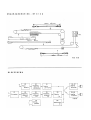
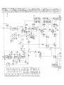
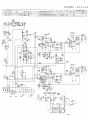
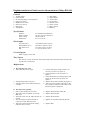
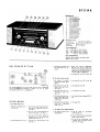
English translation of Dutch service information for Philips B7X14A
Controls
1
2
3
4
5
6
7
8
Volume adjust
On/off switch
PU switch (pickup or record player)
Long wave switch
Medium wave switch
Short wave switch
FM switch
Tuning knob
9
10
11
12
13
14
15
16
Bass adjust
Treble adjust
Tone switch
Tone switch
Reverb switch
Stereo switch
Mono switch
Balance
Specifications
Speakers
Mains voltages
Power rating
Dimensions
2 x AD3800 AM (800 ohm)
110-127-145-165-220-245 V
100 W at 220 V
27 x 71 x 29 cm
Wavelengths
LG (long wave)
MG (medium wave)
KG (short wave)
FM
1150-2000 m (260-150 kc/s)
185-580 m (1622-517 kc/s)
16.5-50.8 m (18.2-5.9 kc/s)
3-3.43 m (100-87.5 mc/s)
Circuit diagram
Refer to page 179 and 180.
Tube Layout
The fuse Z1 can also be located on the bottom left side of the transformer instead of the
top left side as shown here.
Malfunctions
A The radio does not work
1 Tubes and lamps do not glow
2 Tuning indicator does not glow
3 Tuning indicator reacts when tuning into
a station
B The radio works partially
1 Left or right speaker has no sound
2 The radio works on FM but not on LW,
MW, SW
3 The radio works on LW, MW, SW but not
on FM
4 The record player input works but no
reception on LW, MW, SW, FM
5 The radio works normal but the tuning
indicator does not work
a. Check if the mains voltage switch is set
correctly (see item 1 in figure 1)
b. Check if the fuse is ok (see item 2 in
figure 1)
c. Check if the tubes are seated properly and
if they are in the correct position (see
figure 1)
a. Replace the rectifier tube B9 (see figure 1)
a. Attach a second speaker (800 ohm) to the
extra speaker connector (if the radio works
then the speaker is defective)
a. Replace B6 and/or B7 and/or B8
a. Replace B2 and/or B4
a. Replace B1 and/or B5
a. Replace in sequential order B2, B3, B4
a. Replace B10
C The radio works unreliably
1 The radio crackles and/or is intermittent
a. Follow the directions mentioned in A-1
b. Check if the antenna-ground connectors
making good contact
c. Check if the symptom can be resolved by
replacing tubes in sequence
Block diagram
B2 Mixer
B3 IF amplifier
LW MW SW
B4 detector
LW MW SW
B1 FM unit
B2 IF amplifier
FM
B3 IF amplifier
FM
B9 Power
Supply
B6-B7 Audio
Amplifier
B4 IF amplifier
FM
B5 detector
FM
B10 Tuning
indicator
Special thanks are due to Jef Collin for this translation
B6-B8 Audio
Amplifier