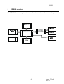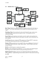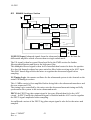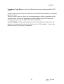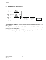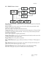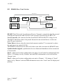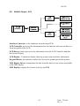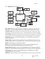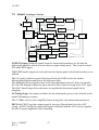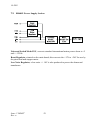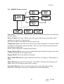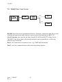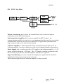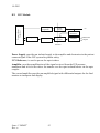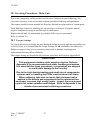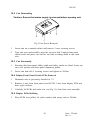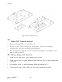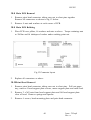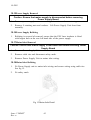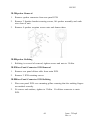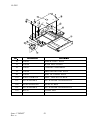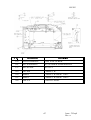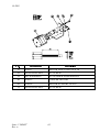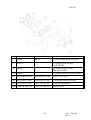
1
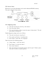
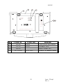
BABY DOPPLEX 4000®, BABY DOPPLEX 4002®
CUSTOMER SUPPORT DOCUMENTATION
SERVICE MANUAL
Part number 614365
Issue 2, January 2000
Huntleigh Diagnostics Ltd
Service Dept
35 Portmanmoor Road
Cardiff UK. CF24 5HN
Tel: (029)20496793 (24 hrs)
Fax: (029)20492520
E-mail: [email protected]
The information contained in this publication may not be used for any purpose other than that for which it was originally supplied.
The publication may not be reproduced in part or in whole without written consent.
Huntleigh Diagnostics Ltd products are subject to continuous development and consequently may incorporate minor changes from
the information contained in this manual.
The equipment and its accessories must be used strictly in accordance with the procedures detailed in this manual. The
manufacturer and its subsidiaries cannot accept any liability for loss or any indirect or consequential damages resulting from
misuse of, or modification to, the equipment or from operator negligence.
®Dopplex and 'H' logo are registered trade marks of Huntleigh Technology PLC
©Huntleigh Technology PLC 2000
614365
Table of Contents
1 General Information . . . . . . . . . . . . . . . . . . . . . . . . . . . . . 1
1.1 Introduction
. . . . . . . . . . . . . . . . . . . . . . . . . . . . . . 1
1.2 Servicing Policy
. . . . . . . . . . . . . . . . . . . . . . . . . . . . 1
1.3 Product Description
. . . . . . . . . . . . . . . . . . . . . . . . . . 1
1.4 Antistatic Handling, Electro Static Discharge (ESD) . . . . . . . . . . 2
1.5 Construction . . . . . . . . . . . . . . . . . . . . . . . . . . . . . . 2
2 Safety Aspects . . . . . . . . . . . . . . . . . . . . . . . . . . . . . . . . 3
2.1 Safety
. . . . . . . . . . . . . . . . . . . . . . . . . . . . . . . . . 3
2.2 Safety Testing
. . . . . . . . . . . . . . . . . . . . . . . . . . . . . 3
2.3 FECG Testing
. . . . . . . . . . . . . . . . . . . . . . . . . . . . . 4
2.4 Cleaning
................................5
2.5 Preventative Maintenance . . . . . . . . . . . . . . . . . . . . . . . 6
2.6 CE marking. . . . . . . . . . . . . . . . . . . . . . . . . . . . . . . 6
3 Functional Testing . . . . . . . . . . . . . . . . . . . . . . . . . . . . . . 7
3.1 BD4000, BD4002 Main Unit . . . . . . . . . . . . . . . . . . . . . . 7
3.2 Ultrasound Transducers . . . . . . . . . . . . . . . . . . . . . . . . 7
3.3 Toco
. . . . . . . . . . . . . . . . . . . . . . . . . . . . . . . . . . 8
3.4 FECG Functional Testing. . . . . . . . . . . . . . . . . . . . . . . . 9
3.5 Twins Functional Testing - BD4000
. . . . . . . . . . . . . . . . . . 9
3.6 Twins Functional Testing - BD4002 . . . . . . . . . . . . . . . . . . 11
4 Specification. . . . . . . . . . . . . . . . . . . . . . . . . . . . . . . . . 12
5 Technical Description. . . . . . . . . . . . . . . . . . . . . . . . . . . . 14
5.1 The Doppler Principle . . . . . . . . . . . . . . . . . . . . . . . . . 14
5.2 Doppler Audio Processing
. . . . . . . . . . . . . . . . . . . . . . 14
5.3 Heart Rate Processing . . . . . . . . . . . . . . . . . . . . . . . . 15
5.4 Fetal Movement Detection (FMD)
. . . . . . . . . . . . . . . . . . 15
5.5 FECG . . . . . . . . . . . . . . . . . . . . . . . . . . . . . . . . . 15
5.6 IUP . . . . . . . . . . . . . . . . . . . . . . . . . . . . . . . . . . 15
6 BD4000 overview . . . . . . . . . . . . . . . . . . . . . . . . . . . . . . 16
6.1 BD4000 Micro Section . . . . . . . . . . . . . . . . . . . . . . . . 17
6.2 BD4000 Analogue Section
. . . . . . . . . . . . . . . . . . . . . . 18
6.3 BD4000 Power Supply Section . . . . . . . . . . . . . . . . . . . . 20
Issue: 2 DRAFT
Rev: a
i
614365
6.4 BD4000 Printer Section . . . . . . . . . . . . . . . . . . . . . . . . 21
6.5 BD4000 Rear Panel Section
. . . . . . . . . . . . . . . . . . . . . 22
6.6 BD4000 Front Panel PCB. . . . . . . . . . . . . . . . . . . . . . . 23
7 BD4002 overview . . . . . . . . . . . . . . . . . . . . . . . . . . . . . . 24
7.1 BD4002 Micro Section . . . . . . . . . . . . . . . . . . . . . . . . 25
7.2 BD4002 Analogue Section
. . . . . . . . . . . . . . . . . . . . . . 26
7.3 BD4002 Power Supply Section . . . . . . . . . . . . . . . . . . . . 28
7.4 BD4002 Printer Section . . . . . . . . . . . . . . . . . . . . . . . . 29
7.5 BD4002 Rear Panel Section
. . . . . . . . . . . . . . . . . . . . . 30
7.6 BD4002 Front Panel PCB. . . . . . . . . . . . . . . . . . . . . . . 31
8 BD4000/BD4002 Transducers . . . . . . . . . . . . . . . . . . . . . . . 32
8.1 US1 Ultrasound Transducer
8.2 FECG Leg Plate
. . . . . . . . . . . . . . . . . . . . . 32
. . . . . . . . . . . . . . . . . . . . . . . . . . . 33
8.3 IUP Module . . . . . . . . . . . . . . . . . . . . . . . . . . . . . . 34
9 Electrostatic Discharge (ESD) Precautions . . . . . . . . . . . . . . . . 35
9.1 What is Static Electricity? . . . . . . . . . . . . . . . . . . . . . . . 35
9.2 Protective Measures . . . . . . . . . . . . . . . . . . . . . . . . . 35
10 Servicing Procedures - Main Unit. . . . . . . . . . . . . . . . . . . . . 36
10.1 Torque Settings . . . . . . . . . . . . . . . . . . . . . . . . . . . 36
10.2 Unit Dismantling
. . . . . . . . . . . . . . . . . . . . . . . . . . 37
10.3 Unit Reassembly
. . . . . . . . . . . . . . . . . . . . . . . . . . 37
10.4 Display/Front Panel Switch PCBs Removal . . . . . . . . . . . . . 37
10.5 Display PCBs Refitting
. . . . . . . . . . . . . . . . . . . . . . . 37
10.6 Display PCB Metalwork Removal . . . . . . . . . . . . . . . . . . 38
10.7 Refitting Display PCB Metalwork . . . . . . . . . . . . . . . . . . 39
10.8 Main PCB Removal . . . . . . . . . . . . . . . . . . . . . . . . . 40
10.9 Main PCB Refitting
. . . . . . . . . . . . . . . . . . . . . . . . . 40
10.10 Print Head Removal . . . . . . . . . . . . . . . . . . . . . . . . 40
10.11 Print Head Refitting. . . . . . . . . . . . . . . . . . . . . . . . . 41
10.12 Print Head Alignment Procedure . . . . . . . . . . . . . . . . . . 41
10.13 Stepper Motor Removal . . . . . . . . . . . . . . . . . . . . . . 42
10.14 Stepper Motor Refitting. . . . . . . . . . . . . . . . . . . . . . . 42
10.15 Power Supply Removal
. . . . . . . . . . . . . . . . . . . . . . 44
10.16 Power Supply Refitting . . . . . . . . . . . . . . . . . . . . . . . 44
ii
Issue: 2 Draft
Rev: a
614365
10.17 Mains Inlet Removal . . . . . . . . . . . . . . . . . . . . . . . . 44
10.18 Mains Inlet Refitting
10.19 Speaker Removal
. . . . . . . . . . . . . . . . . . . . . . . . 44
. . . . . . . . . . . . . . . . . . . . . . . . . 45
10.20 Speaker Refitting . . . . . . . . . . . . . . . . . . . . . . . . . . 45
10.21 Rear Panel Connector PCB Removal . . . . . . . . . . . . . . . 45
10.22 Rear Panel Connector PCB Refitting
. . . . . . . . . . . . . . . 45
10.23 Paper Tray Open Microswitch Removal . . . . . . . . . . . . . . 46
10.24 Paper Tray Open Microswitch Refitting
. . . . . . . . . . . . . . 46
10.25 Paper Tray Removal . . . . . . . . . . . . . . . . . . . . . . . . 46
10.26 Paper Tray Refitting . . . . . . . . . . . . . . . . . . . . . . . . 47
10.27 Paper Width Microswitch Removal . . . . . . . . . . . . . . . . . 47
10.28 Paper Width Microswitch Refitting . . . . . . . . . . . . . . . . . 47
10.29 Front Panel Connector Assembly Removal . . . . . . . . . . . . 47
10.30 Front Panel Connector Assembly refitting . . . . . . . . . . . . . 47
10.31 Toco/Ultrasound Transducer Dismantling . . . . . . . . . . . . . 47
10.32 Reassembly of Toco/Ultrasound Transducer. . . . . . . . . . . . 48
10.33 Strain Gauge Assembly Removal . . . . . . . . . . . . . . . . . 48
10.34 Strain Gauge Assembly Refitting. . . . . . . . . . . . . . . . . . 48
10.35 Toco Transducer Alignment . . . . . . . . . . . . . . . . . . . . 49
10.36 Replacing Transducer Cable . . . . . . . . . . . . . . . . . . . . 52
10.37 FECG Transducer Servicing . . . . . . . . . . . . . . . . . . . . 53
11 Fault Finding . . . . . . . . . . . . . . . . . . . . . . . . . . . . . . . . 53
11.1 Error Codes . . . . . . . . . . . . . . . . . . . . . . . . . . . . . 55
11.2 Service Notes . . . . . . . . . . . . . . . . . . . . . . . . . . . . 56
11.3 Displaying Status
11.4 Print Head Test
. . . . . . . . . . . . . . . . . . . . . . . . . . 56
. . . . . . . . . . . . . . . . . . . . . . . . . . . 57
11.5 Bed number . . . . . . . . . . . . . . . . . . . . . . . . . . . . . 57
11.6 Real time clock battery
. . . . . . . . . . . . . . . . . . . . . . . 57
11.7 Address . . . . . . . . . . . . . . . . . . . . . . . . . . . . . . . 57
12 Spare Parts List . . . . . . . . . . . . . . . . . . . . . . . . . . . . . . 58
12.1 Recommended Spare Parts . . . . . . . . . . . . . . . . . . . . . 58
13 Warranty And Service . . . . . . . . . . . . . . . . . . . . . . . . . . . 70
14 Overseas Offices. . . . . . . . . . . . . . . . . . . . . . . . . . . . . . 71
15 Appendices. . . . . . . . . . . . . . . . . . . . . . . . . . . . . . . . . 72
Issue: 2 DRAFT
Rev: a
iii
614365
15.1
Appendix A
15.2 Appendix B
. . . . . . . . . . . . . . . . . . . . . . . . . . . . . 72
. . . . . . . . . . . . . . . . . . . . . . . . . . . . . 73
iv
Issue: 2 Draft
Rev: a
614365
1
1.1
General Information
Introduction
This service manual provides the technical information required for repair and
maintenance of the Huntleigh Diagnostics Baby Dopplex 4000 and Baby Dopplex
4002.
1.2
Servicing Policy
Due to the nature of static-sensitive surface-mount technology, specialised equipment
and training is required when working on the surface mounted components used within
this product.
For this reason circuit diagrams are not included in this manual. Block diagrams and
fault finding sections are included to make fault finding to leaded component level
possible.
Units within the warranty period must not be dismantled and should be returned to
Huntleigh Diagnostics for repair. Any units returned showing signs of tampering or
accidental damage will not be covered under the warranty (refer to user manual for
further details).
1.3
Product Description
General
The Baby Dopplex 4000 and Baby Dopplex 4002 comprise a main unit (which
can be either free-standing, trolley or wall-mounted), two transducers (US* and
Toco). A patient event marker and a FECG legplate (optional). *BD4002 is
supplied with 2 US transducers.
Main Unit
This houses the printer and electronic circuitry - digital and analogue signal
processing, audio, display and power supply systems.
Signals from the transducers are processed and displayed on the large LED
displays. The ultrasound signal is also amplified, and output via the integral
loudspeaker. A volume control provides adjustment of sound level as required.
Processing for the FECG signal is also included.
A liquid crystal display (LCD) displays the system menu and other
information. Various parameters can be selected and/or changed as necessary
using the adjacent controls.
Also mounted on the control panel are controls for volume up/down, print
start/stop, Toco zero and clinical event marker.
Issue: 2 DRAFT
Rev: a
1
614365
Transducers
The transducer connectors are colour coded to indicate function: the
US/FECG connector is red, the Toco connector is blue.
The transducers are held in place by elasticated straps.
Patient Event Marker
This is a hand-held push-button which is pressed by the patient when she
feels fetal or uterine activity.
F
1.4
The patient and clinical event markers are distinguished from each
other on the paper, patient at the bottom of the FHR grid and
clinical at the top.
Antistatic Handling, Electro Static Discharge (ESD)
The Baby Dopplex uses Electrostatic Discharge Sensitive Devices (ESD's) in its
manufacture. The damage they suffer when handled incorrectly may be catastrophic.
More often and potentially even worse, the damage may be partial or latent, seriously
impairing the reliability of the unit.
Due to the nature of the components used within the Baby Dopplex, special
precautions must be taken to avoid damage to the circuitry. Static damage may not
be immediately evident but could cause premature failure.
The Baby Dopplex must only be dismantled and serviced within an ESD protected
area (EPA) as defined by CECC00015 (published by CENELEC) to avoid damage to
the assemblies.
1.5
Construction
The main unit comprises five PCB's, the main PCB, display PCB, PSU, end of paper
PCB and rear panel connector PCB. All boards with the exception of the PSU are
populated with surface mounted components.
The toco transducer consists of a termination PCB and a strain gauge.
The ultrasound transducer contains a single PCB, a multi element piezo crystal array
and a circular termination PCB.
The FECG transducer contains a single PCB and isolation amplifier with two scalp
electrode connections and a legplate disk for a maternal connection.
All electromechanical and through hole components are serviceable using standard
tools and soldering techniques, provided that anti-static precautions are always taken.
Recommended servicing is limited to replacement of assemblies detailed in this
manual.
2
Issue: 2 Draft
Rev: a
614365
2
Safety Aspects
2.1
Safety
q
The Baby Dopplex and its transducers are designed to high standards of
performance, reliability and safety.
q
Functional and safety checks should always be made after carrying out any
repairs or dismantling the equipment.
It is recommended that regular inspections are to be made to check the integrity of the
unit, and to ensure cables are not showing any signs of wear or noise when flexed.
2.2
Safety Testing
Using suitable safety test equipment, refer to the following guidelines.
Earth Bonding Test points
a)
Test the exposed chassis, accessible through the moulding apertures on the
underside of the unit.
b)
Test the metal shroud of the toco socket.
c)
Test the shells of the rear panel D-type connectors.
The maximum allowable reading at all points is 0.1W .
Earth Leakage Test
Set the on/off switch on the rear of the unit to the on position.
The maximum allowable leakage current is 100 m A.
Breakdown Test
Set the on/off switch on the rear of the unit to the “on” position.
Apply 1500Vac to the mains connector, connecting the low voltage probe to the
“EARTH” terminal. Firstly test the “LIVE” terminal and then the “NEUTRAL” for 60
seconds each. The maximum allowable reading is 1mA.
Issue: 2 DRAFT
Rev: a
3
614365
2.3
FECG Testing
Apply 1500Vac between the;
a)
chassis earth and leg electrode plate
b)
instrument live terminal and FECG terminals
c)
instrument neutral terminal and FECG terminals
The maximum allowable reading being 10m A over 60 secs.
Caution
Do not apply test voltages to main unit FECG input socket directly
If you require any assistance with safety testing your Huntleigh Diagnostics
equipment, contact Huntleigh Diagnostics. For the U.K. refer to the Health
Equipment Information Document No 95 – Code Of Practice For Acceptance Testing
Of Medical Equipment.
The following safety summary should be read before operating or carrying out any of
the procedures described in this manual:
Cautions
q
Do not use the Baby Dopplex in the presence of flammable gases such as
anaesthetic agents.
q
This product is not designed for sterile use. Do not use in the sterile field unless
additional barrier precautions are taken.
Do not
-
immerse main unit in any liquid. See section 2.4.
use solvent cleaners.
use high temperature sterilising processes (such as autoclaving).
use E-beam or gamma radiation sterilisation.
4
Issue: 2 Draft
Rev: a
614365
2.4
Cleaning
Caution
Switch the unit off and disconnect from the mains before cleaning
Main Unit
If required, this can be wiped with a soft cloth dampened with a
mild detergent, avoiding the connectors. Do not allow any fluid
to seep into the connectors. Do not allow any fluid to seep into
the unit.
Ensure the unit is completely dry before reconnecting to the
mains.
Ultrasound
Transducer
and FECG
Leg Plate
These should be cleaned by immersing in warm (50oC max.), mild
detergent solution, using a bottle brush if necessary. Do not
soak,or run under a tap. Rinse with clean water and dry
thoroughly before use.
F
Do NOT immerse connectors
Caution
Phenolic or detergent based disinfectants containing cationic
surfactants, ammonia based compounds, or antiseptic solutions such as
Stericol or Hibiscrub should never be used on any part of the system as
permanent damage will result.
Contractions
Transducer
(toco)
Belts
Wipe with a soft cloth dampened with a mild detergent solution,
avoiding the connector. Do not allow any fluid to seep into the
transducer. Dry thoroughly before use.
These may be hand-washed at 40oC max., using a mild detergent
solution. Rinse with clean water and dry thoroughly (without using
heat) before use.
Disinfection
Transducers and Leg Plate Only.
To assist with disinfection, wipe the transducers and leg plate
with a soft cloth dampened with sodium hypochlorite 1000ppm,
and wipe dry.
Please be sure to check your local infection control policies or
equipment cleaning procedures.
Issue: 2 DRAFT
Rev: a
5
614365
2.5
Preventative Maintenance
The Huntleigh Diagnostics Baby Dopplex 4000 and Baby Dopplex 4002 are
designed for a minimum amount of maintenance. To support the high standard of
performance and safety, the safety and functional checks should be carried out as part
of a regular maintenance routine.
Refer to the user manual for details of connection of cables and accessories, and also
for the correct setting of controls which may have been altered during maintenance.
No attempt should be made to service the unit unless adequate workshop facilities
and suitable staff are available.
2.6
CE marking
All rework procedures detailed in this service manual must be strictly adhered to, to
ensure continuing compliance with EC Directive 93/42/EEC.
Any rework routine carried out outside the scope of this manual may result in the
equipment no longer meeting this specification and the rework organisation will be
responsible for this non-conformance.
6
Issue: 2 Draft
Rev: a
614365
3
3.1
Functional Testing
BD4000, BD4002 Main Unit
Switch the unit on by pressing the on/off switch at the back of the unit to the “on”
position(I).
The Baby Dopplex displays will illuminate and you will hear a click from the
loudspeaker. The message “Huntleigh Diagnostics” appears for an instant while the
unit carries out a self-test.
Inspect the transducer cables and plugs for signs of damage and physical condition of
the transducers.
The ultrasound transducer face should be free from marks and the toco boot
undamaged. Remove any gel from the transducers if present.
Open printer tray, unit should display “Paper tray open” and remove paper pack.
Close paper tray, unit should display “End of paper”. Refit paper pack ensuring that the
shiny side is uppermost. This sensitive side can be easily marked with a fingernail.
Plug in the ultrasound, toco and event marker transducers, set the printer to 3cm/minute
(menu option) and start the unit printing.
Press the patient event marker switch and observe the arrow at the bottom of the
printout.
Press the clinical event marker on the display panel and an arrow should appear at the
top of the printout.
Increase the volume using the up/down controls on the front panel and flex cable on the
ultrasound transducer at the transducer and plug ends checking that no crackling is
heard.
Replace the ultrasound transducer with the FECG leg plate. The unit should fast feed
for a few seconds if the printer is still running when the ultrasound transducer is
removed, and then continue printing.
Ensure that the FECG text appears at the bottom of the FHR scale on the trace.
3.2
Ultrasound Transducers
Reconnect the ultrasound transducer and input a signal by placing it in the palm of the
hand and stroke the back of the hand approximately twice per second.
The display should indicate a rate of around 120 BPM after a few seconds. Continue
this for one minute and check for a corresponding line on the fetal heart rate trace.
F
Too strong a signal from an adult heart can overload the unit and
result in false counting.
Issue: 2 DRAFT
Rev: a
7
614365
The signal quality will vary during this test and can be observed in the top right hand
corner of the LCD display. The four bands are illuminated for a good signal and
progressively extinguish as the signal deteriorates. Repeat for FHR1 and FHR2
inputs using front panel to select audio channel (BD4002 only).
3.3
Toco
Place the toco transducer on a solid surface with the rubber boot uppermost and level.
Press the zero button on the front panel. Holding the toco transducer steady, flex the
cable at the transducer and plug ends. Check the UA loading display and printout to
ensure that there is no deviation from the zero line.
Depress the toco rubber boot gently and release, repeat this several times. Check that
the UA display registers the change and returns to zero after a short delay.
With the rubber boot still uppermost and level, reset the zero then place a 100g
weight in the centre of the boot.
The shape of this weight is important and the contact area on the rubber boot should
be 12mm diameter maximum. The UA display should indicate 80% +/-5%.
FECG Mode
Ultrasound Mode
8
Issue: 2 Draft
Rev: a
614365
Remove the weight after 30 seconds check for return to zero and turn the printer off, the
printer should fast feed a blank section.
Compare the printout with the examples shown above, checking for print quality,
date/time stamp, event markers, ultrasound, toco trace and mode (i.e. US/FECG).
3.4
FECG Functional Testing
Reconnect the FECG legplate. Connect the patient terminals to an Fetal ECG simulator
setting the voltage to between 25m V and 2mV. Only one FECG transducer can be used
at any one time. Use of an adult ECG simulator may cause erroneous readings.
The ECG rate should be set between 30-240 and checked across its range.
3.5
Twins Functional Testing - BD4000
Connect two BD4000 units together using the connection lead supplied with the twins
kit. The monitor with the cable end marked '1' causes the unit to be the LOCAL unit
while the other unit defaults to REMOTE.
The display on the LOCAL BD4000 should display “Remote FHR =” in the top line of
the text display.
Connect an ultrasound transducer to both units and input a signal on the REMOTE unit
by stroking the ultrasound transducer.
The REMOTE unit LCD should display 'Twins Remote Unit' and the printer should be
inoperative.
The FHR should be displayed on both the REMOTE LED and LOCAL LCD displays.
Set the printer on the LOCAL unit to print and with a signal to the REMOTE unit, a
corresponding trace should be printed.
When full width paper(210mm) is loaded, the LOCAL unit will print two FHR grids
one above the other and one toco trace.
With the normal paper(150mm) fitted, the two FHR traces are overlaid on one grid, and
identified periodically by the letters 'R' and 'L'.
Issue: 2 DRAFT
Rev: a
9
614365
150mm paper(normal)
210mm paper(wide)
10
Issue: 2 Draft
Rev: a
614365
3.6
Twins Functional Testing - BD4002
Fit both US transducers and toco transducer and test as detailed in section 3.2.
Only one FECG transducer can be used at any one time and should be tested as detailed
in section 3.4.
When full width paper(210mm) is loaded, the unit will print two FHR grids one above
the other and one toco trace.
With the normal paper(150mm) fitted, the two FHR traces are overlaid on one grid, and
identified periodically.
Issue: 2 DRAFT
Rev: a
11
614365
4
Specification
General
Product Name:
Model No:
Baby Dopplex 4000/Baby Dopplex 4002
BD4000/BD4002
Physical
Size - control unit:
Weight:
93mm x 380mm x 250mm (HxWxD)
4.5Kg
Environmental
Operating Temperature:
Storage Temperature:
+10oC to +30oC
-10oC to +40oC
Electrical
Power Supply:100-250V a.c. 50/60Hz
Fuse Type:
T2A 250V
Audio Power:
1 Watt max
Ultrasound Transducer
Transmitter frequency:
Acoustic Output:
US1 - 1.5MHz +/-1%
Under the requirements laid down in IEC1157:
1992, the peak negative acoustic pressure does
not exceed 1MPa. the output beam intensity
does not exceed 20mW/cm2 and the
spatial-peak temporal-average intensity does not
exceed 100mW/cm2.
Contractions Transducer
Range:
Max. Load:
0 to 100% relative units.
300g.
Regulatory Compliance/Standards
Complies with:
BS5724 : Part 1 : 1989
IEC601-1 : 1988
EN60601-1 : 1990
12
Issue: 2 Draft
Rev: a
614365
EN60601-1 Classification:
Type of shock protection - Class I
Degree of shock protection - Type B
Leg Plate & IUP Module Type BF
Protection Against
Water Ingress
Ordinary equipment
Degree of Safety in PresenceNot suitable for use in the presence of
of Flammable Gases:
flammable gases.
Mode of Operation:
Continuous
Performance
FHR Range:
US
50 to 210 BPM
FECG 30 to 240 BPM
FHR Accuracy:
FHR Scale Options:
+/- 1BPM over full range.
50 to 210 BPM at 20 BPM/cm,
30 to 240 BPM at 30 BPM/cm.
Medical Devices Directive 93/42/EEC
Issue: 2 DRAFT
Rev: a
13
614365
5
5.1
Technical Description
The Doppler Principle
The Baby Dopplex uses the Doppler principle for non-invasively monitoring
movement within the body.
The Doppler principle states that if a signal is transmitted at a fixed frequency and is
reflected by a moving body, the frequency of the received signal will be shifted. An
increase in frequency results if the reflector is moving towards the
transmitter/receiver, and a decrease results if moving away from the
transmitter/receiver. The amount of frequency shift is proportional to the velocity of
the reflector relative to the transmitter/receiver.
In the Dopplex range, a fixed frequency ultrasonic signal is transmitted from the
transducer into the body. This is reflected from, for example, the fetal heart. The
signal is reflected from the heart and is received by the transducer. Due to the
movement of the fetal heart, a frequency shift results, which is proportional to the
fetal heart velocity.
5.2
Doppler Audio Processing
The Baby Dopplex ultrasound transducer contains a transmitter and receiver. In use,
the transducer sends out a pulsed ultrasonic signal, generated by the piezo-ceramic
transmitter crystals, at 1.5 MHz.
This signal is scattered by blood cells or any other “interface” such as skin, muscle
layers, organs, walls of vessels etc. A small proportion of the scattered signal will be
reflected back and detected by the receiver.
By demodulating the received signal (removing the high frequency carrier) the
Doppler shifted component (i.e. the difference between the transmitted and received
signals) can be produced.
With typical target velocities found in the human body, this Doppler shift signal falls
within the audio frequency range. It can therefore simply be amplified and heard
through a loudspeaker.
It is important to remember that the sound you hear is an artificial sound, the
frequency (pitch) of which is proportional to the velocity of the moving target.
It is not the real sound made by the fetal heart.
14
Issue: 2 Draft
Rev: a
614365
5.3
Heart Rate Processing
The Doppler audio signal is amplified and filtered. It's amplitude is then regulated after
passing through a low-pass anti-aliasing filter. The signal is then sampled by the
microcontroller in order to calculate the fetal heart rate.
5.4
Fetal Movement Detection (FMD)
The BD4000 and BD4002 will annotate the fetal heart trace towards the top of the
contraction channel when a fetal movement is detected.
This movement is derived from low frequency Doppler signals from the Ultrasound
Transducer.
The FMD can be enabled via the front panel and its sensitivity set.
Refer to the user manual for further information.
5.5
FECG
As an alternative to using ultrasound to monitor FHR, a FECG scalp electrode may be
used.
This makes a direct connection to the fetal scalp and provides more reliable tracking of
the fetal heart rate during the later stages of labour.
The FECG transducer incorporates an isolation amplifier which provides electrical
isolation between the patient and the monitor.
5.6
IUP
In some markets Intra Uterine Pressure measurements are made as an alternative to the
external Toco transducer supplied as standard.
Patient electrical isolation is provided by an adaptor box plugged into the Toco socket
and a corresponding waveform is printed on the contractions trace either shown in
millimetres of Mercury (mmHg) or kiloPascals (kPa).
The pressure sensor is either inserted directly into the mother using the Intran Plus IUP
400 Disposable IUP System (Utah Medical Products inc). Alternatively using the
SensoNor SP844 pressure sensor and a saline filled catheter system. Refer to user
manual for further information.
Issue: 2 DRAFT
Rev: a
15
614365
6
BD4000 overview
The BD4000 has been split up into several sections as shown below for clarity.
16
Issue: 2 Draft
Rev: a
614365
6.1
BD4000 Micro Section
Real Time Clock, this enables the micro to display and print the date/time on
the trace. User setup information is held within the internal memory of the
clock.
Watchdog Timer, this monitors the micro and checks for any system errors.
Upon detecting a system error the micro is reset. All controls revert to
switch-on settings.
Event Marker, this patient event marker records a mark on the printout in a
different place from the clinical event marker accessed via the front panel (see
user manual).
Serial Ports, the rear connector PCB supports two D-type RS232 connectors
for external interfacing and twins mode communication.
Display PCB, is mounted on the top half of the case moulding and consists of
two separate PCBs joined by a short ribbon cable. This PCB also carries the
system controls.
ROM, the ROM memory contains the program.
RAM, the main PCB has three RAM IC's, two are used on the Digital Signal
Processing section and the third for data processing by the micro.
Digital Signal Processor, processes the information from the ultrasound and
ECG transducers implementing autocorrelation and ECG detection for deriving
the FHR.
Issue: 2 DRAFT
Rev: a
17
614365
DSP Bootup, this circuitry loads the DSP program from EPROM to the DSP’s
internal RAM when the unit is reset.
EEPROM, used for storage of user setup information when the unit is switched off.
Twins Detect, a link in the cable sets the monitor to twins mode.
18
Issue: 2 Draft
Rev: a
614365
6.2
BD4000 Analogue Section
Power
Amplifier
Volume
Control
Microcontroller
Gain
Control
Anti Alias
Filter
AGC
FMD
Band Pass
Filter
Low Pass
Filter
Differential
Amplifier
US
US/FECG
Input
FECG
Low Pass
Filter
FECG Wideband
Transducer
Type Detect
Osc
Serial Ports
SYNC/
Gate
US
Timing
Logic
RF
Amplifier
1.5MHz
SYNC/Gate
Differential
Amplifier
Transducer
Type Detect
TOCO /
IUP Input
US/FECG Input, balanced signals from the ultrasound transducer are fed into the
differential amplifier which converts them to single ended mode.
The US signal is then low-pass filtered and fed to the FMD section for further
filtering/amplification and also to the high-pass filter.
This bandpass filtered signal is then level controlled then boosted to drive the speaker.
It is also fed through a sharp low-pass anti-alias filter before arriving at the AGC input.
This DAC based stage allows the micro to regulate the ultrasound signal before
sampling.
US Timing Logic, the master oscillator for the ultrasound system is also located on the
main PCB analogue section.
This 1.5MHz carrier is first amplified before being fed to the ultrasound transducer and
the rear connector PCB.
The timing logic controlled by the micro sets the ultrasound transmit timing and fully
synchronises the system in the twins ultrasound mode.
FECG, the FECG leg plate output signal is low-pass filtered then fed to the AGC
circuit. In FECG mode the ultrasound signal is disabled and the AGC used to regulate
the FECG signal amplitude before sampling.
An unfiltered version of the FECG leg plate output signal is also fed to the micro and
sampled.
Issue: 2 DRAFT
Rev: a
19
614365
Transducer Type Detect, is used to differentiate between ultrasound and FECG
modes.
A probe code circuit detects the connection of an ultrasound transducer and signals
this to the micro.
The micro then opens or closes the relevant analogue switches depending on the
mode selected, to route the appropriate signals through to the A/D converters.
A similar system is used to detect IUP/Toco transducers.
Toco/IUP Input, a differential amplifier converts the balanced output from the
transducer to single ended mode suitable for micro A/D sampling. A sense line
detects when an IUP system is connected.
20
Issue: 2 Draft
Rev: a
614365
6.3
BD4000 Power Supply Section
Universal Switch Mode PSU, converts standard international mains power down to +5
and +/-12Vdc.
Boost Regulator, situated on the main board, this converts the +12V to +26V for use by
the print head and stepper motor.
Low Noise Regulator, a low noise +/- 10V is also produced to power the ultrasound
transducer, anti aliasing filter and automatic gain control circuitry.
Issue: 2 DRAFT
Rev: a
21
614365
6.4
BD4000 Printer Section
Print Head, is a solid state thermal array of heater elements that print onto thermally
sensitive paper.
Strobe Control, the strobe control varies the strobe width to the print head, which
regulates the intensity of the printout.
The strobe width is controlled by the microprocessor.
Temperature Sense, this allows the micro to assess the temperature of the print head
by means of a thermistor in the print head. This will vary as the monitor prints and
with ambient temperature.
Strobe width is adjusted to regulate print density.
Stepper Motor Driver, processes the information from the data bus and converts this
to a form acceptable to the stepper motor.
Stepper Motor, drives the printer mechanism.
Paper Width Detector, the paper width switch detects if 150mm or 210mm paper is
fitted.
Paper Detector, this detects end of paper. The printer will stop and a message will
appear on the LCD when the paper tray is empty.
Tray Open Detector, detects when the paper tray is open and stops printing.
Both sides of the paper tray must be latched shut for normal printing.
22
Issue: 2 Draft
Rev: a
614365
6.5
BD4000 Rear Panel Section
Twins Detect
RS232
Carrier In
SYNC/Gate In
RS232
Carrier Out
SYNC/Gate Out
DUART, Dual Universal Asynchronous Receive Transmit, controls the data flow to and
from the microprocessor and converts it into a protocol accepted by the RS232 IC.
Level Converter, this converts the data from the DUART into RS232 voltage levels.
The RS232 link allows data to be passed from and to an external device via the rear
panel D-type connectors.
Twins Detect, detects when the twins lead connector marked '1' is connected, to place
the unit into twins mode (LOCAL).
The BD4000 connected to the other end of the twins cable becomes the REMOTE unit.
Synchronisation signals, synchronises the two ultrasound transducers when connected
in twins mode.
Port 1, when used in twins configuration sets unit to ‘Local’ mode by monitoring Twins
Detect. US timing is set by ‘Remote’ unit and FHR information is received from the
‘Remote’ unit.
Port 2, when used in twins configuration sets unit to ‘Remote’. US timing of ‘Local’
unit is set by ‘Remote’ unit and FHR information sent to the ‘Local’ unit for display and
printing.
Issue: 2 DRAFT
Rev: a
23
614365
6.6
BD4000 Display PCB
Interface Connector, is the connector from the main PCB.
LCD Controller, processes the information from the data bus and converts this to a
form acceptable to the LCD.
LCD Driver, further processes the information from the LCD Controller and data
bus for the Display.
LCD Display, 32 character display showing system setup and other information.
Keypad Matrix, this interface enables the user to set up and operate the monitor.
LED Display Driver, manipulates the data from the data bus into a form acceptable
to the LED display.
LED Displays, display the Uterine Activity and FHR.
24
Issue: 2 Draft
Rev: a
614365
7
BD4002 overview
The BD4002 has been split up into several sections as shown below for clarity.
Issue: 2 DRAFT
Rev: a
25
614365
7.1
BD4002 Micro Section
Real Time Clock, this enables the micro to display the date/time on the trace and
front panel. User setup information is held within internal memory of the clock.
Watchdog Timer, this monitors the micro and checks for any system errors. Upon
detecting a system error the micro is reset. All controls revert to switch-on settings.
Event Marker, this patient event marker records a mark on the printout in a different
place from the clinical event marker accessed via the front panel (see user manual).
Serial Ports, the rear connector PCB supports two D-type RS232 connectors for
external interfacing.
Display PCB, is mounted on the top half of the case moulding and consists of two
separate PCBs joined by a short ribbon cable. This also carries the system controls.
ROM, the ROM memory contains the program.
RAM, the main PCB has three RAM IC's, two are used on the Digital Signal
Processing section and the third for data processing by the micro.
Digital Signal Processor, processes the information from the ultrasound and ECG
transducers implementing autocorrelation and ECG detection for deriving the FHR.
DSP Bootup, this circuitry loads the DSP program from EPROM to the DSP's
internal RAM when the unit is reset.
EEPROM, used for storage of user setup information when the unit is switched off.
26
Issue: 2 Draft
Rev: a
614365
7.2
BD4002 Analogue Section
Anti Alias
Filter
AGC
Power
Amplifier
CH1
FMD
Volume
Control
Microcontroller
CH2
FECG
Low Pass
Filter
Anti Alias
Filter
Low Pass
Filter
FMD
CH1
CH2
Differential
Amplifier
Transducer
Type Detect
Probe
Detect
US
Differential
Amplifier
Low Pass
Filter
Gain
Control
AGC
Band Pass
Filter
Sync
Band Pass
Filter
FECG Wideband
Differential
Amplifier
US
US/FECG
Inputs
FECG
Low Pass
Filter
FECG Wideband
Transducer
Type Detect
CH1
CH2
US
Timing
Logic
TOCO /
IUP Input
RF
Amplifier
1.5MHz
SYNC/Gate
US/FECG Input, balanced signals from the ultrasound transducer are fed into the
differential amplifier which converts them to single ended mode. This is used on both
FH1 and FHR2 inputs.
FHR/FHR2 audio outputs are selected from the display panel when both transducers are
utilised
The US signal is then low-pass filtered and fed to the FMD section for further
filtering/amplification and also to the high-pass filter.
This bandpass filtered signal is then level controlled then boosted to drive the speaker.
It is also fed through a sharp low-pass anti-alias filter before arriving at the AGC input.
This DAC based stage allows the micro to regulate the ultrasound signal before
sampling.
US Timing Logic, the master oscillator for the ultrasound system is also located on the
main PCB analogue section.
This 1.5MHz carrier is first amplified before being fed to the ultrasound transducers.
FECG, the FECG leg plate output signal is low-pass filtered then fed to the AGC
circuit. In FECG mode the ultrasound signal is disabled and the AGC used to regulate
the FECG signal amplitude before sampling.
Issue: 2 DRAFT
Rev: a
27
614365
Transducer Type Detect, is used to differentiate between ultrasound and FECG
modes.
A probe code circuit detects the connection of an ultrasound transducer and signals
this to the micro.
The micro then opens or closes the relevant analogue switches depending on the
mode selected, to route the appropriate signals through to the A/D converters.
Probe Detect, detects the presence of one or two US/FECG transducers allowing the
micro to monitor the correct channels as required.
Toco/IUP Input, a differential amplifier converts the balanced output from the
transducer to single ended mode suitable for micro A/D sampling. A sense line
detects when an IUP system is connected.
A probe code circuit detects the connection of an external contractions or IUP
transducer and signals this to the micro.
28
Issue: 2 Draft
Rev: a
614365
7.3
BD4002 Power Supply Section
Universal Switch Mode PSU, converts standard international mains power down to +5
and +/-12Vdc.
Boost Regulator, situated on the main board, this converts the +12V to +26V for use by
the print head and stepper motor.
Low Noise Regulator, a low noise +/- 10V is also produced to power the ultrasound
transducers.
Issue: 2 DRAFT
Rev: a
29
614365
7.4
BD4002 Printer Section
Print Head, is a solid state thermal array of heater elements that print onto thermally
sensitive paper.
Strobe Control, the strobe control varies the strobe width to the print head, which
regulates the intensity of the printout.
The strobe width is controlled by the microprocessor.
Temperature Sense, this allows the micro to assess the temperature of the print head
by means of a thermistor in the print head. This will vary as the monitor prints and
with ambient temperature.
Strobe width is adjusted to regulate print density.
Stepper Motor Driver, processes the information from the data bus and converts this
to a form acceptable to the stepper motor.
Stepper Motor, drives the printer mechanism.
Paper Width Detector, the paper width switch detects if 150mm or 210mm paper is
fitted.
Paper Detector, this detects end of paper. The printer will stop and a message will
appear on the LCD when the paper tray is empty.
Tray Open Detector, detects when the paper tray is open and stops printing.
Both sides of the paper tray must be latched shut for normal printing.
30
Issue: 2 Draft
Rev: a
614365
7.5
BD4002 Rear Panel Section
RS232
RS232
DUART, Dual Universal Asynchronous Receive Transmit, controls the data flow to and
from the microprocessor and converts it into a protocol accepted by the RS232 IC.
Level Converter, this converts the data from the DUART into RS232 voltage levels.
The RS232 link allows data to be passed from and to an external device via the rear
panel D-type connectors.
Port 1, for connection to external devices, (e.g. NiBP/SpO2 monitors)
Port 2, used for communications with central monitoring stations.
Issue: 2 DRAFT
Rev: a
31
614365
7.6
BD4002 Display PCB
Interface Connector, is the connector from the main PCB.
LCD Controller, processes the information from the data bus and converts this to a
form acceptable to the LCD.
LCD Driver, further processes the information from the LCD Controller and data
bus for the Display.
LCD Display, 32 character display showing system setup and other information.
Keypad Matrix, this interface enables the user to set up and operate the monitor.
LED Display Driver, manipulates the data from the data bus into a form acceptable
to the LED displays.
LED Displays, display the Uterine Activity and FHRs.
32
Issue: 2 Draft
Rev: a
614365
8
8.1
BD4000/BD4002 Transducers
US1 Ultrasound Transducer
Timing Logic, is driven by the control and carrier signals fed from the main unit.
This logic controls the transmitter and receiver range gating.
5V Regulator, the 5V regulator is supplied from the +10V line.
Range Gate Control, is used to reject any unwanted signal caused by reflections and
contact noise.
Transmitter Output, the output is pulsed, the timing of which is controlled by the
timing logic section.
Range Gate Switching, the signal from the ultrasound head is selected by the range
gating section to ensure that the receiver circuitry is not enabled during the transmit
period, this is switched on after a suitable period to reduce unwanted signals.
Demodulator, a reference signal from the main oscillator is used to demodulate the
received signal.
Filter Network, the output from the demodulator is low pass filtered to remove any
unwanted noise.
Output Buffers, to minimise noise, a balanced output is used.
Ultrasound Faceplate, comprises a multi element array with 7 crystals connected in
parallel.
Issue: 2 DRAFT
Rev: a
33
614365
8.2
FECG Leg Plate
±
Patient Connections, these follow the standard three node connection pattern
commonly used in FECG monitoring.
Instrumentation Amplifier, this is used to amplify the FECG signal. An
instrumentation amplifier is used as it is very important that this stage has a very high
common mode rejection ratio due to the small FECG signal that is presented with
large common mode noise and maternal signals.
Isolation Amplifier, to maintain patient safety should an electrical fault occur, an
isolation amplifier is used as a barrier to avoid excess leakage through to the patient.
Power Supply, this is used to provide a 15V supply to the isolation amplifier. A +5V
supply is derived from the +10V input. The +5V supply is used in conjunction with
the -10V line to provide the isolation amplifier with the 15V required.
Signal Conditioning, is used to smooth and amplify the signal from the Isolation
amplifier for further processing by the main unit.
The unfiltered signal from the isolation amplifier is also provided.
34
Issue: 2 Draft
Rev: a
614365
IUP Module
Pressure Sensor
Connector
8.3
Tracking
Regulator
+5v
Power
Supply
2.5v
Reference
Amplifier
Driver
OptoCoupler
Amplifier
Differential
Outputs
Isolation
Power Supply, provides an isolated supply to the ampifier and electronics in the patient
connected part of the IUP system for patient safety.
2.5V Reference, is used to power the opto isolator.
Amplifier, provides amplification of the siganl recieved from the IUP pressure
transducer and is fed to the driver for transfer over the opto isolated barrier via the opto
coupler.
The second amplifier provides an amplified signal with differential outputs for the fetal
monitor to interprete and display.
Issue: 2 DRAFT
Rev: a
35
614365
9
9.1
Electrostatic Discharge (ESD) Precautions
What is Static Electricity?
Static electricity is generated when two materials move against one another. The
voltage generated depends on the materials generating the electricity, the speed of
movement, humidity and rate of discharge. All man made materials generate static,
such as plastic coffee cups, plastic bags, binders and folders, all of which are likely to
be within the working area.
Activity
10-20% Relative Humidity
Walking across carpet
35,000 Volts
Walking across vinyl floor
12,000 Volts
Working at bench
6,000 Volts
Plastic folder
7,000 Volts
Poly bag lifted from bench
20,000 Volts
Foam padded work chair
18,000 Volts
Static electricity is generated very easily, and is only felt by us when we discharge the
built up charge rapidly by touching a grounded object such as a grounded door
handle. The voltages felt by us are as high as 3kV, but only 20V is necessary to
damage some components. Voltages as high as 35kV and current spikes of 40A have
been known.
The damage to the component, or assembly can be immediate or latent. Latent
damage is not immediately obvious but can lead to the circuitry subsequently failing
or becoming erratic.
9.2
Protective Measures
To protect devices (ESDs) from the unwanted effects of ESD, two key measures must
be taken to minimise the possibility of damage.
1.
All sensitive devices and assemblies must be handled in an ESD Protected
Area (EPA).
2.
All sensitive devices and assemblies must be transported in a protected state.
For further information on static precautions and soldering equipment refer to
Appendix A.
36
Issue: 2 Draft
Rev: a
614365
10 Servicing Procedures - Main Unit
Due to the complexity of the product and the use of surface mount technology, the
electronic circuitry is not serviceable without specialised training and equipment.
The repairs detailed in this manual are therefore limited to replacement of certain parts.
Fault finding is limited to checking for the presence or absence of signals around
suspect components using an oscilloscope or multimeter.
Repairs should only be undertaken by suitably skilled service personnel.
Refer to section 2.6.
10.1 Torque Settings
To ensure that the case fixings are not damaged during servicing and that assemblies are
securely fixed, it is essential that the torque settings for all assemblies are adhered to.
Failure to torque fixing screws correctly may result in damage requiring case
replacement and may affect reliability.
The torque setting are detailed in the relevant procedure and listed in Appendix B.
CAUTIONS
This equipment contains static sensitive devices. Refer to
Appendix A for recommended anti-static handling precautions.
It is essential that these procedures, or equivalent, are adopted
to avoid static damage to the circuitry.
Due to the high density tracking and small size of components,
extreme care in handling the PCBs must be taken at all times.
When soldering, take care to ensure that minimum heat is
applied to the boards and components for the minimum time
necessary to ensure high quality joints. Inspect the area around
repairs for solder splashes and bridges. Refer to Appendix A for
details of recommended soldering procedures.
Issue: 2 DRAFT
Rev: a
37
614365
10.2 Unit Dismantling
Caution: Ensure that mains supply is removed before opening unit
Fig 5 Case Screw Removal
1.
Invert unit on a smooth surface and remove 5 case securing screws.
2.
Turn unit over and carefully raise the top case half. Unplug front panel
ribbon cable and place case half to one side, avoiding strain to the earth
wire.
10.3 Unit Reassembly
1.
Ensuring that front panel ribbon cable and safety earths are fitted, locate top
case over speaker and front panel alignment guides.
2.
Invert unit and refit 5 securing screws and tighten to 45cNm.
10.4 Display/Front Panel Switch PCBs Removal
1.
Dismantle unit as previously detailed in 7.2.
2.
Remove 6 nuts from front panel switch PCB, 3 nuts from display PCB and
their nylon washers.
3.
Carefully lift PCBs and earth wire (see Fig 11) clear from case assembly.
10.5 Display PCBs Refitting
1.
Place PCBs over pillars, fit nylon washers and torque nuts to 20cNm.
38
Issue: 2 Draft
Rev: a
614365
Fig 6 Front Panel Removal
10.6
Display PCB Metalwork Removal
1.
Remove Display PCBs as detailed in 7.4.
2.
Remove nylon washers and spacers from pillars. Remove remaining 4
retaining nuts and metal washers from metalwork.
3.
The front panel metalwork can now be pushed through case moulding cut-out
and the label removed.
10.7 Refitting Display PCB Metalwork
1.
With case top uppermost, place metalwork in cut-out.
2.
Turn case top over, fit metal washers, earth lead (see Fig 11) and securing nuts
as shown.
3.
Fit washers as Fig 11 and refit display PCBs as detailed in 7.5.
4.
Check switch caps, LCDs, LEDs are flush with metalwork, fit label.
Issue: 2 DRAFT
Rev: a
39
614365
10.8 Main PCB Removal
1.
Remove print head connector, taking care not to short pins together.
Remove all connectors as shown in fig 12 below.
2.
Remove 4 nuts and washers at each corner of PCB.
10.9 Main PCB Refitting
1.
Place PCB over pillars, fit washers and nuts as above. Torque retaining nuts
to 20cNm and fit shakeproof washer under earthing point nut.
Fig 12 Connector layout
2.
Replace all connectors as above.
10.10Print Head Removal
1.
Remove print head connector, taking care not to short pins. Pull out paper
tray, remove 4 head support plate screws, motor support plate and earth lead.
2.
Remove 2 x M3 nuts from head support plate and lift head support plate
clear of head. Remove springs and spacers.
3.
Remove 6 screws, head mounting plate and print head connector.
40
Issue: 2 Draft
Rev: a
614365
10.11Print Head Refitting
1.
Fit print head connector, head mounting plate and tighten 6 screws to 35cNm.
Ensure that print head is parallel to head mounting plate.
2.
Place spacers over pillars and springs over spacers.
3.
Place head support plate over head mounting plate ensuring that metal tongue
is located under screw head as fig 13.
4.
Push print head support plate past pillars, fit plain washers over pillars, tighten
nuts to 35cNm. Ensure that print head support plate and head mounting plate
are free to slide up and down spacers.
5.
Place print head assembly over mounting pillars and screws. Align print head
as detailed in 7.12.
10.12Print Head Alignment Procedure
Warning - Shock Hazard
Extreme caution must be taken while working in live
equipment, ensure that earthed case does not contact live
parts. Also note that parts of the power supply are live.
1.
With print head assembly screws tightened lightly and ribbon cable connected,
pull print head towards front of unit and close paper tray.
2.
Ensure that front panel ribbon cable is connected to main PCB and connect
mains supply to inlet socket.
Fig 13 Print Head Assembly
Issue: 2 DRAFT
Rev: a
41
614365
3.
Start unit printing at 3cm/minute and slide print head towards case rear until
print density is acceptable. Refer to 8.4 for setup test pattern.
4.
Remove mains supply and tighten head support plate screws to 35cNm.
10.13Stepper Motor Removal
1.
Disconnect stepper motor connector. Remove print head assembly as
detailed in 7.10 and cable ties to printhead securing plate.
2.
Remove stepper motor assembly clear of monitor. Remove stepper motor
mounting plate screws and remove mounting plate.
10.14Stepper Motor Refitting
1.
Fit Stepper motor to mounting plate, passing gear through mounting bracket
noting cable orientation and tighten screws to 60cNm.
2.
Insert stepper motor assembly to base, fit earth lead, motor support plate and
screws, tighten loosely. Secure cables using cable ties.
3.
Fit print head as per 7.11 and close paper tray.
4.
Align motor gears with roller gears ensuring gears mesh allowing small
amount of backlash, see fig 14.
5.
Tighten screws to 60cNm.
Fit stepper motor connector and align print head as per 7.12.
Fig 14 Gear Alignment
42
Issue: 2 Draft
Rev: a
614365
10.15Power Supply Removal
Caution: Ensure that mains supply is disconnected before removing
Power Supply Board
1. Remove power supply connectors noting orientation and connector types.
2.
Remove 4 retaining nuts and washers. Lift Power Supply Unit clear from
assembly.
10.16Power Supply Refitting
1.
Refitting is reversal of removal, ensure that the PSU base insulator is fitted
with largest hole at the rear left hand side of the power supply.
10.17Mains Inlet Removal
Caution: Ensure that mains supply is disconnected before removing Power
Supply Board
1. Remove Power Supply Unit connectors.
2.
Remove cable ties and disconnect safety earth.
3.
Remove Power Supply Unit to mains inlet wiring.
10.18Mains Inlet Refitting
1.
Fit Power Supply unit to mains inlet wiring and secure wiring using cable ties.
See fig 15.
2.
Fit safety earth.
Fig 15 Mains Inlet Detail
Issue: 2 DRAFT
Rev: a
43
614365
10.19Speaker Removal
1.
Remove speaker connector from rear panel PCB.
2.
Remove 2 Speaker bracket securing screws, lift speaker assembly and earth
wire clear of unit.
3.
Remove 4 speaker securing screws nuts and clamp plates.
10.20 Speaker Refitting
1.
Refitting is reversal of removal, tighten screws and nuts to 35cNm.
10.21Rear Panel Connector PCB Removal
1.
Remove rear panel ribbon cable from main PCB.
2.
Remove 2 PCB retaining screws.
10.22Rear Panel Connector PCB Refitting
1.
Place rear panel PCB over mounting pillars ensuring that the earthing fingers
are meshed correctly.
2.
Fit screws and washers, tighten to 35cNm. Fit ribbon connector to main
PCB.
44
Issue: 2 Draft
Rev: a
614365
10.23Paper Tray Open Microswitch Removal
1.
Remove microswitch connector and power supply as detailed in 7.15.
2.
Remove microswich and plate securing screws. Removing one screw at a time
will prevent the securing plate from dropping under the chassis. Lift
microswitch clear of assembly and clean chassis of sealant.
10.24 Paper Tray Open Microswitch Refitting
1.
Place microswitch over securing plate and fit screws loosely.
2.
With paper tray fully closed adjust microswitch position to register paper tray
closed.
3.
Pull the left hand side of the paper tray gently, the unit may display “Paper
tray open” briefly as the paper tray is held under tension, this message must
disappear when released.
4.
The switch must detect as soon as the left hand side catch is depressed and the
tray released.
5.
Tighten microswitch securing screws to 35cNm.
10.25Paper Tray Removal
1.
Remove Power Supply PCB as per 7.15. Remove 6 chassis mounting screws
and disconnect stepper motor plug.
2.
Remove print head support plate as detailed in 7.10 steps 1-2. (Cont’d)
Issue: 2 DRAFT
Rev: a
45
614365
3.
Lift print head assembly and chassis from inside paper tray. Pull paper tray
forward clear of assembly.
10.26Paper Tray Refitting
1.
Lift print head assembly and chassis. Insert paper tray ensuring that the
paper tray is located within the base tray guide.
2.
Carefully refit chassis screws and tighten to 60cNm, seal with M-Coat-D.
Refit Power Supply Unit as detailed in 7.16. Align microswitch as detailed
in 7.24
3.
Refit print head support plate as per 7.11 step 5 and align print head as
detailed in 7.12.
10.27Paper Width Microswitch Removal
1.
Remove main PCB as detailed in section 7.8
Remove 2 securing nuts, washer and lift switch clear of assembly.
10.28Paper Width Microswitch Refitting
1.
Refitting is the reversal of removal, ensuring paper tray is fully open during
refitting procedure.
10.29Front Panel Connector Assembly Removal
1.
Remove event marker, toco and US/FECG connectors from the main board
and remove cable ties.
2.
Lift front panel connector assembly clear.
46
Pin No
Toco
Ultrasound
1
Orange
Red
2
White
White
3
Violet
Yellow
4
Black
Violet
5
Yellow
Brown
6
-
Orange
7
-
Black
Issue: 2 Draft
Rev: a
614365
10.30Front Panel Connector Assembly refitting
1.
Refitting is the reverse of removal. Take care not to damage the earthing
fingers. Renew cable ties.
10.31Toco/Ultrasound Transducer Dismantling
1.
Remove the 5 screws from rear of transducer (one under label). Invert case
assembly and lift top clear, care should be taken not to lift seal clear at this
stage.
10.32Reassembly of Toco/Ultrasound Transducer
1.
Ensure that seal is located in case before fitting transducer top and that seal
assembly is fitted correctly.
2.
Fit transducer top and tighten screws to 20 cNm. Replace label.
F
Water resistance of US transducers can only be ensured if the units are
returned to Huntleigh Diagnostics for refurbishment.
10.33Strain Gauge Assembly Removal
1.
Remove case top as detailed in 10.31 and desolder grey cable from termination
PCB. Desolder strain gauge wires from PCB.
2.
Remove 2 securing screws from strain gauge PCB and lift clear from assembly.
10.34Strain Gauge Assembly Refitting
1.
Fit strain gauge assembly noting orientation.
2.
Solder wires to termination PCB and tighten screws to 40 cNm. Solder
connector cable to termination PCB. Align transducer as per 10.35.
Issue: 2 DRAFT
Rev: a
47
614365
10.35Toco Transducer Alignment
Equipment required
a)
Power Supply
b)
Digital Volt Meter
c)
Weight - 1 x 100gm
1.
Remove case top as detailed in 10.31.
2.
Set up power supply voltage to 5.00Vd.c. +/-0.05V.
Pin No
Connection
1
5V Supply
2
-
3
GND
4
+Ve O/P
5
-Ve O/p
View from rear of socket
3.
Connect transducer to power supply and DVM as shown in table above.
4.
Turn transducer so that strain gauge is uppermost.
48
Issue: 2 Draft
Rev: a
614365
5.
Apply power to strain gauge and allow 1 minute to settle. Use a toco socket
connected as shown above to supply strain gauge and read values.
6.
DVM should read zero +13 to +23mV.
If offset positive, check that link `A' is cut and link `B' intact. Replace `Zero'
resistor with new value as required to bring the offset within specification.
If offset negative, check link `A' is intact and link `B' is cut. Repair cut link
with tinned copper wire as required. Allow time for resistor to cool and
readings to settle.
7.
Place 100g weight on strain gauge button, observe DVM.
DVM should read 38.9 - 42.1mV.
Fig 17 Toco Transducer Assembly
Issue: 2 DRAFT
Rev: a
49
614365
8.
Change the value of span resistors and repeat until within specification, both
span resistors should be of the same value.
If the sensitivity is low, decrease the value of both resistors.
Allow the resistors to cool before repeating process.
9.
Assemble the transducer as detailed in 10.34 and check zero value is +5 to
+15mV when assembled.
10.36Replacing Transducer Cable
1.
Remove case top as detailed in 10.31 and desolder cable from PCB.
2.
Unscrew back of metal plug and pull insert free. Desolder wires and
remove plug from cable.
3.
Fit plug shroud to cable and attach collet. Solder wires to plug as shown in
Fig 19.
Apply threadlock to plug body and tighten assembly.
F
4.
Water resistance of US transducers can only be ensured if the units
are returned to Huntleigh Diagnostics for refurbishment.
Solder wires to PCB as per Fig 17/18.
Assemble the transducer as detailed in 10.32.
50
Issue: 2 Draft
Rev: a
614365
Pin Number
Toco
Ultrasound/FECG
1
Orange
Orange
2
-
Pink
3
Black
Purple
4
Violet
Yellow
5
White
White
6
-
Red
7
-
Black
There are no serviceable parts within the US transducer and repairs are limited to the
replacement of the cable.
10.37FECG Transducer Servicing
Contact Huntleigh Diagnostics Service Department for further information on servicing
the FECG transducer.
Issue: 2 DRAFT
Rev: a
51
614365
11 Fault Finding
In the event of the BD4000/BD4002 developing a fault, the following checklist
should be followed.
Symptom
Unit dead
Possible Cause - check
Fuses in mains inlet blown or PSU
Fault codes on printout - see section 11.1
No outputs from PSU
No Audio
Volume level low
Test with known good ultrasound transducer
BD4002, check correct channel selected if
two transducers fitted.
Not printing - paper driven
Paper wrong way up. Refit paper pack
ensuring that the shiny side is uppermost, this
sensitive side can be easily marked with a
fingernail
Print head alignment
Print head dirty
Not printing - paper not
driven
Paper tray incorrectly shut
US transducer dead
Check transducer cable
Printer roller gear incorrectly engaged
Check twins cable if used
Twins mode not working
Check twins cable/sockets
Check address set to 10 on both units.
See section 11.3
52
Issue: 2 Draft
Rev: a
614365
11.1 Error Codes
Under certain fault conditions the BD4000 will print error codes relating to faults
within certain sections of the circuitry.
When an error is detected and is first switched on, a printout will automatically be
generated as shown below. The unit will then ‘shut down.’
Line
No
Description
Comment
1
PCB S’No, date of
manufacture
Factory preset
2
Software version
Factory preset
3
User selectable
Language 1 (English),
Scale 20 beats/cm, grid
on, Chart 3cm/min,
Mode (internal use only)
4
Current Time
User selectable
5
Current Date
User selectable
The error codes on the bottom of the printout indicate the following;
Error Code
Possible Cause
0
No fault
1
Boot failure on DSP
2
Ram U10 - U11
3
Ram U10
4
Ram U11
5
Real Time Clock Battery
Issue: 2 DRAFT
Rev: a
53
614365
11.2 Service Notes
References to servicing information can be stored within the BD4000's memory.
This can be changed as shown below:
Front Panel Button Layout
11.3 Displaying Status
a)
Turn unit on and press menu key, then button 1.
b)
Press the printer button.
c)
The setup information shown on previous page is then printed. The unit
then returns to normal use.
Further diagnostic settings can be set as follows;
d)
Turn unit on and press setup key(1).
e)
Press printer and button 3 simultaneously.
f)
Press button 3 until code 14 is displayed.
Then select one of the following options;
g)
Using volume +, select test code 0.
h)
Press button 3 to select test code 1.
i)
Press menu button(1).
j)
Start unit printing at the desired speed to print test grid. Remove power
from unit to return to normal operation.
54
Issue: 2 Draft
Rev: a
614365
Real time clock battery, bed number, address
g)
Using Volume +, select desired option.
h)
Using keys under LCD change setting.
i)
Press menu button to escape or save as appropriate.
11.4 Print Head Test
A series of narrow stripes can be printed, this can be used as an aid to print head
alignment, this can be accessed as detailed in 8.3 steps a-f above.
11.5 Bed number
During normal operation the bed number is printed alongside the Huntleigh Diagnostics
footnote.
This can be changed as detailed in 8.3.
11.6 Real time clock battery
The real time clock battery can be disabled as detailed in 8.3.
This allows the life of the battery to be extended while in storage. The battery should
normally be turned on.
11.7 Address
The address of the monitor may be changed, however this is only used during factory
testing and must remain set to 10 for twins mode to function (BD4000 only).
Issue: 2 DRAFT
Rev: a
55
614365
12 Spare Parts List
The following spare parts can be ordered from your dealer, or direct from Huntleigh
Diagnostics using the part numbers shown overleaf:
12.1 Recommended Spare Parts
Recommended spare parts are marked with a bold part number.
56
Issue: 2 Draft
Rev: a
614365
Ref.
BD4000 Part
BD4002 Part
Description
10
614384
30
614385
614385
TOP COVER MOULDING
40
M3-NUT
M3-NUT
M3 NUT
50
M3-WASHER
M3-WASHER
M3 WASHER
55
M3-WASHER-N
M3-WASHER-N
M3 WASHER - NYLON
60
614386
DISPLAY PANEL LABEL
70
614387
REAR PANEL LABEL
80
614389
DISPLAY PANEL
METALWORK
90
BS-7.5-32
BS-7.5-32
SPACER
100
BS-10.5-32
BS-10.5-32
SPACER
110
M3-WASHER-S
M3-WASHER-S
M3 WASHER
SHAKEPROOF
120
614388
Issue: 2 DRAFT
Rev: a
DISPLAY PCB
DISPLAY EARTH ASSY
57
614365
15
340
120
340
4
SERIAL No
100 - 250V 50/60Hz
T2A 250V
35VA MAX
MODEL No
BD4000
200 340
Huntleigh
DIAGNOSTICS
35
Portmanmoor Road
Cardiff
CF2 2HB
geprufte
sicherheit
0088
Tel +44 (0)1222 485885
Fax +44 (0)1222 492520
MADE IN UK
Huntleigh Diagnostics Ltd - A Huntleigh Technology PLC Company
Dopplex, Huntleigh and `H" logo are registered trademarks of Huntleigh Technology PLC.
Ref.
BD4000 Part
BD4002 Part
Description
15
614390
614390
CASE BASE MOULDING
120
151321
151321
RUBBER FOOT
200
614391
340
CL-117-619
BASE LABEL SET
CL-117-619
58
SERIAL NUMBER LABEL
Issue: 2 Draft
Rev: a
614365
Ref.
Part Number
Description
10
614392
PAPER TRAY ASSY
15
614390
BASE MOULDING
20
614393
CHASSIS ASSEMBLY
70
614394
PRINTER MOTOR ASSY
90
614395
END OF PAPER ASSY
150
WN1412-KB30-8
SELF TAPPING SCREW
155
M3-WASHER-S
M3 WASHER SHAKEPROOF
160
M3X8-POZI-PAN
M3X8 SCREW
165
M3-WASHER-S
M3 WASHER SHAKEPROOF
350
BP190
FOAM PAD
Issue: 2 DRAFT
Rev: a
59
614365
80
100
Ref.
BD4000 Part
BD4002 Part
Description
30
614396
REAR CONNECTOR PCB
ASSY
40
614397
CONNECTOR PANEL
ASSY
80
614419
614419
PRINT HEAD ASSY
100 614420
614420
PAPER WIDTH
MICROSWITCH ASSY
105 614421
614421
SPEAKER ASSY
130 WN1412-KB30-10
WN1412-KB30-10
SELF TAPPING SCREW
160 M3X8-POZI-PAN
M3X8-POZI-PAN
M3X8 POZIPAN
165 M3-WASHER-S
M3-WASHER-S
M3 WASHER SHAKE
170 M3-WASHER
M3-WASHER
M3 WASHER
250 614422
614422
SPEAKER EARTH ASSY
280 614423
614423
MAINS SOCKET ASSY
295 614424
614424
MAIN PCB WIRE KIT
400
EARTHING FINGERS
60
Issue: 2 Draft
Rev: a
614365
Ref.
BD4000 Part
BD4002
Description
50
614425
110
614433
614433
SWITCH MODE PSU
165
M3-WASHER-S
M3-WASHER-S
M3 WASHER SHAKEPROOF
175
M3-NYLOC
M3-NYLOC
M3 NUT
180
BS-06-32
BS-06-32
BRASS SPACER
181
NS-06-32
NS-06-32
NYLON SPACER
185
M3-WASHER-N
M3-WASHER-N
M3 WASHER
195
BS-04-32
BS-04-32
M3 BRASS SPACER
205
BP-23-B-M3X10
BP-23-B-M3X10
BRASS PILLAR
215
614426
614426
CAN INSULATOR
Issue: 2 DRAFT
Rev: a
MAIN PCB ASSY
61
614365
Ref.
Part Number
Description
130
WN1412-KB30-8
POZI PAN SCREW
165
M3-WASHER-S
M3 WASHER SHAKEPROOF
175
M3-NYLOC
M3 NUT
310
543-428
CABLE TIE
330
MB2A
CABLE TIE BASE 13X13
335
MB3A
CABLE TIE BASE 19X19
360
504-978
EARTH LABEL
62
Issue: 2 Draft
Rev: a
614365
Ref.
Part Number
Description
10
614427
MOTOR MOUNTING PLATE
20
M3X6-POZI-PAN
M3 SCREW
30
M3-WASHER-S
M3 WASHER SHAKEPROOF
40
614432
STEPPER MOTOR
60
614428
MOTOR SUPPORT PLATE
70
M3X8-POZI-PAN
M3 SCREW
Issue: 2 DRAFT
Rev: a
63
614365
Ref
BD4000 Part
BD4002 Part
FK20
Description
5
FK20
EVENT MARKER SOCKET
6
614429
CONNECTOR PANEL
EARTH KIT
10 614430
CONNECTOR PANEL
METALWORK
20 614431
CONNECTOR PANEL LABEL
30 EGG1B305-CNL
EGG1B305-CNL
TOCO SOCKET
40 EGG1B307-CNL
EGG1B307-CNL
ULTRASOUND SOCKET
250 GCA-1S-255-LT
GCA-1S-255-LT
EARTH WASHER
260 GEA-1S-240-LN
GEA-1S-240-LN
BACK NUT
64
Issue: 2 Draft
Rev: a
614365
Ref
Part Number
Description
10
614398
SPEAKER WIRE - PREPARED
20
614399
SPEAKER
40
397-792
SLEEVING
50
614400
SPEAKER CLAMP PLATE
60
614401
SPEAKER MOUNT PLATE
70
M3-NYLOC
M3 NUT
80
M3-WASHER
M3 WASHER
Issue: 2 DRAFT
Rev: a
65
614365
Ref
Part Number*
Part Number**
Description
20 614404
US1 TDR CABLE ASSY
40 614402
US1 TRANSDUCER TOP
50 614408
614408
US1 BUTTON RED
60 614405
614405
US1 SERIAL NO LABEL
70 614407
614407
US1 TDR LABEL
80 M2.5X6-POZI-PAN
M2.5X6-POZI-PAN
POZIPAN SCREW
90 M2.5-WASHER-S
M2.5-WASHER
M2.5 WASHER SHAKE
100 M2.5X8-POZI-PAN
M2.5X8-POZI-PAN
POZIPAN SCREW
110 WN1412-KB22-8
WN1412-KB22-8
POZI PAN SELF TAP
SCREW
* Serial numbers up to 895, ** serial numbers over 895
66
Issue: 2 Draft
Rev: a
614365
Ref
Part Number*
Part Number**
Description
10
614415
TOCO TDR TOP
20
614409
TOCO TDR BASE
30
614410
40
614412
60
M2.5-WASHER-S
M2.5-WASHER-S
M2.5 WASHER SHAKE
70
M2.5X8-POZI-PAN
M2.5X8-POZI-PAN
M2.5 POZI PAN
80
WN1412-KB22-8
WN1412-KB22-8
SELF TAP SCREW
90
1211
1211
BOOT
100 1208
1208
SEALING GASKET
110 1204
1204
TRANSDUCER SPACER
120 1210
1210
TOCO BUTTON
140 614411
614411
TOCO TDR SERIAL NO.
150 WN1412-KB22-8
WN1412-KB22-8
SELF TAP SCREW
160 614434
614434
TOCO LABEL
614410
TOCO CABLE ASSY
* Serial numbers up to 2584, ** serial numbers over 2584
Issue: 2 DRAFT
Rev: a
TOCO BUTTON BLUE
67
614365
13 Warranty And Service
Huntleigh Diagnostics' standard terms and conditions apply to all sales. A copy is
available on request. These contain full details of warranty terms and do not limit the
statutory rights of the customer.
In the unlikely event that you need to return this product, please adopt local
decontamination procedures and provide documentation which outlines the product's
status. Please ensure that this documentation is accessible without having to open the
package.
To order spare parts and for price information, contact the Service Department at
Huntleigh Diagnostics. Before phoning, be sure to have the following information
available to ensure that our Service Department personnel are able to correctly
identify your requirements:
·
Main unit model number.
·
Main unit serial number.
·
Transducer types.
·
Transducer serial number(s).
·
Part numbers of items required.
The Service Department direct line shown below offers a 24 hour service. During
office hours, trained staff will be available to assist you. Outside office hours, an
answering machine will allow you to leave a message.
Huntleigh Diagnostics,
Service Department,
35, Portmanmoor Road,
Cardiff, CF24 5HN, UK.
Service Department Direct Line: 029 20496793 (24 hr answer service)
Fax: 029 20492520
E-mail:
[email protected]
68
Issue: 2 Draft
Rev: a
614365
14 Overseas Offices
U.S.A.
Huntleigh Healthcare Inc.
227 Route 33 East
Manalapan
New Jersey 07726
U.S.A.
Tel: (732) 446-2500 or toll-free 1-800-223-1218
Fax: (732) 446-1938
Germany
Huntleigh Nesbit Evans Healthcare GmbH.,
Im Hülsenfeld 19
40721 Hilden
Germany
Tel: 0049 2103/9711-00
Fax: 0049 2103/9711-80
Australia
Huntleigh Healthcare
63 Buckingham Drive
PO Box 1116
Wangara
W.A. 6065
Australia
Tel: 00168 9309 3083
Fax: 00168 9309 4582
Dopplex® is a registered trade mark of Huntleigh Technology PLC in the UK.
As part of the ongoing development programme the company reserves the right to
modify specifications and materials of the Baby Dopplex without notice.
©Huntleigh Technology plc 2000.
Issue: 2 DRAFT
Rev: a
69
614365
15 Appendices
15.1 Appendix A
A.1 Special Handling Procedures
The PCB assemblies used in the main unit, toco, FECG and ultrasound transducer
contain electrostatic sensitive devices. These may be permanently damaged by
electrostatic potentials encountered in routine handling of the assemblies during
servicing.
We therefore recommend that all servicing be carried out in a specialised handling
area (SHA) as defined by CECC00015 (published by CENELEC) to avoid damage to
the assemblies.
A.2 Recommended Soldering Equipment for Rework
The following should be used for all soldering operations carried out on any Dopplex
product in servicing:
Soldering Iron: 'Mini' type iron, temperature controlled to 375°C with fine tip
(typically 0.8mm(1/32")) earth bonded. e.g.Weller EC3100D-ESP.
Solder: SN62 type solder with multi cored flux type RA conforming to QQ-S-571e
(US federal specification). e.g. Multicore 'smart wire'.
If further information is required, please contact Huntleigh Diagnostics.
70
Issue: 2 Draft
Rev: a
614365
15.2 Appendix B
Torque Settings cNm
Display Panel Metalwork to case
35
Display PCB
35
Print Head Mounting Plate
100
Print Head Support - Nuts
35
Print Head Support - Screws
35
Stepper Motor to Bracket
100
Stepper Motor Bracket to Base
100
Main PCB
25
Chassis
60
PSU
60
Speaker Bracket Screws
60
Speaker Bracket Nuts
35
Rear Panel PCB
35
Paper Tray Microswitch Plate
20
Case Lid Screws
45
Transducer Top
20
US/Toco PCB
40
Paper width microswitch
20
Issue: 2 DRAFT
Rev: a
71