1
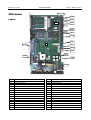
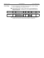
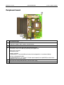
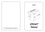
09/01 Rev. 2.13-02
SERVICE MANUAL
TTX 350 – Ocelot
Service / Boards
Handling boards ............................................ 2
CPU board .................................................... 3
Layout ....................................................... 3
Settings ..................................................... 4
Peripheral board............................................ 6
Index ............................................................. 7
Service / Boards, Page 1
09/01 Rev. 2.13-02
SERVICE MANUAL
TTX 350 – Ocelot
Service / Boards, Page 2
Handling boards
ESD protection
All of the (printed circuit) boards detailed below are equipped with, among
other things, large-scale integrated circuits. Voltage surges caused by static
charging from persons or objects can easily destroy the circuits.
Mind the following rules to protect your printer against damages caused by
electrostatic charge.
– When handling boards, make sure that you do not endanger the
electronic circuits by way of static charging or discharging.
– Before opening the printer, place it on a grounded surface.
– Earth your body using an ESD bracelet or other suitable means. If no
suitable ESD protection is available, touch an earthed object, e.g. a
heating radiator, before touching a board.
– Only place boards on earthed surfaces.
Handling
The conducting tracks of state-of-the-art multilayer boards are very thin.
Thus, if the board is bent or warped, the conducting tracks can easily crack.
Avoid bending or warping boards.
Avoid the use of excessive force when removing or inserting boards.
09/01 Rev. 2.13-02
SERVICE MANUAL
TTX 350 – Ocelot
Service / Boards, Page 3
P9
CPU board
P8
CN16
TP1
TP2
Layout
U8
TP3
CN15
CN14
TP4
P7
P5
CN12
TP6
CN11
CN10
CN2
1
CON2
CN17
CN18
CN8
F
TP10
CON1
CN6
CN25
CN24
ID
1
CN2
CN6
CN8
CN10
CN11
CN12
CN14
CN15
CN16
CN17
CN18
CN22
CN24
CN25
P1
Description
Printed circuit board TTX 350, ID No.: A0638-xx
Connection display
Connection voltage cable print head
Connection ventilator
Connection single-start cable
Connection cutter/stacker
Connection ribbon sensor
Connection punch light barrier
Connection reflex light barrier
Connection dispenser light barrier
Connection print-head switch
Connection data-cable print head
Connection motor (Use cable no. 97788)
Connection supply voltage (transformer)
Connection supply voltage (transformer)
CN22
ID
CON1
CON2
P1
P5
P7
P8
P9
TP1
TP2
TP3
TP4
TP6
TP10
U8
F
Description
Serial interface
Parallel interface
Adjustment pot head voltage
Adjustment pot end-of-ribbon light barrier
Adjustment pot punch light barrier
Adjustment pot reflex light barrier
Adjustment pot dispenser light barrier
GND
Test point at P9 dispenser light barrier
Test point at P8 reflex light barrier
Test point at P7 punch light barrier
Test point at P5 end-of-ribbon light barrier
Test point at P1 head voltage
Base for optional real-time clock
Fuse 10AT
09/01 Rev. 2.13-02
SERVICE MANUAL
TTX 350 – Ocelot
Service / Boards, Page 4
Settings
Set sensors as follows:
1. Invoke OTHR/SCHK (sensor check) in the parameter menu.
Sensors
2. Press the CUT or FEED key until the parameter of the sensor to be set
appears in the display (Table: Column "Parameter")
3. Adjust the potentiometer (Table: Column "Pot") until the specified value is
displayed. The display takes place on the printer display for punch/end-ofmaterial photo switch and reflex photo switch.
The setting of the dispenser and the end-of-ribbon photo switch is
performed using the display of a voltmeter at test point TP2 and TP6,
respectively.
The grey cells of the table are used for setting the sensors. The setting is
always made when the photoelectric switch is unblocked. The values with
the photoelectric switch blocked are for checking purposes.
For more details on the parameter OTHR/SCHK, see the section "Info
printouts and parameters".
Sensor
Connector
Setting condition
Pot
Punch/end-of-material
sensor
CN14
without material
(photoelectric switch
unblocked)
with backing material
without material
(photoelectric switch
unblocked); hood closed;
Punch/end-of-material
sensor disconnected
with material
reflex bar
white material
no photoelectric switch
installed
sensor in front of a hole
in the clock disc
(unblocked)
sensor blocked
without material
(photoelectric switch
unblocked)
with material
P7
Reflex sensor
End-of-ribbon sensor
Dispenser sensor
CN15
CN12
CN16
*) approx. 30 higher than without material.
Continued on the next page
Test
point
Setting
value
P8
Parameter
(display)
Pxxx
Value
(display)
12
Rxxx
42*
7
>7
0..9
10..255
0
P5
P9
TP6
TP2
0,2V
0.20 V
Fxx
0
Wxxx
15
0
>50
09/01 Rev. 2.13-02
SERVICE MANUAL
TTX 350 – Ocelot
Service / Boards, Page 5
Set head voltage to the specified voltage using pot P1 (column "Setting
Head voltage
value"). Voltage display via voltmeter at TP10.
From firmware version 1.10 on, or from serial no. 022292 9909-350 on
(digits printed in italics =continuous no.), the setting for both printhead
versions are identical:
Head voltage
CN18
Printhead
P1
TP10
26,0 V
Up to firmware version 1.10, the settings for the printheads are different:
Head voltage
CN18
8,0-Dot Printhead
11,8-Dot Printhead
P1
TP10
26,0 V
23,5 V
Printhead voltage setting only in off-line mode! Setting of the printhead
voltage while the printer is performing a print job is not possible!
09/01 Rev. 2.13-02
SERVICE MANUAL
TTX 350 – Ocelot
Service / Boards, Page 6
Peripheral board
1
CN4
CN6
P1
CN3
ID
1
Description/Function
Peripheral board, ID No.: 99054-xx
Useable for the options cutter, rewinder and cutter/stacker.
P1
Pot P1 infra-red sensor
CN3 Connection infra-red sensor. (three-core cable to the Sub-D plug)
The infra-red sensor is used differently depending on the option used:
Cutting stacker and cutter:
No setting necessary.
Rewinder and infeed:
Set potentiometer P1 so that the difference between the two stop points is at a maximum (display).
Label-present photoelectric switch:
Using potentiometer R41, set a value of 2.5 V (with respect to ground) at test point CN6 (no material in the
photoelectric switch and cover closed).
CN4 Connection main driving motor (four-core cable to the Sub-D plug)
CN6 Test point
09/01 Rev. 2.13-02
SERVICE MANUAL
TTX 350 – Ocelot
Service / Boards, Page 7
Index
R
C
Real-time clock, base .................................3
CPU board ................................................. 3
S
D
Setting, CPU board.....................................4
Setting, head voltage ..................................5
Setting, sensors ..........................................4
Single-start cable, connection.....................3
Display, connection .................................... 3
F
Fuse, base ................................................. 3
L
Layout, CPU board..................................... 3
P
Peripheral board......................................... 6
Printed circuit boards, handling .................. 2
V
Ventilator, connection .................................3