1
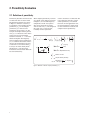
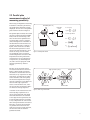
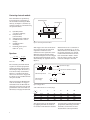
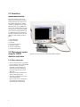
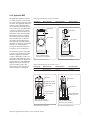
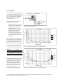
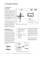
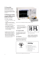
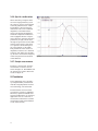
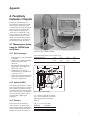
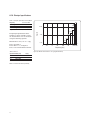
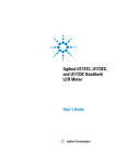
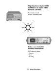
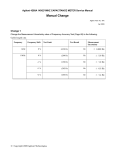
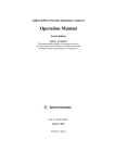
Agilent
Solutions for Measuring Permittivity
and Permeability with LCR Meters and
Impedance Analyzers
Solutions for Measuring Permittivity and Permeability
with LCR Meters and Impedance Analyzers
Application Note 1369-1
1.
2.
Introduction . . . . . . . . . . . . . . . . . . . . . . . . . . . . . . . . . . . . . . . . . . . . . . . . . . . . . . . . . . . . . . . . . . . . . . . . . . . . . . . . . . . . . . . . . . . . . . . 3
Permittivity Evaluation . . . . . . . . . . . . . . . . . . . . . . . . . . . . . . . . . . . . . . . . . . . . . . . . . . . . . . . . . . . . . . . . . . . . . . . . . . . . . . . . . . . . . . 4
2.1. Definition of permittivity. . . . . . . . . . . . . . . . . . . . . . . . . . . . . . . . . . . . . . . . . . . . . . . . . . . . . . . . . . . . . . . . . . . . . . . . . . . . . . . . . . . . . 4
2.2. Parallel plate measurement method . . . . . . . . . . . . . . . . . . . . . . . . . . . . . . . . . . . . . . . . . . . . . . . . . . . . . . . . . . . . . . . . . . . . . . . . . . . 5
2.3. Permittivity measurement system . . . . . . . . . . . . . . . . . . . . . . . . . . . . . . . . . . . . . . . . . . . . . . . . . . . . . . . . . . . . . . . . . . . . . . . . . . . . . 8
2.4. Measurement system using the 16451B dielectric test fixture. . . . . . . . . . . . . . . . . . . . . . . . . . . . . . . . . . . . . . . . . . . . . . . . . . . . . . 8
2.5. Measurement system using the 16453A dielectric test fixture. . . . . . . . . . . . . . . . . . . . . . . . . . . . . . . . . . . . . . . . . . . . . . . . . . . . . 13
3.
Permeability Evaluation . . . . . . . . . . . . . . . . . . . . . . . . . . . . . . . . . . . . . . . . . . . . . . . . . . . . . . . . . . . . . . . . . . . . . . . . . . . . . . . . . . . . 17
3.1. Definition of permeability . . . . . . . . . . . . . . . . . . . . . . . . . . . . . . . . . . . . . . . . . . . . . . . . . . . . . . . . . . . . . . . . . . . . . . . . . . . . . . . . . . . 17
3.2. Inductance measurement method . . . . . . . . . . . . . . . . . . . . . . . . . . . . . . . . . . . . . . . . . . . . . . . . . . . . . . . . . . . . . . . . . . . . . . . . . . . 17
3.3. Permeability measurement system . . . . . . . . . . . . . . . . . . . . . . . . . . . . . . . . . . . . . . . . . . . . . . . . . . . . . . . . . . . . . . . . . . . . . . . . . . . 18
3.4. Measurement system using the 16454A magnetic material test fixture . . . . . . . . . . . . . . . . . . . . . . . . . . . . . . . . . . . . . . . . . . . . . 18
4.
Conclusion. . . . . . . . . . . . . . . . . . . . . . . . . . . . . . . . . . . . . . . . . . . . . . . . . . . . . . . . . . . . . . . . . . . . . . . . . . . . . . . . . . . . . . . . . . . . . . . 20
Appendix . . . . . . . . . . . . . . . . . . . . . . . . . . . . . . . . . . . . . . . . . . . . . . . . . . . . . . . . . . . . . . . . . . . . . . . . . . . . . . . . . . . . . . . . . . . . . . . . . . . . . . .
A.
Permittivity Evaluation of Liquids . . . . . . . . . . . . . . . . . . . . . . . . . . . . . . . . . . . . . . . . . . . . . . . . . . . . . . . . . . . . . . . . . . . . . . . . . . . .
A.1. Measurement system using the 16452A liquid test fixture . . . . . . . . . . . . . . . . . . . . . . . . . . . . . . . . . . . . . . . . . . . . . . . . . . . . . . .
A.1.1. Main advantages . . . . . . . . . . . . . . . . . . . . . . . . . . . . . . . . . . . . . . . . . . . . . . . . . . . . . . . . . . . . . . . . . . . . . . . . . . . . . . . . . . . .
A.1.2. Applicable MUT . . . . . . . . . . . . . . . . . . . . . . . . . . . . . . . . . . . . . . . . . . . . . . . . . . . . . . . . . . . . . . . . . . . . . . . . . . . . . . . . . . . . .
A.1.3. Structure . . . . . . . . . . . . . . . . . . . . . . . . . . . . . . . . . . . . . . . . . . . . . . . . . . . . . . . . . . . . . . . . . . . . . . . . . . . . . . . . . . . . . . . . . . .
A.1.4. Principal specifications . . . . . . . . . . . . . . . . . . . . . . . . . . . . . . . . . . . . . . . . . . . . . . . . . . . . . . . . . . . . . . . . . . . . . . . . . . . . . . .
A.1.5. Operation method. . . . . . . . . . . . . . . . . . . . . . . . . . . . . . . . . . . . . . . . . . . . . . . . . . . . . . . . . . . . . . . . . . . . . . . . . . . . . . . . . . . .
A.1.6. Special considerations. . . . . . . . . . . . . . . . . . . . . . . . . . . . . . . . . . . . . . . . . . . . . . . . . . . . . . . . . . . . . . . . . . . . . . . . . . . . . . . .
21
21
21
21
21
21
22
23
23
References . . . . . . . . . . . . . . . . . . . . . . . . . . . . . . . . . . . . . . . . . . . . . . . . . . . . . . . . . . . . . . . . . . . . . . . . . . . . . . . . . . . . . . . . . . . . . . . . . . . . . 24
2
1. Introduction
Recently,electronicequipment
technology has dramatically evolved
to the point where an electronic
component’s material characteristics
becomes a key factor in a circuit’s
behavior. For example, in the manufacture of high capacitance multilayer ceramic capacitors (MLCCs),
which are being used more in digital
(media) appliances, employing high
κ (dielectric constant) material
isrequired.Inaddition,various
electrical performance evaluations,
suchasfrequencyandtemperature
response, must be performed before
the materials are selected.
Infieldsoutsideofelectronic
equipment,evaluatingtheelectrical
characteristics of materials has
become increasingly popular. This is
because composition and chemical
variations of materials such as solids
andliquidscanadoptelectrical characteristic responses as substituting
performance parameters.
A material evaluation measurement
system is comprised of three main
pieces. These elements include:
precise measurement instruments,
test fixtures that hold the material
under test, and software that can
calculate and display basic material
parameters, such as permittivity and
permeability. Various measurement
methods for permittivity and permeability currently exist (see Table 1).
However, this note’s primary focus
will be on methods that employ
impedance measurement technology,
which have the following advantages:
•Widefrequencyrangefrom20Hz
to1GHz
•Highmeasurementaccuracy
•Simplepreparations(fabrication
of material, measurement setup)
for measurement
This note begins by describing
measurement methods, systems,
and solutions for permittivity in
Section2,followedbypermeability
inSection3.Theresistivitymeasurement system and the permittivity
measurementsystemforliquidsare
described later in the appendix.
Table 1. Measurement technology and methods for permittivity and permeability parameters
Measurement parameter
Measurement technology
Impedance analysis
Network analysis
Permittivity
Permeability
Impedance analysis
Network analysis
Measurement method
Parallel plate
Reflection wave
S parameters
Cavity
Free space
Inductance
Reflection wave
S parameters
Cavity
3
2. Permittivity Evaluation
2.1. Definition of permittivity
Permittivity describes the interaction
of a material with an electric field.
Theprincipalequationsareshown
in Figure 1. Dielectric constant (κ)
isequivalenttothecomplexrelative
permittivity (εr*) or the complex
permittivity (ε*) relative to the
permittivity of free space (ε0). The
real part of complex relative permittivity (εr´) is a measure of how much
energy from an external field is
stored in a material; εr´ > 1 for most
solidsandliquids.Theimaginary
part of complex relative permittivity
(εr´´) is called the loss factor and is a
measure of how dissipative or lossy
a material is to an external field. εr´´
isalways>0andisusuallymuch
smaller than εr´. The loss factor
includes the effects of both dielectric
loss and conductivity.
Whencomplexpermittivityisdrawn
as a simple vector diagram as shown
in Figure 1, the real and imaginary
componentsare90°outofphase.
The vector sum forms an angle δ
with the real axis (εr´). The tangent of
this angle, tan δ or loss tangent,
is usually used to express the
κ* =
relative “lossiness” of a material. The
term “dielectric constant” is often
called “permittivity” in technical
literature.Inthisapplicationnote,
the term permittivity will be used
to refer to dielectric constant and
complex relative permittivity.
*
ε*r = εε0 = ε'r - j ε"r =
(Real part)
ε*r
ε"r
δ
ε'r
(Imaginary part)
ε' - j
ε0
ε"
ε0
εr" (Imaginary)
tan δ = ε ' (Real)
r
tan δ = D (Dissibation factor)
κ* = Dielectic constant
ε*r = Complex relative permitivity
of
1
-9 [F/m]
ε0 = Permitivity
free space 36π X 10
Figure 1. Definition of relative complex permittivity (εr*)
4
2.2. Parallel plate
measurement method of
measuring permittivity
Whenusinganimpedance-measuring
instrument to measure permittivity,
the parallel plate method is usually
employed. An overview of the parallel
platemethodisshowninFigure2.
The parallel plate method, also called
thethreeterminalmethodinASTM
D150,involvessandwichingathin
sheetofmaterialorliquidbetween
two electrodes to form a capacitor.
(Note: Throughout the remainder of
this document materials under test,
whether the material is a solid or a
liquid,willbereferredtoasMUT.)
The measured capacitance is then
usedtocalculatepermittivity.Inan
actual test setup, two electrodes
are configured with a test fixture
sandwiching dielectric material. The
impedance-measuring instrument
would measure vector components
of capacitance (C) and dissipation
(D) and a software program would
calculate permittivity and loss
tangent.
The flow of the electrical field in
an actual measurement is shown in
Figure3.Whensimplymeasuring
the dielectric material between two
electrodes, stray capacitance or edge
capacitance is formed on the edges
oftheelectrodesandconsequently
the measured capacitance is larger
than the capacitance of the dielectric
material. The edge capacitance
causes a measurement error, since
the current flows through the dielectric material and edge capacitor.
Electrodes (Area = A)
Equivalent
circuit
Y = G + jωCp
= jωCo
Cp
G
Co : Air capacitance
G
(CpCo – j ωCo
)
εr' = ( At ** Cp
εo)
εr" = (ω * Rpt* A * ε )
o
εr*
Solid
thickness = t
G
(CpCo – jωCo
)
Liquid
=
Figure 2. Parallel plate method
Guard electrodes
Edge capacitance (stray)
-
+
Electrical field
-
+
Electrical field
Figure 3. Effect of guard electrode
A solution to the measurement error
caused by edge capacitance is to
use the guard electrode. The guard
electrode absorbs the electric field
at the edge and the capacitance that
is measured between the electrodes
is only composed of the current that
flows through the dielectric material.
Therefore, accurate measurements
arepossible.Whenthemainelectrode is used with a guard electrode,
the main electrode is called the
guarded electrode.
5
Contacting electrode method:
This method derives permittivity
by measuring the capacitance of
theelectrodescontactingtheMUT
directly (see Figure 4). Permittivity
and loss tangent are calculated using
theequationsbelow:
Cp:
D:
tm:
A:
d:
ε0:
Equivalent parallel
capacitance of MUT [F]
Dissipation factor
(measured value)
Average thickness of MUT [m]
Guarded electrode’s surface
area[m2]
Guarded electrode’s
diameter[m]
Permittivity of free space =
8.854 x 10⁻¹² [F/m]
Equations:
εr =
tm x Cp
tm x Cp
=
2
A x ε0
π d2 x ε 0
tan δ = D
The contacting electrode method
requiresnomaterialpreparation
and the operation involved when
measuring is simple. Therefore, it
is the most widely used method.
However, a significant measurement error can occur if airgap and
its effects are not considered when
using this method.
WhencontactingtheMUTdirectly
with the electrodes, an airgap is
formedbetweentheMUTandthe
electrodes. No matter how flat and
parallelbothsidesoftheMUTare
fabricated, an airgap will still form.
Guarded electrode
Guard electrode
d
g
tm
MUT
Unguarded electrode
Figure 4. Contacting electrode method
This airgap is the cause for measurement error because the measured
capacitance will be the series
connection of the capacitance of the
dielectric material and the airgap.
The relationship between the airgap’s
thickness and measurement error is
determinedbytheequationshownin
Figure 5.
A
Co = εo t Capacitance of airgap
a
A
Capacitance of dielectric material
Cx = εx εo
tm
ta
tm
Cerr =
Measured capacitance
Measured error
due to airgap
1-
εerr
εx
1
=
1
1
+
Co
Cx
=
εerr εo t
A
m + ta
εx - 1
t
εx + tma
Figure 5. Airgap effects
Table 2. Measurement error caused by airgap
ta /tm
0.001
0.005
0.01
0.05
0.1
εr’
2
5
10
20
50
100
0.1%
0.5%
1%
5%
8%
0.4%
2%
4%
16%
27%
1%
4%
8%
30%
45%
2%
9%
16%
48%
63%
5%
20%
33%
70%
82%
9%
33%
50%
83%
90%
This airgap effect can be eliminated,
by applying thin film electrodes to
the surfaces of the dielectric material.
6
Measurement error is a function of
the relative permittivity (εr´) of the
MUT,thicknessoftheMUT(tm), and
the airgap’s thickness (ta).Sample
results of measurement error have
beencalculatedinTable2.Notice
that the effect is greater with thin
materials and high κ materials.
Anextrastepisrequiredformaterial
preparation (fabricating a thin film
electrode), but the most accurate
measurements can be performed.
Non-contacting electrode
method
Thismethodwasconceptualized
to incorporate the advantages and
exclude the disadvantages of the
contactingelectrodemethod.It
doesnotrequirethinfilmelectrodes,
but still solves the airgap effect.
Permittivity is derived by using the
results of two capacitance measurementsobtainedwiththeMUTand
without it (Figure 6).
Cs1: Capacitance without MUT
inserted[F]
Cs2: Capacitance with MUT inserted[F]
D1: Dissipation factor without MUT
inserted
D2: Dissipation factor with MUT inserted
tg : Gap between guarded/guard
electrode and unguarded electrode [m]
tm: Average thickness of MUT [m]
Theoretically, the electrode gap (tg)
should be a little bit larger than the
thicknessoftheMUT(tm).Inother
words, the airgap (tg – tm) should be
extremely small when compared to
thethicknessoftheMUT(tm). These
requirementsarenecessaryforthe
measurement to be performed
appropriately. Two capacitance
measurements are necessary, and
the results are used to calculate
permittivity.Theequationisshown
at right.
Equations:
'
εr =
1
t
C
1− 1− s1 x g
Cs2 tm
tan δ = D2 + εr ' x (D2 − D1) x
tg
−1 (when tan δ <<1)
tm
Guarded electrode
Guard electrode
g
d
MUT
tg
tm
Unguarded electrode
Figure 6. Non-contacting electrode method
Table 3. Comparison of parallel plate measurement methods
Method
Contacting electrode
(without thin film electrode)
Non-contacting electrode
Contacting electrode
(with thin film electrode)
Accuracy
LOW
MEDIUM
HIGH
Application MUT
Solid material with a flat and
smooth surface
Solid material with a flat and
smooth surface
Thin film electrode must be
applied onto surfaces
Operation
1 measurement
2 measurements
1 measurement
7
2.3. Permittivity
measurement system
Two measurement systems that
employ the parallel plate method
will be discussed here. The first is
the 16451B dielectric test fixture,
which has capabilities to measure
solidmaterialsupto30MHz.The
latteristhe16453Adielectricmaterial test fixture, which has capabilities to measure solid materials up
to1GHz.Detailsofmeasurement
systems described in this note will
follow the subheadings outlined
below:
1)
2)
3)
4)
5)
6)
7)
Main advantages
Applicable MUT
Structure
Principal specifications
Operation method
Special considerations
Sample measurements
2.4. Measurement system
using the 16451B
dielectric test fixture
2.4.1. Main advantages
•Precisemeasurementsarepossible
inthefrequencyrangeupto30MHz
•Fourelectrodes(AtoD)are
provided to accommodate the
contacting and non-contacting
electrode methods and various
MUTsizes
•Guardelectrodetoeliminatethe
effect of edge capacitance
•Attachmentsimplifiesopenand
short compensation
•Canbeusedwithanyimpedancemeasuring instrument with a
4-terminal pair configuration
8
Applicable measurement instruments: E4990A, 4285A, E4980A, and E4981A
2.4.2. Applicable MUT
The applicable dielectric material
is a solid sheet that is smooth and
hasequalthicknessfromoneendto
the other. The applicable dielectric
material’ssizeisdeterminedby
the measurement method and type
of electrode to be used. Electrodes
A and B are used for the contacting electrode method without the
fabrication of thin film electrodes.
Electrodes C and D are used for
the contacting electrode method
with the fabrication of thin film
electrodes.Whenemployingthe
non-contacting electrode method,
electrodesAandBareused.Inthis
method, it is recommended to
process the dielectric material to
a thickness of a few millimeters.
The difference between electrodes
A and B is the diameter (the same
difference applies to electrodes
C and D). Electrodes A and C are
adaptedforlargeMUTsizes,and
electrodes B and D are adapted for
smallerMUTsizes.Theapplicable
MUTsizesforeachelectrodeare
shown in Tables 4 and 5. The
dimensions of each electrode are
showninFigures7through10.
Table 4. Applicable MUT sizes for electrodes A and B
Electrode type
A
B
Material diameter
40 mm to 56 mm
10 mm to 56 mm
Material thickness
t ≤ 10 mm
t ≤ 10 mm
Electrode diameter
38 mm
5 mm
Electrode-A
Electrode-B
∅38
0.2
∅5
0.13
∅56
∅20
Test material
Test material
≤ 10
≤ 10
40 to 56
10 to 56
Note: ∅ signifies diameter.
Dimensions are in millimeters.
Note: ∅ signifies diameter.
Dimensions are in millimeters.
Figure 7. Electrode A dimensions
Figure 8. Electrode B dimensions
Table 5. Applicable MUT sizes for electrodes C and D
Electrode type
C
D
Material diameter
56 mm
20 mm to 56 mm
Material thickness
t ≤ 10 mm
t ≤ 10 mm
Electrode diameter*
5 to 50 mm
5 to 14 mm
∅7
∅7
Electrode-C
Electrode-D
∅52
∅56
Guard thin film electrode
∅16
∅20
Guarded thin film electrode
Test material
Test material
5 to 50
≤ 52
The gap width shall be
as small as practical
5 to 14
≤ 16
The gap width shall be
as small as practical
≤ 10
56
Note: ∅ signifies diameter.
Dimensions are in millimeters.
Figure 9. Electrode C dimensions
≤ 10
20 to 50
Note: ∅ signifies diameter.
Dimensions are in millimeters.
Figure 10. Electrode D dimensions
*Diameter of applied thin film electrodes on surfaces of dielectric material
9
2.4.3. Structure
Inordertoeliminatethemeasurement
error caused by edge capacitance, a
three-terminal configuration (including a guard terminal) is employed.
The structure of the 16451B is
shown in Figure 11.
Guard terminal
Unguarded electrode
Guarded electrode
Hcur
Hpot
Lput
Lcur
The electrodes in the 16451B are
made up of the following:
The guard electrode encompasses
the guarded (or main) electrode and
absorbs the electric field at the edge
of the electrodes, making accurate
permittivity measurements possible.
Figure 11. Structure of the 16451B
Δ ε r' / ε r' [%]
1. Unguardedelectrode,whichis
connected to the measurement
instrument’s high terminal.
2. Guardedelectrode,whichis
connected to the measurement
instrument’s low terminal.
3. Guardelectrode,whichis
connected to the measurement
instrument’s guard terminal
(the outer conductor of the BNC
connectors).
4-terminal
pair
Electrode A:
50
45
40
35
30
25
20
15
10
5
0
t = 1 [mm]
er = 50
er = 20
er = 10
er = 5
er = 2
40 100
1k
10 k
100 k
1M
10 M 30 M
Frequency [Hz]
2.4.4. Principal specifications
Figure 12. Permittivity measurement accuracy (supplemental data)
Table 6. Principal specifications of the 16451B
≤ 30 MHz
±42 V
0 °C to 55 °C
4-terminal pair, BNC
1m
Open/short*
The principal specifications are shown
inTable6.Figures12and13show
the measurement accuracy when
Agilent’sE4990Aisused.Further
details about the measurement
accuracy can be obtained from the
Accessories Selection Guide for
Impedance Measurements
(literaturenumber5965-4792E)
Electrode A:
10
tan δ error (Ea)
Frequency
Max voltage
Operation temperature
Terminal configuration
Cable length
Compensation
t = 1 [mm]
1
er = 50
er = 20
er = 10
er = 5
er = 2
0.1
0.01
0.001
40 100
1k
10 k
100 k
1M
10 M 30 M
Frequency [Hz]
Figure 13. Loss tangent measurement accuracy (supplemental data)
*When using the 4285A or E4990A above 5 MHz, it is necessary to perform load compensation in addition to open and short compensation.
For more details, please refer to Section 2.4.5 Operation method.
10
2.4.5. Operation method
Figure 14 displays the flowchart
when using the 16451B for permittivity measurements. Each step in
the flowchart is described here:
Step 1. Prepare the dielectric material:
FabricatetheMUTtotheappropriate
size.UseFigures7through10as
references.Ifthecontactingelectrode
method with thin film electrodes is
employed, apply thin film electrodes
tothesurfacesoftheMUT.
Step 2. Attach the guarded electrode:
Selecttheappropriateelectrodeand
fit it into the 16451B.
Step 3. Connect the 16451B: Connect
the 16451B to the unknown terminals of the measurement instrument.
Step 4. Cable length compensation:
Setthemeasurementinstrument’s
cable length compensation function
to 1 m. Refer to the measurement
instrument’s operation manual for
the setting procedure.
Step 5. Compensate the residual
impedanceofthe16451B:Usethe
furnished attachment to perform
open and short compensation at a
specifiedfrequency.Thisisnecessary
before adjusting the guarded and
unguarded electrodes to be parallel
to each other.
Step 6. Adjust the electrodes: To
enhance the measurement performance, a mechanism is provided to
adjust the guarded and unguarded
electrodes to be parallel to each other.
By performing this adjustment, the
occurrence of the airgap when using
the contacting electrode method is
minimizedandanairgapwithuniform
thickness is created when using the
non-contacting electrode method. The
adjustment procedure is discussed in
the operation manual of the 16451B.
Step 8. Compensate the residual
impedanceofthe16451B:Usethe
furnished attachment to perform
open and short compensation of
the measurement conditions set in
Step7.
WhenusingtheAgilent4285Aor
E4990Aabove5MHz,itisnecessary
to perform load compensation also.
Thisisbecauseforhighfrequency
measurements, it is difficult to
disregard the residual impedance,
which cannot be removed by open
and short compensation.
Inordertocompensatethefrequency
response of the 16451B, a measured
valueat100kHzisusedasastandard
value and load compensation is
performedathighfrequencies.The
air capacitance formed by creating
an airgap between the electrodes
(with nothing inserted) is adopted
as the load device for the 16451B.
Table 7 lists the recommended
capacitance values that are obtained
by adjusting the height of the airgapbetweentheelectrodes.Itis
assumed that the air capacitance
hasnofrequencydependency,no
loss and has a flat response. The
capacitancevalue(Cp)at100kHz
(Gisassumedtobezero)isused
for load compensation.
Step 9.InsertMUT:InserttheMUT
between the electrodes.
Step 10. Cp-D measurement: The
capacitance (Cp) and dissipation factor(D)ismeasured.Whenemploying
the non-contacting electrode method,
two Cp-D measurements are performed,withandwithouttheMUT.
Step 11. Calculate permittivity: As
previouslydiscussedinSection2.2,
usetheappropriateequationto
calculate permittivity.
START
1. Prepare the dielectric material
2. Attach the guarded electrode
3. Connect the 16451B
4. Cable length compensation
5. Compensation for adjustment
of electrodes
6. Adjust the electrodes
7. Set the measurement conditions
8. Compensate the residual impedance
9. Insert the MUT
10. Cp-D measurement
11. Calculate permittivity
END
Figure 14. Measurement procedure flowchart
for the 16451B
Table 7. Load values
Electrode
A
B
C, D
Recommended capacitance*
50 pF ± 0.5 pF
5 pF ± 0.05 pF
1.5 pF ± 0.05 pF
* Measured Cp value at 100 kHz
Step 7.Setthemeasurementconditions: Measurement conditions such
asfrequencyandtestvoltagelevel
are set on the measurement instrument. Refer to the measurement
instrument’s operation manual for
the setting procedure.
11
2.4.6 Special considerations
As mentioned before, to reduce the
effect of the airgap, which occurs
betweentheMUTandtheelectrodes,
it is practical to employ the contacting
electrode method with thin film
electrodes(RefertoSection2.2).
Electrodes C and D are provided with
the 16451B to carry out this method.
Materials under test that transform
under applied pressure cannot keep
afixedthickness.ThistypeofMUT
is not suitable for the contacting
electrodemethod.Instead,the
non-contacting method should be
employed.
Whenthenon-contactingmethod
is employed, the electrode gap tg is
requiredtobeatmost10%larger
thanthethicknessoftheMUT.Itis
extremelydifficulttocreatea10%
electrode gap with thin film materials.
Therefore, it is recommended that
only materials thicker than a few
millimeters be used with this method.
The micrometer on the 16451B is
designed to make a precise gap when
using the non-contacting electrode
method. Accurate measurements of
thethicknessofMUTcannotbemade,
when employing the contacting electrode method. This is because the
micrometer scale is very dependent
upon the guard and the unguarded
electrodesbeingparallel.Usinga
separate micrometer for measuring
thickness is recommended.
12
2.5. Measurement system
using the 16453A dielectric
material test fixture
2.5.1. Main advantages
• Widefrequencyrangefrom
1MHz–1GHz
• OptionE4991B-002(material
measurement software) internal
firmware in the E4991B solves
edge capacitance effect
• Open,shortandloadcompensation
• Directreadoutsofcomplex
permittivity are possible with
theOptionE4991B-002(material
measurement software) internal
firmware in the E4991B.
• Temperaturecharacteristics measurements are possible
from–55°Cto+150°C(with
OptionsE4991B-002and
E4991B-007).
* For temperature-response evaluation, Option
E4991B-007 temperature characteristic test
kit is required. A Microsoft Excel VBA
sample program is pre-installed in the
E4991B that provides chamber control and
measurement setup functions.
The sample program can be copied to an
external PC.
Applicable measurement instruments: E4991B (Option E4991B-002)*
2.5.2. Applicable MUT
d
The applicable dielectric material is
a solid sheet that is smooth and has
equalthicknessfromoneendtothe
other.TheapplicableMUTsizeis
shown in Figure 15.
t
2.5.3. Structure
Thestructureofthe16453Acanbe
viewed in Figure 16. The upper electrode has an internal spring, which
allowstheMUTtobefastened
between the electrodes. Applied
pressure can be adjusted as well.
The16453Aisnotequippedwith
a guard electrode like the 16451B.
This is because a guard electrode at
highfrequencyonlycausesgreater
residual impedance and poor frequencycharacteristics.Tolessen
the effect of edge capacitance, a
correction function based on simulation results is used in the E4991B,
OptionE4991B-002(material
measurement) firmware.
Also, residual impedance, which is a
major cause for measurement error,
cannot be entirely removed by open
and short compensation. This is
why PTFE is provided as a load
compensation device.
t
d ≥ 15 mm
0.3 mm ≤ t ≤ 3 mm
Figure 15. Applicable MUT size
Upper electrode
spring
Diameter
is 10 mm
MUT
16453A
Diameter
is 7 mm
Lower electrode
Figure 16. Structure of the 16453A
13
2.5.4. Principal specifications
Table 8. Principal specifications of the 16453A
Frequency
Max. voltage
Operating temperature
Terminal configuration
Compensation
1 MHz to 1 GHz
±42 V
-55 °C to +150 °C*
7 mm
Open, short and load
* Must be accompanied by the E4991B
with Options E4991B-002 and E4991B-007.
The principal specifications are shown
inTable8.Figures17and18show
the measurement accuracy when
the E4991B is used. Further details
about the measurement accuracy
can be obtained from the operation
manual supplied with the instrument.
Figure 17. Permittivity measurement accuracy (supplemental data)
2.5.5. Operation method
Figure 19 displays the flowchart
whenusingthe16453AandE4991B
for permittivity measurements. The
steps in the flowchart are described
here. For further details, please
refer to the Quick Start Guide for
the E4991B.
START
1. Select the measurement mode
Figure 18. Loss tangent measurement accuracy (supplemental data)
2. Input thickness of MUT
3. Set the measurement conditions
Step 1.Selectthemeasurement
mode:Selectpermittivitymeasurement in E4991B’s utility menu.
4. Connect the 16453A
5. Input thickness of load device
Step 2.InputthethicknessofMUT:
EnterthethicknessoftheMUTinto
theE4991B.Useamicrometerto
measure the thickness.
Step 5.Inputthethicknessofload
device: Before compensation, enter
the furnished load device’s (PTFE
board) thickness into the E4991B
Step 6. Calibrate the measurement
plane: Perform open, short, and load
calibration.
6. Calibrate the measurement plane
7. Insert the MUT
8. Measure the MUT
END
Figure 19. Measurement procedure flowchart
for the 16453A
14
Step 3.Setthemeasurementconditions of the E4991B: Measurement
conditionssuchasfrequency,test
voltage level, and measurement
parameter are set on the measurement
instrument.
Step 4.Connectthe16453A:Connect
the16453Atothe7mmterminalof
the E4991B.
Step 7.InsertMUT:InserttheMUT
between the electrodes.
Step 8.MeasuretheMUT:Themeasurement result will appear on the
display.Thedatacanbeanalyzed
using the marker functions.
2.5.6 Special considerations
As with the previous measurement
system, an airgap, which is formed
betweentheMUTandtheelectrodes,
can be a primary cause of measurement error. Thin materials and high k
materials are most prone to this
effect. Materials with rough surfaces
(Figure20)canbesimilarlyaffected
by airgap.
t2
t1
t 2 > t1
Cut-out for the positioning of the thin film electrode.
φ7
Electrode
Back
Dielectric
material
φ 10
Electrode
Airgap
Front
φ2
Electrode
24.5
13
MUT
6
9.9
25.1
25.1
9.9
70
Electrode
Unit: mm
Figure 21. Fabricated thin film electrode’s size
Figure 20. Rough-surfaced dielectric material
Thereisatechniquetoapplya
thin film electrode onto the surfaces
of the dielectric material in order to
eliminate the airgap that occurs
betweentheMUTandtheelectrodes.
ThistechniqueisshowninFigure21
and22Anelectrodetheexactshape
andsizetofitthe16453Aisfabricated
onto the dielectric material using
either high-conductivity silver pastes
orfired-onsilver.TheMUTshould
beshapedasinFigure21,withthe
thin film electrode thinner than the
dielectricmaterial.Inthiscase,itis
vital to appropriately position the
fabricated thin film electrode onto
theMUT,topreciselycontactthe
electrodesofthe16453A(Figure22).
Following this process will ensure
a more accurate and reliable
measurement.
Inaddition,iftheMUTsareverythin,
forexamplecloseto100 µm, it is
possibletostack3or4otherMUTs
and then make the measurement.
This will reduce the airgap and
increase measurement precision.
TheMUTmustbesmoothandnot
transform under applied pressure.
Figure 22. Positioning of the fabricated thin film on the MUT
Another point to consider is the
adjusting mechanism of the upper
electrode’s spring pressure. The
spring’s pressure should be as
strong as possible in order to
minimizetheoccurrenceofthe
airgapbetweentheMUTandthe
electrodes. However, MUTswhich
transform under extreme pressure,
cannot be measured correctly, since
the thickness is affected. To achieve
stable measurements, the spring
pressure should be set at a level that
doesnottransformtheMUT.
15
2.5.7. Sample measurements
AsshowninFigure23,ameasurementresultforglassepoxyfrequency
characteristic can be obtained by
usingtheE4991Bwiththe16453A.
Figure 23. Frequency response of glass epoxy (εr = 4.5)
16
3. Permeability Evaluation
3.1. Definition of
permeability
Permeability describes the interaction
of a material with a magnetic field.
Itistheratioofinduction,B,tothe
appliedmagnetizingfield,H.Complex
relative permeability (µr*) consists
of the real part (µr’) that represents
the energy storage term and the
imaginary part (µr”) that represents
thepowerdissipationterm.Itisalso
the complex permeability (µ*) relative
to the permeability of free space (µ0)
asshowninFigure24.
The inefficiency of magnetic material
is expressed using the loss tangent,
tan δ. The tan δ is the ratio of (µr”)
to (µr’). The term “complex relative
permeability” is simply called “permeability” in technical literature.
Inthisapplicationnote,theterm
permeability will be used to refer
to complex relative permeability.
3.2. Inductance
measurement method
Relative permeability of magnetic
material derived from the self-inductance of a cored inductor that has a
closed loop (such as the toroidal core)
is often called effective permeability.
The conventional method of measuring effective permeability is to wind
some wire around the core and
evaluate the inductance with respect
to the ends of the wire. This type of
measurement is usually performed
with an impedance measuring
instrument. Effective permeability
is derived from the inductance measurement result using the following
equations:
'
μe =
"
μe =
μ*
μ* r =
μ0
= μ'r -
j μ "r =
(real part)
(imaginary part)
μ'
-j
μ0
B
μ*r
μ" r
δ
μ'r
H
tan δ =
μ* =
μ"
μ0
μr"
(imaginary)
μr'
(real)
μ*r = Complex relative permeability
B
H
μ0 = Permeability of
free space
4π X 10-7 [H/m]
Figure 24. Definition of complex permeability (m*)
Reff:
Leff:
Rw:
Lw:
N:
:
A:
ω:
µ0:
Depending on the applied magnetic
field and where the measurement
is located on the hysteresis curve,
permeability can be classified in
degree categories such as initial or
maximum.Initialpermeabilityis
the most commonly used parameter
among manufacturers because most
industrial applications involving
magnetic material use low power
levels.*
Equivalent resistance of magnetic
core loss including wire resistance
Inductance of toroidal coil
Resistance of wire only
Inductance of air-core coil
inductance
Turns
Average magnetic path length of
toroidal core [m]
Cross-sectional area of toroidal
core [m2]
2π f (frequency)
4π x 10-7 [H/m]
This application note focuses on
effective permeability and initial
permeability, derived from the
inductance measurement method.
Equivalent
circuit
Lw
Rw
Leff
Reff
L eff
μ0 N 2 A
( Reff – Rw )
μ0 N 2 ω A
Figure 25. Method of measuring effective permeability
* Some manufacturers use initial permeability even for magnetic materials that are employed at high power levels.
17
3.3. Permeability
measurement system
The next section demonstrates a
permeability measurement system
using the 16454A magnetic material
test fixture.
3.4. Measurement system
using the 16454A magnetic
material test fixture
3.4.1. Main advantages
• Widefrequencyrangefrom1kHz
to1GHz
• Simplemeasurementswithout needing a wire wound around the
toroid
• Twofixtureassembliesare
providedfordifferentMUTsizes
• Directreadoutsofcomplex
permeability are possible with
theE4991B(OptionE4991B-002
material measurement software)
orwiththeE4990A.
Applicable instruments: E4991B (Option E4991B-002)*, E4990A, and 42942A
• Temperaturecharacteristic
measurements are possible from
–55°Cto+150°C(withthe
E4991BOptionsE4991B-002and
E4991B-007)
≤ 8 mm
≤ 20 mm
≥ 3.1 mm
≥ 5 mm
≤ 8.5 mm
≤ 3 mm
3.4.2. Applicable MUT
Small size
* For temperature-response evaluation, Option
E4991B-007 temperature characteristic test
kit is required. A Microsoft Excel VBA sample
program is pre-installed in the E4991B that
provides chamber control and measurement
setup functions. The sample program can be
copied to an external PC. The E4990A does not
have a high temperature test head.
The applicable magnetic material
can only be a toroidal core. The
applicableMUTsizeisshownin
Figure26.
Large size
Figure 26. Applicable MUT size
single-turn inductor, with no flux
leakage, is formed. Permeability is
derived from the inductance of the
toroidal core with the fixture.
3.4.3. Structure
The structure of the 16454A and the
measurement concept are shown in
Figure27.Whenatoroidalcoreis
inserted into the 16454A, an ideal,
•
•
µ=
c
c
+1
b
b
•
µ
•
E4991B/E4990A
Relative permeability
Zm
Measured impedance with toroidal core
Zsm
Measured impedance without toroidal core
•
µ0
Permeability of free space
h
c
b
Height of MUT (material under test)
Outer diameter of MUT
Inner diameter of MUT
Figure 27. Structure of the 16454A and measurement concept
18
•
(Zm− Zsm) 2π
jωµ0 h ln
3.4.4. Principal specifications
5%
h In
3000
Table 9. Principal specifications of the 16454A
2500
1 kHz to 1 GHz
±500 mA
-55 °C to +150 °C
7 mm
Short
2000
μr'
Frequency
Max dc bias current
Operating temperature
Terminal configuration
Compensation
Step 2. Connect the 16454A: Connect
10%
1000
500
20%
20%
0
1k
10k
100k
1M
10M
Frequency [Hz]
10M 1G
Figure 28. Permeability measurement accuracy (supplemental data)
Figure30displaystheflowchartwhen
using the 16454A for permeability
measurements. Each step of the
flowchart is described here:
h In
1.00 E+01
C
= 10 [mm]
b
1.00 E+00
tan δ error (Ea)
Step 1. Calibrate the measurement
instrument:WhenusingtheE4991B,
calibrate at the 7 mm terminal.
WhenusingtheE4990A,perform
SETUPonthe7mmterminal of the
42942A.
2500
10%
Principal specifications of the
16454A are shown in Table 9 above.
Figures28and29showthemeasurement accuracy when either the
E4991BortheE4990Aareused.
3.4.5. Operation method
C
= 10 [mm]
b
μ'r =300
.00 E+00
μ'r =100
μ'r =1000
μ'r =3
μ'r =10
.00 E+00
μ'r =3000
.00 E+00
1k
μ'r =30
10k
100k
1M
10M
Frequency [Hz]
100M
the 16454A to the measurement
instrument’s7mmterminal.When
using the E4991B, select the permeability measurement mode.
Figure 29. Loss tangent measurement accuracy (supplemental data)
Step 3. Compensate the residual
Step 7.MeasuretheMUT:The
measurement result will appear on
thedisplay.Thedatacanbeanalyzed
using the marker functions.
impedanceofthe16454A:Insert
onlytheMUTholderandperform
short compensation.
Step 4.InputsizeofMUT:Enterthe
sizeoftheMUTintothemeasurement
instrument’smenu.Useamicrometer
tomeasurethesize.
Step 5.InsertMUT:InserttheMUT
with the holder into the 16454A.
Step 6.Setthemeasurementconditions: Measurement conditions such
asfrequency,testsignallevel,and
measurement parameter are set on
the measurement instrument.
Internalfirmwarecomesstandard
with the material measurement function when using the E4991B (Option
E4991B-002).Formore details,
refer to the Operation Manual of
the E4991B.
1G
START
1. Calibrate the instrument
2. Connect the 16454A
3. Compensate the residual impedance
4. Input the size of the MUT
5. Insert the MUT
6. Set the measurement conditions
7. Measure the MUT
END
Figure 30. Measurement procedure flowchart
for the 16454A
19
3.4.6. Special considerations
Whenmeasuringamagneticmaterial with a high permittivity (near
10orabove),precisemeasurements
cannotbeperformednear1GHz.
Permeability is derived from the
inductance value of the combined
impedanceoftheMUTandthe
fixture. The measured impedance
should be composed of inductance
and a negligible amount of capacitance.Whenthemagneticmaterial’s
permittivity is high, current flows
throughthespacebetweentheMUT
andthefixture.Thisisequivalent
to a capacitor connected in paralleltotheinductor(oftheMUT).
This parallel LC circuit causes an
impedance-resonance at a destined
frequency.Thehigherthepermittivity,thelowertheresonantfrequency
will be and precise measurements
will be difficult.
3.4.7. Sample measurements
Frequencycharacteristicmeasurement results of a ferrite core are
showninFigure31.TheE4991Band
the 16454A were used to obtain the
resultsinFigure31.
4. Conclusion
Inthisapplicationnote,permittivity and permeability measurement
methods using impedance measurement technology were discussed.
The discussions covered various
test fixtures’ structures, applicable
MUTsizes,operationmethodsand
special considerations. By using this
application note as a reference, a
measurement solution that satisfies
measurement needs and conditions
can be selected easily.
20
Figure 31. Frequency response of ferrite core (µr = 120)
Appendix
A. Permittivity
Evaluation of Liquids
be washed. Nickel is used for the
electrodes,spacers,liquidinletand
outlet and fluoro-rubber is used for
theO-rings.
Permittivity measurements are
oftenusedforevaluationofliquid
characteristics. Permittivity measurementsdonotchangetheliquid
physically and can be conducted
rathersimplyandquickly.Asa
result,theyareutilizedinawide
array of research areas. Here, the
16452Aliquidtestfixture,which
employs the parallel plate method,
will be discussed as a permittivity
measurementsystemforliquids.
A.1. Measurement system
using the 16452A liquid
test fixture
Applicable instruments: E4990A and E4980A
A.1.1. Main advantages
Table 10. Relationship between spacers and liquid capacity
• Widefrequencyrangefrom20Hz
to30MHz
• Plasticresins,oil-basedchemical
products and more can be
measured
• Measurementispossiblewitha
smallvolumeoftestliquidso MUTisnotwasted
• Temperaturecharacteristic
measurements are possible from
–20°Cto+125°C
• Canbeusedwithanyimpedance
measuring instrument that has a
4-terminal configuration.
A.1.2. Applicable MUT
Thesampleliquidcapacityisdependent upon which spacer is used. The
spacer adjusts the gap between the
electrodes and causes the air capacitancetobealteredaswell.Table10
lists the available spacers and the
correspondingsampleliquid
capacities.
A.1.3. Structure
Thestructureofthe16452Ais
showninFigure32.Threeliquid
inlets simplify pouring and draining
and the fixture can be easily disassembled so that the electrodes can
Sample liquid capacity
Air capacitance (no liquid present)
Spacer thickness
37 mm
3.4 ml
34.9 pF
±25%
1.3 mm
4.8 ml
10.9 pF
±10%
2 mm
6.8 ml
5.5 pF
±10%
3 mm
85 mm
SMA
SMA
S
Ceramic
3.8 ml
21.2 pF
±15%
1.5 mm
85 mm
Ceramic
Lo
Hi
Spacer
Figure 32. Structure of the 16452A
A1mcableisrequiredforconnecting to the measurement instrument.
Appropriate cables are listed in
Table 11.
Table 11. 1 m cables for the 16452A
Temperature
0 °C to 55 °C
-20 °C to 125 °C
-20 °C to 125 °C
Part number
16048A
16452-61601
16048G (E4990A only)
21
A.1.4. Principal specifications
Table 12. Principal specifications of the 16452A
25%
20 Hz to 30 MHz
± 42 V
-20 °C to 125 °C
4-terminal pair, SMA
Short
The principal specifications of the
16452AareshowninTable12and
the measurement error is calculated
usingthefollowingequation.
15%
10%
10.0%
5.0%
Error B
Frequency
Max voltage
Operating temperatures
Terminal configuration
Compensation
2.0%
1.0%
1.0%
0.2%
0.15%
Measurement accuracy = A + B + C [%]
Error A: see Table 13
Error B: when εr’= 1; see Figure 33
Error C: error of measurement instrument
B (%)
M.R.P is measurement relative permittivity
22
500k
20
100
1k
10k
100k
Frequency [Hz]
Figure 33. Relative measurement accuracy (supplemental data)
Table 13. Error A
Spacer thickness (mm)
1.3
0.005 x MRP
1.5
0.006 x MRP
2.0
0.008 x MRP
3.0
0.020 x MRP
0.1%
2M
1M
5M 15M 20M
10M 30M
A.1.5. Operation method
Figure34displaystheflowchartwhen
usingthe16452Aforpermittivity
measurementsofliquids.Eachstep
of the flowchart is described here:
Step 1.Assemblethe16452Aand
inserttheshortingplate:While
attaching the high and low electrodes, insert the shorting plate
between them. Next, prepare the
16452AformeasurementbyconnectingtheSMA-BNCadaptersto
the terminals of the fixture and
puttingthelidontheliquidoutlet.
Step 7. Measure the air capacitance:
Remove the shorting plate, and insert
theappropriatespacerrequired
forthesampleliquidvolume.The
air capacitance that exists between
the electrodes is measured with the
parameter Cp-Rp.
2. Connect the 16452A
3. Cable length compensation
Step 9.Measureliquid:Performa
Cp-Rpmeasurementwiththeliquid
in the fixture.
Step 10. Calculate permittivity:
Permittivity and loss factor is calculatedusingthefollowingequations:
Step 3. Compensate the cable length:
Setthemeasurementinstrument’s
cable length compensation function
to 1 m. Refer to the measurement
instrument’s operation manual for
the setting procedure.
Cp:
Step 5.Setthemeasurement
conditions: Measurement conditions
suchasfrequencyandtestvoltage
level are set on the measurement
instrument. The measurement
parameter should be set to Cp-Rp.
Refer to the measurement instrument’s operation manual for the
setting procedure.
Step 6. Perform short compensation: Perform short compensation
with the shorting plate inserted
between the electrodes.
1. Assemble the 16452A and insert
the shorting plate
Step 8.Pourliquidin:Pourtheliquid into the inlet of the fixture.
Step 2.Connectthe16452Atothe
measurementinstrument:Selectthe
appropriate 1 m cable depending on
the operating temperature and the
measurement instrument. Connect
the 16452AtotheUNKNOWNterminals of the measurement instrument.
Step 4. Check the short residual of
the16452A:Toverifywhetherthe
16452Awasassembledproperly,
measuretheshortingplateat1MHz
and check if the value falls within
the prescribed range. Perform this
verification before short compensation. For further details, refer to the
Operation Manual provided with
the16452A.
START
'
εr =
Cp
C0
"
εr =
1
ω C0 Rp
4. Check the short residual
5. Set the measurement conditions
6. Perform short compensation
7. Measure the air capacitance
8. Pour the liquid in
C0:
Rp:
ω:
Equivalent parallel capacitance of
MUT [F]
Equivalent parallel capacitance of
air [F]
Equivalent parallel resistance of
MUT [Ω]
2 π f (frequency)
Step 11.Drainliquidout:Drainthe
liquidoutfromtheoutletofthe
fixture.
A.1.6. Special considerations
9. Measure the liquid
10. Calculate permittivity
11. Drain the liquid
END
Figure 34. Measurement procedure flowchart
for the 16452A
Thereisahighpossibilitythatliquids
with bulk conductivity such as salt
(Na+Cl-)orionicsolutionscannot
be measured. This is due to the
electrodepolarizationphenomenon,
which causes incorrect capacitance
measurements to occur for these
typesofliquids.Evenforlow
frequencymeasurementsofliquids
that do not have bulk conductivity,
such as water, there is a high possibilitythatelectrodepolarization
will occur.
23
References
1.ASTM,“Test methods for A-C loss characteristics and permittivity
(dielectric constant) of solid electrical insulating materials,”ASTM
StandardD150,AmericanSocietyforTestingandMaterials
2. ASTM,“Test methods for D-C resistance or conductance of insulating
materials,”ASTMStandardD257,AmericanSocietyforTestingand
Materials
3.Application Note 1297, “Solutions for measuring permittivity and
permeability,”Agilentliteraturenumber5965-9430E
4. Application Note 380-1, “Dielectric constant measurement of solid
materials using the 16451B dielectric test fixture,” Agilent
literaturenumber5950-2390
5. Accessories Selection Guide for Impedance Measurements, Agilent
literaturenumber5965-4792E
6. Agilent 16451B Operation and Service Manual,PN16451-90020
7. Agilent 16452A Operation and Service Manual,PN16452-90000
8. Agilent 16454A Operation and Service Manual,PN16454-90020
24
www.agilent.com
Web resources
Please visit our website at:
www.agilent.com/find/impedance
for more information about impedance test solutions,
www.agilent.com/find/lcrmeters for more information about lcr meters.
For more information about material analysis visit:
www.agilent.com/find/materials
For more information on Agilent
Technologies’ products, applications or
services, please contact your local Agilent
office. The complete list is available at:
www.agilent.com/find/contactus
Americas
Canada
Brazil
Mexico
United States
(877) 894 4414
(11) 4197 3600
01800 5064 800
(800) 829 4444
Asia Pacific
myAgilent
www.agilent.com/find/myagilent
A personalized view into the information most relevant to you.
www.lxistandard.org
LAN eXtensions for Instruments puts the power of Ethernet and
the Web inside your test systems. Agilent is a founding member
of the LXI consortium.
Three-Year Warranty
www.agilent.com/find/ThreeYearWarranty
Beyond product specification, changing the ownership
experience.
Agilent is the only test and measurement company that offers
three-year warranty on all instruments, worldwide
Australia
China
Hong Kong
India
Japan
Korea
Malaysia
Singapore
Taiwan
Other AP Countries
1 800 629 485
800 810 0189
800 938 693
1 800 112 929
0120 (421) 345
080 769 0800
1 800 888 848
1 800 375 8100
0800 047 866
(65) 375 8100
Europe & Middle East
Belgium
Denmark
Finland
France
32 (0) 2 404 93 40
45 45 80 12 15
358 (0) 10 855 2100
0825 010 700*
*0.125 €/minute
49 (0) 7031 464 6333
1890 924 204
972-3-9288-504/544
39 02 92 60 8484
31 (0) 20 547 2111
34 (91) 631 3300
0200-88 22 55
44 (0) 118 927 6201
www.agilent.com/find/channelpartners
Germany
Ireland
Israel
Italy
Netherlands
Spain
Sweden
United Kingdom
Get the best of both worlds: Agilent’s measurement expertise
and product breadth, combined with channel partner
convenience.
For other unlisted countries:
www.agilent.com/quality
Agilent Electronic Measurement Group
DEKRA Certified ISO 9001:2008
Quality Management System
Agilent Channel Partners
www.agilent.com/find/contactus
(BP-09-27-13)
Product specifications and descriptions in
this document subject to change without
notice.
© Agilent Technologies, Inc. 2013 - 2014
Published in USA, May 28, 2014
5980-2862EN