1
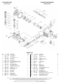
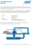
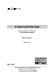
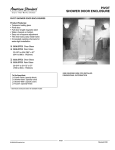
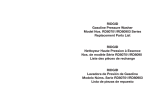
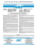
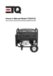
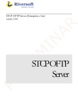
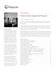
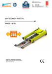
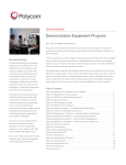
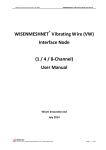
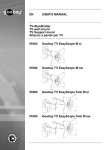
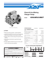
Direct-Drive Misting
Plunger Pump
Model1DX03ELS.MIST
Electric motor sold separately.
FEATURES
l Dual
plunger design provides a smooth liquid flow.
lSpecially
formulated Hi-Pressure Seals and concentrically
ground ceramic plungers assure maximum seal life.
lStacked
Stainless steel valve design for long life and easy
servicing.
lUltra
compact, direct-drive low speed unit for quiet
operation.
lIntegral
regulator with built-in by-pass to assure system
pressure control and pump protection.
SPECIFICATIONS
U.S. Measure
Metric Measure
Flow.......................................................................0.3 gpm
(1.14 lpm)
Maximum Discharge Pressure.................... 1200 psi
(85 bar)
MODEL 1DX03ELS.MIST
Stroke (Dual Plunger)..........................................0.078”
(2.0 mm)
Maximum RPM...............................................1725 rpm
(1725 rpm)
Inlet Pressure Range.................... Flooded to 60 psi
(Flooded to 4 bar)
Bore...........................................................................0.630”
(16 mm)
Crankcase Capacity............................................. 8.5 oz.
(0.25 l)
Maximum Liquid Temperature....................... 140°F(60°C)
Inlet Ports (1).................................................. 3/8” NPTF
(3/8” NPTF)
Discharge Port (1).......................................3/8” NPTM
(3/8” NPTM)
Shaft Diameter.......................................... 5/8” Hollow
(15.8 mm Hollow)
Weight..................................................................10.7 lbs.
(4.9 kg)
Dimensions.......................................7.12 x 7.75 x 6.29”(180 x 197 x 160 mm)
ELECTRIC HORSEPOWER REQUIREMENTS
All High Pressure Systems require a primary pressure regulating device (i.e. regulator,
unloader) and a secondary pressure relief device (i.e. pop-off valve, relief valve). Failure
to install such relief devices could result in personal injury or damage to pump or
property. CAT PUMPS does not assume any liability or responsibility for the operation
of a customer’s high pressure system.
Read all CAUTIONS and WARNINGS before commencing service or operation of any
high pressure system. The CAUTIONS and WARNINGS are included in each service
manual and with each Accessory Data sheet. CAUTIONS and WARNINGS can also be
viewed online at www.catpumps.com/cautions-warnings or can be requested directly
from CAT PUMPS.
MODEL
FLOW
PRESSURErpm
psipsi
10001200
U.S. barbar
gpmlpm 70 85
1DX03ELS.MIST
0.3 1.14 0.20 0.24 1725
DETERMINING
THE PUMP R.P.M.
DETERMINING
THE REQUIRED H.P.
DETERMINING
MOTOR PULLEY SIZE
Rated gpm
=
“Desired” gpm
Rated rpm
“Desired” rpm
gpm x psi
=
Electric Brake
1460H. P. Required
Motor Pulley O.D.
=
Pump Pulley O.D.
Pump rpm
Motor rpm
Refer to pump Service Manual for repair procedure and additional technical information.
EXPLODED VIEW
PLUNGER PUMP MODEL
February 2012
1DX03ELS.MIST
PARTS LIST
ITEM
5
8
10
11
15
20
24
25
27
32
33
37
38
48
49
53
64
65
70
71
90
98
99
P/NMATL DESCRIPTION
549360
547153
14041
55337
14488
547048
549608
548879
13832
547961
14179
92241
44428
44842
14179
542407
46229
542402
47215
548331
542403
46730
542405
STCP R
AL
NBR
NBR
STL
TNM
LDPE
CM
STL
RTP
NBR
—
NBR
NY
NBR
AL
STL
BB
NBR
BB
CC
NBR
S
Screw, HH (M6x14)
Cover, Bearing
O-Ring, Bearing Cover - 70D
Seal, Oil - 70D Bearing, Ball
Rod, Connecting
Plug, Oil Cap (Remove Before Startup)
Crankshaft, 1725 RPM, 5/8”, 2.0 mm
Bearing, Ball
Cap, Oil Filler w/O-Ring
O-Ring, Oil Filler Cap - 70D
Gauge, Bubble Oil w/Gasket - 80D
Gasket, Flat Flex, Oil Gauge - 80D
Plug, Drain
O-Ring, Drain Plug - 70D
Crankcase [2/05]
Pin, Crosshead
Rod, Plunger
Seal, Oil - 70D
Retainer, Oil Seal
Plunger (M16x27)
Washer, Seal - 90D
Retainer, Plunger (M6x35)
QTY
3
1
1
1
1
2
1
1
1
1
1
1
1
1
1
1
2
2
3
1
2
2
2
ITEM
100
106
120
121
160
161
163
164
166
167
168
172
174
185
188
255
283
300
310
400
446
460
P/NMATL DESCRIPTION
QTY
46233
48222
547357
13976
13965
545177
19285
545178
46764
46865
543988
142807
46759
49524
542406
549357
30516
990394
76054
76058
—
13969
107681
D
NBR
BB
NBR
NBR
S
NBR
S
S
S
PVDF
NBR
BB
BB
STZP
STCP R
STZP R
—
NBR
NBR
—
NBR
BB
Retainer, Seal 2
Seal, LPS w/S-Spg - 85D 2
Case, Seal 2
O-Ring, Seal Case - 70D 2
O-Ring, Inlet Valve Seat - 70D
2
Seat, Inlet
2
O-Ring, Seat - 70D
2
Seat, Discharge 2
Valve
4
Spring
4
Retainer, Spring 4
O-Ring, Plug - 90D
2
Plug, Valve (M20x1.5)2
Head, Manifold w/Modular Reg. Body 1
Screw, HSH (M6x60)
8
Screw, HSH (M6x60)
8
Assy, Bolt Mount
1
Kit, Oil Drain (Not Shown)
1
Kit, Seal (Inclds: 98,106,121,125)
1
Kit, Valve (Inclds: 160,161,163,164,166,167,168,172) 1
Regulator, Modular (See Indiv. Parts)
1
O-Ring, Discharge Fitting - 70D
1
Fitting, Discharge (3/8” NPTM)
1
Italics are optional items. See Tech Bulletins 002, 024, 036, 043, 055, 074 and 083 for additional information. R Components comply with RoHS Directive.
MATERIAL CODES (Not Part of Part Number): AL=Aluminum BB=Brass CC=Ceramic CM-Chrome-moly D=Acetal
LDPE=Low Density Polyethylene NBR=Medium Nitrile (Buna-N) NY=Nylon PVDF=Polyvinylidene Fluoride RTP=Reinforced Composite S=304SS STL=Steel STCP=Steel/Chrome Plated STZP=Steel/Zinc Plated TNM=Special High Strength
NOTE: Discard Key which may come standard with most motors and use only the key included in this kit.
INTEGRAL REGULATOR EXPLODED VIEW
SPECIFICATIONS
U.S. Measure
GPM...................................................................................0.3 gpm
PSI Range................................................................100-1200 psi
Discharge Port .........................................................3/8” NPTM
Metric Measure
(1.14 lpm)
(7-85 bar)
(3/8” NPTM)
INSTALLATION
An integral Regulator comes with each .MIST pump to provide
system pressure regulation and pump protection.
OPERATION
Set the regulator while the high pressure system is turned on.
Adjust the adjusting cap in small increments until the desired
system pressure is reached. Install a pressure gauge close to the
manifold head of the pump to check pressure during start-up and
periodically to monitor system performance.
System should be purged of air before operation. System liquid
must flow through the pump without discharge restriction to
assure full system pressure is reached.
SERVICE
The regulator should be serviced on the same schedule as the
seals in the pump.
1. Remove hex adjusting cap, spring and spring setainer.
2. Using a socket or wrench, remove piston retainer from the
unloader body.
NOTE: Loctite® 242® is used in the assembly process.
3. Using a needle nose pliers, pull the complete assembly, piston
stem through valve from the unloader body.
4. Using caution, grasp the valve with a pliers near the top next
to the valve retainer and unthread the piston stem using a flat
head screwdriver.
PARTS LIST
ITEM
PN MATL
402
46570 BB
408 549924 STCP R
410 549352 STCP R
412
46251 BB
414
28338 PTFE
415
22056 NBR
418
— BB
423
46249 BB
424
13966 NBR
425
46248 BB
426 46250 S
428
13969 NBR
429
17399 NBR
435 548193 S
436 46253 S
437
13963 NBR
468
33099 NBR
470
31088 NBR
DESCRIPTION
QTY.
Cap, Adjusting 1
Spring, Pressure
1
Retainer, Spring
1
Stem, Piston
1
Back-up-Ring, Piston Stem
1
O-Ring, Piston Stem - 70D
1
Assy, Piston (Included In Repair Kit)
1
Retainer, Valve
1
O-Ring, Valve Retainer (Outer) - 70D
1
Retainer, Piston
1
Washer
1
O-Ring, Piston Retainer - 70D
1
O-Ring, Valve Retainer (Inner) - 80D
1
Valve
1
Seat
1
O-Ring, Seat - 70D
1
Kit, O-Ring (Inclds: 414,415,424,428,429,437)1
Kit, Repair (Inclds: 418,428,436,437)
1
Italics are optional items. R Components comply with RoHS Directive.
MATERIAL CODES (Not Part of Part Number):
BB=Brass NBR=Medium Nitrile (Buna-N) PTFE=Pure Polytetrafluoroethylene S=304 STCP=Steel/Chrome Plated
5. Remove o-rings from valve retainer, and back-up-ring and o-ring
from piston stem. Examine o-rings and back-up-ring for cuts or
wear and replace as needed.
6. Examine the valve, valve retainer and piston stem for wear and
replace as needed.
NOTE: The seat will be damaged during removal and must be
replaced.
7. Replace seat and stem from repair kit.
8. Lubricate all o-rings for ease of installation and install on seat,
piston retainer, valve retainer and piston stem.
9. Assemble the washer, valve retainer with o-rings and valve
onto the piston stem with o-ring and back-up-ring and thread
together hand tight. Press complete assembly into body until
completely seated.
10. Apply Loctite® 242® to threads of piston retainer with o-ring.
Thread into body and tighten using a wrench.
11. Insert spring retainer and spring into the body.
12. Thread the adjusting cap into the body and set for system
pressure.
NOTE: If unit is infrequently used or periodically stored, o-rings
may become dry and will need to be replaced.
NOTE: This pump has an internally by-passed Regulator and if the pump is
operated with no flow out the nozzles (100% by-pass), heat damage will occur
to the seals and valve retainers in a short period of time.
Loctite and 242 are registered trademarks of the Henkel Corporation.
Model 1DX03ELS.MIST
4
5
4
3
1
2
1 Special, concentric, high-density, polished
solid ceramic plungers provide a true
wear surface and extended seal life.
2 High tensile strength, forged brass manifold head with built-in integral regulator
and eight mounting screws for exceptional
strength.
3 100% wet seal design adds to service life
by allowing pumped liquids to cool and
lubricate on both sides.
4 Stainless steel valves, seats and springs
provide corrosion-resistance, ultimate seating and extended life.
5 Unique design and specially formulated
Hi-Pressure Seals offer unmatched performance and seal life.
CAT PUMPS
1681 - 94TH LANE N.E. MINNEAPOLIS, MN 55449-4324
PHONE (763) 780-5440 — FAX (763) 780-2958
e-mail: [email protected]
www.catpumps.com
For International Inquiries go to www.catpumps.com and navigate to the “Contact Us” link.
PN 993281 Rev D 3/12 12063