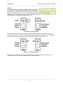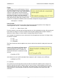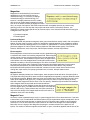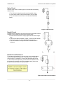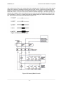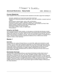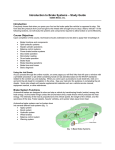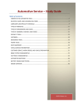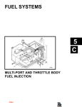
1
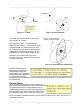
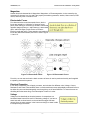
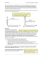
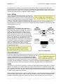
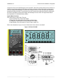
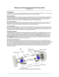
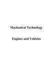
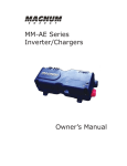
Electrical Circuits and Meters – Study Guide ©2004 Melior, Inc. ____________________________________________________________________________________ Course Objectives Upon completion of this course, technicians should understand and be able to apply their knowledge of: • Electrical properties: atomic structure, voltage, current, resistance, AC and DC • Digital Volt-Ohm Meters: setup, usage, and procedures • Making measurements on circuits • Electrical principles and variables, Ohm’s Law • Power, magnetism • Series, parallel, and series-parallel circuitry: characteristics, measurement methods, and applications • Reading and interpreting schematics • Components and applications: fuses, relays, solenoids, fixed and variable resistors, capacitors, and others Using the Job Sheets As you proceed through the online modules, on some pages you will find links that will open a window with a printable procedure or job sheet containing hands-on lab activities based on the NATEF standards related to the content you are studying. When you come upon a procedure or job sheet link, click on it and print the job sheet for completion in the shop. See your instructor for guidance in completing the job sheets. Some jobs sheets will require supplemental materials such as a vehicle service manual, equipment manual, or other references Module 1 Overview In order to properly diagnose and repair automotive electrical systems, the technician must first have an understanding of the basics underlying how those systems operate. In this section, we will look at electrical fundamentals and how they determine the construction and application of all automotive circuits. Let's begin first with a question … "What is Electricity"? Electricity may be defined as: "The movement of electrons through a conductor having the ability to do work". "Where does Electricity come from?" An easy answer might be: batteries, generators, a wall outlet, etc. But, let's take a closer look at the origin of electricity … Atoms The atom (figure 1-1) is composed of a nucleus including Protons (positive charge) and Neutrons (no charge) with revolving Electrons (negative charge). Each atom has a different number of electrons around its perimeter (figure 1-2). The movement of these electrons makes up electricity. ______________________________________________________________________________ ©2004 Melior, Inc. Electrical Circuits and Meters – Study Guide _____________________________________________________________________________________________ Figure 1-1 The Atom Figure 1-2 Atomic Structure Let's look at one specific example of an atom that we're familiar with …copper. The copper atom (figure 1-3) has 29 electrons around its nucleus located in different layers or shells around the nucleus, two in the first shell, eight in the second and 18 in the third shell for a total of 28. That leaves just one electron in the outer shell or "Valence shell", and this single electron is the one that does all of the electrical work. Atoms that have one or two electrons in the valence shell are called conductors. They include copper, gold, silver, aluminum, nickel, zinc, and others. That is why they are used to make wire. Figure 1-3 Free Electron from Copper Atom Atoms with a large number of electrons in the outer shell are called insulators and include rubber, plastics, etc. Those atoms that have around four electrons in the valence shell are called semiconductors. Semiconductors are used to make electronic components such as transistors, which will be discussed later. Electrical Energy When a sufficient electrical force (Voltage) is applied to a wire, the one "free" electron (figure 1-3) in the outer shell can no longer hold on to the atom. It then begins to carry its negative charge down the wire much like feeding Ping-Pong balls into a paper towel roll. The higher the applied voltage, the more electrons are moved. Those moving electrons operate the lights, horns, computers, and every other electrical device on your car or truck. If a substance has a large number of outer shell electrons, such as rubber, they don't let go as easily, and as such we use them as insulators. _____________________________________________________________________________________________ -2- ©2004 Melior, Inc. Electrical Circuits and Meters – Study Guide _____________________________________________________________________________________________ Magnetism Another electrical characteristic is Magnetism. Magnetism, or Electromagnetism, is also caused by the movement of electrons in a wire and is the property that makes generators, starters, blower motors, EGR valves, and many other "actuators" work. Electrostatic Forces Free electrons also create electrostatic forces, but the forces are caused by a "collection" of charges in one place, rather than by a movement of electrons. Recall that opposite charges (Protons +, and Electrons -) attract each other, and like charges (Proton-Proton or ElectronElectron) repel each other. These attractive and repulsive forces are called Electrostatics, and can be seen in figures 1-4 and 1-5. Figure 1-4 Electrostatic Fields Figure 1-5 Electrostatic Forces From this, we can now see how the basic structure of atoms is used to produce electricity and is applied to operating automotive systems. Electrical Properties In our study of Electricity, we will apply, measure, and calculate four different units: Voltage, Current, Resistance, and Power. Most students have no doubt used these terms and probably measured for them, but often they are used interchangeably even though they are in fact all different. To ensure that we are all talking about the same thing, a brief description of each is in order. Voltage Voltage can be described as electrical pressure. A comparison to a household water hose will be useful in discussing voltage. If you have a water hose with a closed nozzle on the end and the spigot has been opened, there is water pressure in the hose even though no water is able to escape through the nozzle. _____________________________________________________________________________________________ -3- ©2004 Melior, Inc. Electrical Circuits and Meters – Study Guide _____________________________________________________________________________________________ What actually causes voltage can be understood by recalling the earlier discussion about "free electrons." When there are more free electrons in one place as compared to another (such as between the positive and negative plates of a car battery), there is said to be a "Difference of Potential" or Voltage. The greater the difference between the number of electrons on one battery plate and the number on the other plate, the higher the voltage. A dead battery has the same number of electrons on the positive plates as on the negative plates. As we deal with electricity, we will see that this "electrical pressure" has a number of different names that all mean the same. They are: x Voltage or "V" x Electrical Potential x Potential Difference x Electromotive Force or "EMF" or "E" For the purposes of this course, we will use the term Voltage and either the V or the E designation. Also, remember that voltage is merely a "pushing" force and does not perform the real work in an electrical circuit. Current Current is the movement of electrons in a circuit. Like our voltage and water pressure analogy from before, current would be compared to the actual water moving through the hose. It is current, rather than voltage or power, which causes the lights to shine, the motors to turn, and the fuses to blow. Unlike voltage, which is the presence of electrons, current is the movement of electrons through some sort of conductor. The greater the number of electrons past a certain point, the greater the current or Amperage. Automotive systems vary from very high to very low current. For instance, the starter system typically is high current, being in excess of 100 Amps, whereas spark plug current is very low (many confuse high voltage with high current in ignition coils) at much less than one amp. Current is generally referred to in one of two terms: x Amperes, Amperage, Amps, or "A" x Intensity or "I" For our purposes, "A" and "I" will be used interchangeably. Conventional Current Flow vs. Electron Current Flow There are two different ways to look at current flow in a complete circuit; one is called "Electron Flow" and the other is "Conventional Flow". An understanding of the difference will help the technician in the use of electrical diagrams. The Electron flow theory says that since electrons do the work in a circuit and since electrons have a negative charge, then current must flow from the negative (-) battery terminal through the circuit and into the positive (+) terminal. This is used mostly by electrical engineers. Conventional flow theory says that since positive is greater than negative, then current must travel from + to -. Conventional flow is used by the automotive industry and as such, all of our electrical diagrams will be written in that format. DC and AC The current in any circuit will be one of two types: Direct Current (DC) or Alternating Current (AC). _____________________________________________________________________________________________ -4- ©2004 Melior, Inc. Electrical Circuits and Meters – Study Guide _____________________________________________________________________________________________ Direct current always flows in the same direction in a circuit, whereas Alternating current flows in one direction then reverses itself and moves in the opposite direction. Batteries and other steady state devices produce DC (figure 1-6). We will also see what is referred to as Pulsating DC. Pulsating DC is often incorrectly called AC although it is merely DC with a varying voltage. Technicians will find that the vast majority of automotive circuits operate on DC. Alternators and wheel speed sensors produce AC (figure 1-7). In order for a current to be AC, the current flow in a circuit must actually change direction. Figure 1-6 Direct Current or DC Figure 1-7 Alternating Current or AC Resistance Resistance is anything that opposes the flow of electrons. As the resistance in a circuit is decreased, the amount of current increases, and as the resistance increases, the current decreases. Comparing this once again to our water hose analogy, we find that if we use a larger diameter hose (less resistance) we will carry more water (more current). Conversely, a smaller hose (higher resistance) carries less water (lower current). Some resistance is necessary in any electrical application, as it is used to convert electrical energy to other forms such as heat (defogger grids) or light and to limit circuit current. Materials with low resistances, such as copper wire, we use as conductors, while materials with high resistances, rubber for instance, we use as insulators. What determines a substance's resistance? Several things, including: x The number of free electrons in the outer shell of the atom x Length of the conductor: A longer wire will have a higher resistance x Cross Sectional Area: The larger the circumference of a conductor is, the less its resistance. Example: A 1.0 mm wire (16 Ga.) has less resistance than a .35 mm wire (22 Ga.). x Temperature: generally, as a substance is heated, its resistance increases (exceptions to this rule will be seen later). Other factors also affect the resistance in a circuit, such as loose connections, corrosion, broken wire strands, etc. In contrast to the useful applications of resistance mentioned before, these will cause a circuit to operate inadequately or not at all. We will also become familiar with devices called "Resistors," whose function is to limit the current or voltage to another part of a circuit, and thus control its operation. _____________________________________________________________________________________________ -5- ©2004 Melior, Inc. Electrical Circuits and Meters – Study Guide _____________________________________________________________________________________________ The standard unit of measure for resistance is known as the "OHM" and is given the Greek symbol Omega (:). An Ohm is defined as: the amount of resistance that, when applied to a one volt circuit, will limit the current to one Amp. Thus, one volt through one Ohm equals one Amp. Students may choose to use either the Ohm symbol or a capital R to signify resistance. Source Voltage Source voltage is a term used to refer to the amount of voltage available to move electrons through a circuit. For most automotive applications, source voltage should be in the 12-14 Volt range. However, many of today's sensors operate on a 5V supply, while some actuators will use 7, 8, or 10 volts. Electronic computer components may use less than one volt. It is most important for the electrical technician to be aware of the amount of voltage that should be applied to a circuit to insure that misdiagnosis does not occur. Voltage Drop Voltage drop is very important in the diagnosis of electrical circuits. To explain voltage drop, let's return to our water hose analogy once again. At one time or another, we've all folded a hose in half to stop the water flow. When that happens, the water pressure remains the same between the kink in the hose and the faucet, while the pressure on the other side of the kink is zero or almost zero. This difference is called the pressure drop and it is principally the same as in electrical applications. Voltage drop is then defined as the difference between the voltage on the inlet side of a device compared to the voltage on the outlet side (figure 1-8). Comparing that value to a written specification will assist the technician in determining the fault with the system. Figure 1-8 Voltage Drop Digital Multi-Meters In order for a technician to diagnose an electrical problem, he must first test the system to determine which part is malfunctioning. Part of system testing requires the use of a Digital-Volt-Ohm-Meter (DVOM). A DVOM, also known as a Digital Multi-Meter (DMM) or just Multi-meter, is a versatile tool that allows for the measurement of Voltage, Current, Resistance, Capacitance, Frequency, Pulse Width, and other parameters. For our purposes in this course, we will use a Fluke 87 to represent a typical DVOM for our measurements. DVOM Our DVOM is a multi-meter that operates on a base 4 principle. Measurement ranges will be 4, 40, 400, 4000, etc. For instance, on a voltage setting, the maximum value that can be measured will be 4V, 40V, 400V, or 4000V depending on the scale selected. Some brands of meters are base 2 (2, 20, 200, 2000, etc.) or base 10 (1, 10, 100, 1000, etc.). Either type will work equally well as long as the technician learns to read the meter properly and accurately. Meters come with different levels of features, quality, and prices. A technician considering the purchase of a meter should keep two things in mind: 1) Does it have all the functions I need and, 2) What is its input impedance? Impedance is the input resistance a meter has. It prevents the meter from becoming a _____________________________________________________________________________________________ -6- ©2004 Melior, Inc. Electrical Circuits and Meters – Study Guide _____________________________________________________________________________________________ component of the circuit and affecting the circuit operation. Some lower quality meters have a tendency to "load" the circuit being tested and thus affect not only the operation of the devices itself, but also cause incorrect readings to be displayed. To prevent this "loading", look for a meter with high Input Impedance, generally the higher the better. This becomes even more critical when measuring electronic components, as some low impedance meters can actually cause damage to those circuits. Our digital meter has an input impedance of 10,000,000 Ohms (10M:). Typical Meter Functions This meter has four major areas. They are: x Input Terminals- four ports for input leads x Rotary Dial- with eight positions for different measurements x Pushbuttons- eight buttons for making changes in the display x Digital Display- gives information on values, scales, ranges, etc. Refer to the illustrations in figure 1-9 as we discuss each of the areas in more detail. Figure 1-9 Fluke 87 DVOM _____________________________________________________________________________________________ -7- ©2004 Melior, Inc. Electrical Circuits and Meters – Study Guide _____________________________________________________________________________________________ Input Terminals There are four input terminals at the bottom of the meter for inserting test probes. From the left, they are: 1) A (Amps): The red meter lead goes here for making current measurements up to a 10A maximum. Rotary dial is set to mA/A. 2) mA/PA (Milliamp/microamp): The red meter lead goes here for making current measurements up to a 400mA maximum. Rotary dial must be set to either mA/A or PA. 3) COM (Common ground): The black lead is inserted here for all measurements. 4) V : (Volts/Ohms): The red lead is inserted here for volts, ohms, and diode testing. Rotary dial set to a position other than mA/A or PA. This DVOM is also equipped with an alert feature that serves two purposes. It will emit a constant chirp if a lead is inserted into either the A or mA/PA terminal input and the rotary dial is not turned to the mA/A or PA position. It is designed to prevent damage to the fuses (and meter) by accidentally using the meter in an incorrect configuration. The alert also lets you check the fuses by putting the rotary dial in a nonamperage position (V or :) and inserting a lead into each of the amperage inputs to listen for chirp. If a fuse is blown, the alert will not sound. Make sure you check both inputs since there are two fuses, and ensure that the lead isn't connected to anything else before inserting into the terminal, as damage may occur. (5) Rotary Dial The rotary dial has eight positions for selecting the desired measurement. Starting from the Off position and moving clockwise, they are: x Off- No power is applied to the meter AC Volts x DC Volts x x mV Millivolts- up to 400 mV DC Continuity, Ohms, Capacitance x ͽͽͽͽͽ : Diode test x AC and DC Milliamps/ Amps x mA/A x PA AC and DC Microamps Pushbuttons Eight pushbuttons are used on this DVOM to change display readouts and some rotary dial functions. Beginning with the round yellow button and moving clockwise, they are: 6) Yellow Button Display Back-Light- Pressing the yellow button turns on the display light for easier viewing in dark places. The light automatically turns off after 68 seconds to preserve battery power. 7) Blue Button AC, DC, Resistance, Capacitance- The blue button will switch the display between AC and DC readouts when the rotary dial is in an amperage position. If the dial is in the : position, it changes from resistance (ohms) to capacitance (F). 8) Min Max- The Min Max button is part of a recording function that will catch and save the highest (max), lowest (min), and average values of Volts, Amps, or Ohms being tested. It is most useful for finding intermittent glitches. 9) Range- Manual ranging allows the user to change the display scale such as from 4V to 40V to 400V and so on. When a meter is first turned on it will come up in AUTO mode which will select the necessary range for the test being performed. 10) Hold- Sometimes it isn’t possible to take a measurement and read the display at the same time. If the Hold button is pressed, whatever measurement is taken will remain on the display after the leads have been removed. That readout will remain until a different measurement is made. 11) Continuity Beeper/Peak Min Max- When the rotary dial is in the : position, if a measured resistance is close to zero (continuity), the meter will beep. Pressing the button will disable the beep function. Peak Min Max function will be shown later as part of the Display features. _____________________________________________________________________________________________ -8- ©2004 Melior, Inc. Electrical Circuits and Meters – Study Guide _____________________________________________________________________________________________ 12) Rel ' Relative Delta- The Delta (triangle) is a mathematical symbol for change. The Rel ' button is used when the meter is making very small resistance measurements. Touching the leads together and pressing Rel ' will “zero out” any resistance there may be in the leads themselves and allow for a very precise resistance measurement. 13) Hz Frequency Counter and Duty Cycle- When the Hz button is pressed, the meter changes to measure cycles-per-second while a second press will read duty-cycle percentages. Duty-cycle percentages can also be used to determine dwell readings. Digital Display 14) The display is a digital and analog LCD readout screen for all meter functions. Turning the meter on while holding any button will allow the user to see all of the possible display segments on the screen. Each screen function is self-tested for one second when the meter is turned on and, to save battery power, the meter will also turn itself off if not used for a certain amount of time. The following explanations of the meter’s features will show each of the segments and its application. 15) Analog Display- Located along the bottom of the screen, the Analog Display is a 32 segment pointer that updates 40 times a second and is most useful for rapidly changing values. It is also useful in determining the value of capacitors. This feature does not operate in Frequency Counter or Peak Min/Max modes. 16) Analog Display Scale- Used in conjunction with the Analog Display from number 15, the Analog Display Scale applies values to varying signals that are easier to read than those on a continuously changing digital readout. It has a 0 to 10 display that scans up to four times for any given test value. Each scan is ¼ of the maximum range value. 17) r Analog Display Polarity- Located to the left of the Analog Display, it indicates whether the signal has a + or polarity. 18) Input Range- The Input Range in the lower right of the display will show the range of scale currently being used by the meter. This number shows the largest value that can be measured in that range such as 4V, 40V, 400V, 4000V, etc. Turning the dial to the mV scale will also display the mV display segment. Note that when the dial is set to mV, the display range can not be changed from 400 mV. 19) OL Out of Limits- Also referred to as “Overload”, an OL display indicates that the range is too low for the input being tested. For instance, if a 12 volt circuit is checked with the meter in a 4V range, the display will read OL. It tells the technician that a larger scale is needed (40V) to read the signal. Too often technicians interpret OL to mean that the system is malfunctioning rather than requiring a simple meter change. 20) AUTO Autorange- Located in the upper left corner, the AUTO feature will select the best range to use for a given measurement. The meter starts in AUTO mode each time it is turned on and the RANGE button must be used to manually switch scales. Caution must be used with Autorange as it automatically changes the scale in the lower right of the screen and the display can be easily misread. 21) Low Battery- This symbol alerts the user that the battery is low and readings may be affected. Replace 9V battery before continuing. 22) () Negative Polarity- When shown to the left of the digital numbers, the minus sign signifies a negative polarity reading (usually just reversed leads). This symbol is for the display numbers only and should not be confused with the r symbol for the analog scale. 23) This beeper symbol notifies the user that the continuity audio alert is active for the : scale. 24) ' Relative Mode- The ' (Delta) symbol displays to let the user know the leads have been “zeroed” for making precise measurements. Pressing the REL ' button turns this feature on and off. 25) 100 ms Normal Speed for Min/Max Mode- When in Min/Max mode, this symbol indicates that the recording function is operating in 100ms increments. The Peak Min/Max (beeper) button will change the record time to 1 ms increments for greater accuracy and usefulness in tracing intermittents. 26) Record- This identifier informs the user that the meter is currently recording the signal being probed. _____________________________________________________________________________________________ -9- ©2004 Melior, Inc. Electrical Circuits and Meters – Study Guide _____________________________________________________________________________________________ 27) Max- Pressing the Min/Max button once while in record mode will display the maximum value input during this record session. 28) Min- A second press of the Min/Max button will show the minimum reading taken in the current record memory. 29) Avg- On a third press of the Min/Max button, in 100ms mode only, an average of all readings taken in the record cycle will appear. 30) H Hold- This lets the user know the meter is operating in Hold mode and will keep the most current value on the display until a different reading is taken. Various other displays are shown on the screen to inform the user of the active measurement scale. These symbols are mostly found on the right side of the screen. They include: AC Alternating current or voltage DC Direct current or voltage V Voltage mV Millivolts A Amperage mA Milliamps PA Microamps nS Nanosiemens % Percentage : Ohms or Resistance k: Kilohms M: Megohms Hz Hertz (cycles per second) KHz Kilohertz PF Microfarad (capacitance) nF Nanofarad Digital Display Functions The DVOM display is a digital and analog LCD readout screen for all meter functions. Turning the meter on while holding any button will allow the user to see all of the possible display segments on the screen. Each screen function is self-tested for one second when the meter is turned on and, to save battery power, the meter will also turn itself off if not used for a certain amount of time. Reading the Meter As mentioned before, our DVOM makes it possible to change from one scale to another simply by moving the decimal point to the left or right. In the automotive field, we will use five primary unit sizes including base units and four prefix units, which are defined below: Mega Mega is the metric term for one million and uses the upper case symbol (M). If a measurement reads 1 M:, it is equivalent to 1,000,000 Ohms; likewise, 6,000,000 Ohms is given as 6M:. Kilo Kilo is the prefix for one thousand and uses the capital letter (K). One K: is equal to 1000 Ohms and an ignition coil secondary winding with 4000 ohms resistance would be shown as 4.00K:. Base Units Base, or root, units are the most commonly used and most familiar to the technician. They include Volts (V), Amps (A), Ohms (:), and Watts (W). Watts are a unit of Power to be covered later. Milli Milli corresponds to one thousandth of a base unit and has the lower case symbol (m). One thousand millivolts equals one volt and 12 volts equals 12,000 mV. Many relays operate in the 600 mA range and wheel speed sensors typically produce around 150 mV. Micro Micro is the smallest unit used in the automotive field and is given the Greek symbol mµ ( ). A microamp, for instance, is one millionth of an amp. Measurements in the micro ranges tend to be in electronic _____________________________________________________________________________________________ - 10 - ©2004 Melior, Inc. Electrical Circuits and Meters – Study Guide _____________________________________________________________________________________________ circuits. For a better understanding of how these units correspond to one another, refer to this table and figure 1-10. Mega Kilo Base Units milli micro MV KV volts mV µV MA KA Amps mA µA M: K: Ohms m: µ: Figure 1-10 Prefix Chart Each of the prefixes is a factor of 1000 as compared to the next, and converting is a simple matter of moving the decimal point three positions (three zeros) to the left or right (figure 1-11). For example, 3,500 ohms is a base unit (ohms) and if we need to know how many K: that would be we simply move the decimal point three places to the left since Kilo is to the left of Base on our chart. Likewise, if we have 1.2 amps and want to convert to mA, then we move three places to the right to get 1,200 mA. Figure 1-11 In order to add values, they must be in the same units. It is not possible to directly add 9 volts and 340 mv; one or the other must be converted first. Only eight of the above values are typically used. They are KV, V, mV, A, mA, M:, K:, and Ohms. _____________________________________________________________________________________________ - 11 - ©2004 Melior, Inc. Electrical Circuits and Meters – Study Guide _____________________________________________________________________________________________ Scaling If a technician is trying to measure 10,000,000 ohms with the meter set on a 400 : range, the display will read OL since the maximum readable value is 400 ohms. After switching the meter to the 40 M: range, the display will show 10.00. Do not confuse this with 10 ohms! That is why it is so important to be aware of the scale currently being used, especially if Auto Ranging is active (figure 1-12). Figure 1-12 Very Large Values The opposite condition can also be confusing in dealing with small values. Imagine you are trying to measure 25 mA on a 40 A scale. The meter would basically display zero (00.03). However, by switching to a 4A (4000mA) scale, the readout now shows 0025 mA which is accurate (figure 1-13). Figure 1-13 Very Small Values A technician who is careful to use the correct unit setting (Volt, Amp, Ohm) and the right scale, can consistently rely on the meter information to assist in proper diagnosis. _____________________________________________________________________________________________ - 12 - ©2004 Melior, Inc. Electrical Circuits and Meters – Study Guide _____________________________________________________________________________________________ DVOM Measurements Voltage Measurement: To properly configure a meter for voltage measurements, follow these steps and refer to figure 1-14. x Insert the meter leads into the COM and V: inputs x Turn the rotary dial to the AC or DC Volt position x Place the leads across the component to be tested (voltage drop) x Apply power to the circuit Figure 1-14 Voltage Measurement Current Measurement: To measure current, follow this procedure and refer to figure 1-15. 1. Insert the meter leads into the A and COM inputs 2. Turn the rotary dial to the mA/A position 3. Make an open in the circuit 4. Place the meter leads to complete the circuit (leads must be inserted so that all current flows through meter) 5. Apply power to the circuit Caution: To prevent blown fuses, check your meter installation thoroughly before applying power. Remember, in this mode, all of the current in the circuit will pass through the meter. Caution: Never place leads across a component when measuring amperage. Figure 1-15 Current Measurement _____________________________________________________________________________________________ - 13 - ©2004 Melior, Inc. Electrical Circuits and Meters – Study Guide _____________________________________________________________________________________________ When measuring circuit current, always begin with the red lead in the A (10 amp) input terminal. The lead may be moved to the mA input only after you have determined that the current is below the maximum (1A) rating for that terminal. Resistance measurement: Resistance measurements are made according to these steps and the figure in 1-18. 1. 2. 3. 4. 5. Power must be off Insert the meter leads in the COM and V: inputs Turn the rotary dial to the : position Place the leads across the component Do not allow your fingers to touch the ends of the leads since it will change the reading! NOTE: When measuring resistance, it is important to make sure the power is off. This is done not because it will damage the meter, but because it will give false readings. Figure 1-18 Resistance Measurement _____________________________________________________________________________________________ - 14 - ©2004 Melior, Inc. Electrical Circuits and Meters – Study Guide _____________________________________________________________________________________________ Module 2 Overview In Module 1 of this series, we introduced the concepts of voltage, voltage drops, current, and resistance, as well as digital multi-meter usage. In this module, we expand on the applications of those concepts as well as adding Power, Ohm's Law, and Magnetism. General Electrical Rules Applications of voltage, current and resistance follow some general electrical rules: If the Resistance remains the same: x As voltage increases, current increases x As voltage decreases, current decreases If the Voltage remains the same: x As resistance increases, current decreases x As resistance decreases, current increases Ohm's Law In electrical circuitry, if any one of the three variables (V, A, :) changes, it will affect at least one of the other two. An equation allows us to determine the effect of that change called Ohm's Law. Ohm's Law is expressed as follows: E = I x R or V = A x : In this equation, x "E" = Electromotive Force (Voltage) x "I" = Intensity (Amperage) x "R" = Resistance (Ohms) Simply by rearranging the variables, we can calculate a value for any one, if we know the other two. Variations **The primary formula for Ohm's Law is: E = I x R or Volts = Amps x Ohms. This tells us that if we multiply the current (in amps) times the resistance (in ohms), we can find the applied voltage or voltage drop. **To find an unknown current we use: I = E/R or A = V/: Divide the voltage by the resistance to find the current. **Resistance is found with: R = E/I or : = V/A Divide the voltage by the current to find resistance. Ohm's Law Solving Circle The solving circle in figure 2-1 can be used to determine which formula to use. Cover the letter for the value you don't know, and the formula to use will be shown by the remaining two. For example, if you want to know the voltage drop in a circuit, just cover the letter E, which will leave IxR. Covering the "I" will give E/R, and if "R" is covered, then E/I remains. Figure 2-1 OHM's Law Solving Circle _____________________________________________________________________________________________ - 15 - ©2004 Melior, Inc. Electrical Circuits and Meters – Study Guide _____________________________________________________________________________________________ In the circuit shown in figure 2-2, the source voltage is unknown. The resistance of the load (shown as a resistor) is 2 ohms and the current flow is 6 amps. To solve for the missing voltage we apply: Volts = Amps x Ohms [E=IxR] Inserting the known values … Volts = 6 Amps x 2 Ohms Then multiply, and we have … Volts = 12 Therefore, source voltage in the circuit is 12 volts. Figure 2-2 Calculate voltage using Ohm's law In figure 2-3, the current is unknown. The load resistance is given as 2 ohms, and the source voltage is known to be 12 volts. To solve for the current we use: Amps = Volts/Ohms [I=E/R] Inserting the known values … Amps = 12 Volts/2 Ohms Perform the division to solve … Amps = 6 Circuit current is now known to be 6 Amps Figure 2-3 Calculate current using Ohm's law In figure 2-4, the resistance is unknown. The given source voltage is 12 volts, and the current flow is 6 amps. Find the resistance by using: Ohms = Volts/Amps [R=E/I] Our known values yield … Ohms = 12 Volts/6 Amps After dividing we find … Ohms = 2 This circuit has a total resistance of 2 Ohms. Figure 2-4 Calculate resistance using Ohm's law _____________________________________________________________________________________________ - 16 - ©2004 Melior, Inc. Electrical Circuits and Meters – Study Guide _____________________________________________________________________________________________ Power Unlike Voltage, Current, and Resistance, Power is not a direct measurement for an electrical property. Power is the output, or rate of work, performed by a machine. As with gasoline and diesel engines, motors are rated as to the number of horsepower they produce. However, many other electrical devices (eg. light bulbs) are rated by the amount of power they consume rather than by output. Power (symbol "P") is expressed in Watts but can be converted to horsepower using this equation: 1 Horsepower = 746 Watts Power Formula As mentioned earlier, Power is not a direct measurement but rather the product of the Voltage and Current applied to a device. To calculate the power consumed use: P=IxE or Watts = Amps x Volts From this formula, we can see that one Watt is equal to one Volt multiplied by one Amp. We can also see that if either the voltage or current is increased, then the power (wattage) also increases. Likewise, a decrease in either voltage or current causes a corresponding reduction in power. As an example, let's assume we have a device with 120 Volts applied and a Current of 10 Amps. Using the formula, we obtain: P=IxE P = 10A x 120V P = 1200 Watts The Power formula can then be applied to any circuit or device where both the voltage and current are known. If either I or E is unknown, the Power formula can be expanded and calculated with other quantities that are known. For instance, we know that E=IxR and if a substitution is made, we have: P=Ix(IxR) or P=I2xR which allows us to use I and R to calculate Power instead of I and E. Likewise, since I=E/R then: P=(E/R)xE or P=E2/R if I is unknown. As a general rule, those things that are rated in watts consumed have a different form of output. For instance, light bulbs are rated in watts but have an output in lumens. Audio speakers have an output based on how much air they move, and resistors, also rated in watts, put out heat. Electric motors, as mentioned before, are an exception in that they are rated in horsepower output rather than watts consumed. _____________________________________________________________________________________________ - 17 - ©2004 Melior, Inc. Electrical Circuits and Meters – Study Guide _____________________________________________________________________________________________ Magnetism Magnetism is used extensively in automotive applications to convert electrical energy to mechanical energy, or conversely, to change mechanical energy to electrical energy. For instance, if we apply electrical current to certain devices we can create lateral (straight line) motion such as in the starter solenoid (to engage the starter drive), or to open fuel injectors. Still other components will use applied electricity to produce rotary (spinning) motion, as is the case with fuel pumps and starter motors. Generators, however, use magnetism to change motion (belt driven) to electrical output. In the automotive field there are two types of magnets used. They are: x Permanent magnets x Electromagnets Permanent Magnets We are all familiar with permanent magnets, those gray colored devices usually made in bar or horseshoe shapes. It's likely most of us have a number of permanent magnets attached to our refrigerators holding up out-of-date notes and drawings done by our children or grandchildren. In cars and trucks we will find permanent magnets in Crank Position Sensors (distributor and distributorless types), Cam Position Sensors, ABS sensors, some fuel pumps, Vehicle Speed sensors, and new style starters. Electromagnets Electromagnetism occurs when an electrical current is passed through a conductor and creates a surrounding magnetic field. Electromagnets usually consist of a wire wound around a metal core and powered by an electrical source. Some students may have done an experiment in school where a wire was wrapped around a nail with both wire ends attached to a battery to form an electromagnet. The device could then be used to pick up paper clips. Examples of electromagnetic automotive applications include starter solenoids and fuel injectors, as mentioned earlier, as well as some EGR valves, relay contacts, transmission shift and pressure-control solenoids, numerous vacuum control valves, blower motors, cooling fans, wiper motors, fuel pumps, generators and, of course, old style starter motors. Magnetic Fields All magnets, whether permanent or electromagnet, have two poles: North and South. Like poles (N-N or S-S) repel and unlike poles (N-S) attract. Automotive applications all operate by magnetic attraction rather than magnetic repulsion. Between these two poles are invisible lines of force called the "flux lines" which make up the magnetic field (figure 2-5). A magnet with many flux lines (or high flux density) is strong whereas a weak magnet has few flux lines or low "flux density". Students may be familiar with instances where magnets have become weak and caused operational problems such as a Crank Position Sensor that causes the engine to cut out at higher rpm's or an ABS sensor that drops to zero while the vehicle is still moving. These problems are most often caused by a drop in the flux density of the magnet itself but will not be seen in a resistance check of the wire winding. Magnetic Force As electric current is passed through a wire, it creates magnetic lines of force around the wire. If that wire is wound into a coil, it creates North and South Poles much like a permanent magnet except that it can be turned on and off and made stronger or weaker (figure 2-6). Because many metals are good magnetic conductors, a core is often used in the center of the coil to enhance the strength of the electromagnet. Most often, the core is part of the design like the plunger in a starter solenoid or the pintle in a fuel injector. If a number of different magnetic devices were cut open, it would be apparent that the size of the _____________________________________________________________________________________________ - 18 - ©2004 Melior, Inc. Electrical Circuits and Meters – Study Guide _____________________________________________________________________________________________ wire and the number of turns around the core are not the same. For various applications, designers will change the wire size, the number of turns, the diameter of the coil, the length of the coil, and the applied current to get just the right amount of magnetic force needed for a particular use. Figure 2-6 Electromagnetic Fields Relays A relay is an electromagnetic device that operates as an on-off switch. It uses a small coil current to control a larger contact current. Inside a relay, there is a coil of wire and one or more sets of contacts. Applying a small current to the coil creates a magnetic field which "pulls in" the contact(s) and closes the circuit sending the larger "controlled" current to the load device; eg. fuel pump, ECM, etc. (figure 2-7). Relays are classified as Normally Open (N.O.) or Normally Closed (N.C.) depending on whether the contacts are open or closed with the coil deenergized. Figure 2-7 Relays Solenoids A solenoid is an electromagnetic device that uses applied current to produce lateral (back and forth) motion (figure 2-8). Solenoids such as fuel injectors and transmission shift valves have a movable metal core inside the coil. As current is applied to a coil, the electromagnetic field it produces either pushes or pulls the core and opens or closes a valve, or engages a starter drive. The terms relay and solenoid are sometimes used interchangeably but in fact, they are two different things. Figure 2-8 Solenoid (fuel injector) _____________________________________________________________________________________________ - 19 - ©2004 Melior, Inc. Electrical Circuits and Meters – Study Guide _____________________________________________________________________________________________ Motors Electric motors also work on the principles of electromagnetism, but unlike relays or solenoids, their function is to produce rotary (spinning) motion. Motors have two primary components: an Armature or rotating element and a stationary Field Coil. Motors can have permanent magnet armatures with wound field coils, permanent magnet field coils with wound armatures, or have both the armatures and field coils wound. Permanent magnet armature motors are used in Alternating Current applications and are not common in automotive applications. In a DC electric motor, voltage is applied to the armature winding through a pair of carbon brushes and a split ring called a commutator. The commutator has the effect of alternately changing the poles of the armature coil from north to south and back again for each half revolution of the armature. For example, let's assume that a point on the outer Field Coil has a north orientation. The half of the armature that has a south polarity would be attracted to that point and would cause the unit to rotate as they pulled closer. However, just as the two points align, the commutator switches the armature polarity and the new south point is now on the opposite side of the armature winding which causes it to attract the north point on the field coil and the rotation continues. Electromagnetic Induction We have already seen that we can create a magnetic field with an applied current, but now we will find that we can also produce a current from a magnetic field. The process is called "electromagnetic induction". When a magnetic field and a wire are moved near each other, a voltage is produced in the wire that causes a current to flow. This is called an "Induced Voltage". As long as the movement continues, the current will continue, but if the motion stops, the current will stop. Applications of electromagnetic induction are typically in generators or alternators and in transformers or ignition coils. Generators and alternators are designed similarly to motors in that they have a field winding and an armature winding. How they differ in terms of their induction is this: generators have a coil that turns and a magnetic field that is stationary whereas alternators have a magnetic field turning inside of a stationary coil. The amount of induced voltage (and therefore current) depends on several factors: x Strength of the magnetic field x Speed of motion between the coil and the magnetic field x Number of conductors in the coil Transformers Transformers are another type of device that works by electromagnetic induction. A transformer is constructed with two separate windings (a primary and a secondary) wrapped around a common metal core (figure 2-10). When alternating current or pulsating DC current is applied to the primary winding a voltage is created, or induced, into the secondary winding. _____________________________________________________________________________________________ - 20 - ©2004 Melior, Inc. Electrical Circuits and Meters – Study Guide _____________________________________________________________________________________________ Figure 2-10 Transformers Transformers are classified as either Step-up or Step-down. A Step-up transformer will create a higher voltage in the secondary winding while a Step-down will cause a lower voltage. Your local electrical substation has a series of Step-down transformers to reduce the voltage before it enters your house. The Step-up or Step-down ratio is determined by the number of turns of the wire used in both the primary and secondary windings. One other thing to keep in mind is that the primary and secondary currents will also change except they go up as voltages drop and decrease as voltages increase. As an example, let's use the most common transformer in automotive use - the ignition coil. In a typical ignition coil the ignition module will apply 12 Volts pulsating DC with a current of between 4-10 Amps. We'll use 6A as an example. The voltage that comes from the secondary to fire the spark plugs is typically between 5,000 Volts and 20,000 Volts (some can go as high as 80,000 Volts). Our example will use 12,000 V. If the input voltage is 12 Volts and the output voltage is 12,000 Volts, then the step-up ratio is 1000:1 (12,000/12), while at the same time the current will drop by the same ratio from 6A to .006 Amps (6/1000). A Step-down transformer will likewise increase the output current by the same ratio that the voltage was decreased. It's also interesting to note that the input power and the output power for a transformer are basically identical. Ignition coils: 1. The primary coil resistance will typically measure between .5: and 1.0: and the secondary will have a resistance of around 5K: to 15K:. 2. Distributor type coils are sometimes called autotransformers because the primary and secondary coils are physically connected at the + terminal. _____________________________________________________________________________________________ - 21 - ©2004 Melior, Inc. Electrical Circuits and Meters – Study Guide _____________________________________________________________________________________________ Module 3 In Module 2 of this series, we looked at the applications of Voltage, Current, Resistance, Power, and Magnetism. Now, we will apply these, as well as Ohm's Law, to electrical circuits. Electrical circuits are divided into three categories known as Series, Parallel, and Series-Parallel. Although there are differences in the three, which will be seen later, we will examine some fundamental similarities that exist in all electrical applications, both automotive and non-automotive. Figure 3-1 Circuit elements Source The first requirement for any circuit is a source of power. Automotive applications generally have two primary power sources: the battery and the generator. Protection A fuse, circuit breaker, or fusible link is needed to prevent wiring damage from excessive circuit current. Control A control device can either turn a load on and off, or it can vary if a changing output is required. Loads such as headlights or fan motors will be either on or off and will use switches or relays as controlling devices. However, applications such as instrument panel dimming, fuel injection, and transmission valves have variable outputs and will be controlled by potentiometers, transistors, and Pulse Width Modulation computer signals. Load A load is any part or component in a circuit that causes resistance to the current flow in the circuit. All circuit loads will have a corresponding voltage drop. Loads can be devices such as bulbs, motors, and actuators as well as unintentional items including bad connections and corrosion. Ground All circuits must have a complete path to operate. Automotive applications all terminate at ground or battery negative. A ground return can be either hard-wired to the battery negative or chassis grounded through the metal pieces of the vehicle. Case-grounded components have an internal connection to their metal casing and become chassis grounded when installed in the vehicle. _____________________________________________________________________________________________ - 22 - ©2004 Melior, Inc. Electrical Circuits and Meters – Study Guide _____________________________________________________________________________________________ Series Circuit A Series circuit is the most basic type of circuit and has the following characteristics: x The individual voltage drops add up to the applied voltage x Current is the same at any point and flows in only one path x The total resistance is the sum of the individual resistances (loads) Figure 3-2 Series Circuit Parallel Circuit A parallel circuit is defined as one that has more than one path to make a complete circuit. Parallel circuits have the following traits: x Each branch has the same voltage applied and the same voltage drop x There is more than one branch, or path, for current to flow and the total current is the sum of the individual branch currents x The total resistance is always less than the smallest branch resistance Figure 3-3 Parallel Circuit Parallel Circuit Resistance To calculate total resistance in a series circuit, we can simply add the values of the individual resistances. In a parallel circuit, it is a little more involved. For example, in a circuit with three branches having 10, 20, and 30 ohms respectively, we know the total resistance must be less than 10 ohms (the value of the smallest branch) rather than the 60 ohms we would have in a series circuit. Figure 3-4 Parallel circuit resistance _____________________________________________________________________________________________ - 23 - ©2004 Melior, Inc. Electrical Circuits and Meters – Study Guide _____________________________________________________________________________________________ The sum of the reciprocals can also be expressed as: 1/RT=1/R1+1/R2+1/R3+1/R4+ Applying our values we have: 1/RT = .1 + .05 + .033 1/RT = .183 RT = 1/.183 RT = 5.46ȍ The Windows calculator on your computer can be used to make these calculations. You can open the Windows calculator by clicking on Start, and then Run. Type the word "calc" without the quotes in the space provided and then click the OK button. Try both of these methods using our example numbers of 10, 20 and 30ȍ. If your calculator has a 1/x (inverse) key, the formula can be entered by pressing the calculator keys (shown in parentheses) in order as follows: R1 (1/x) (+) R2 (1/x) (+) R3 (1/x) (+) (1/x) answer If no inverse key is available, then figure the resistances by pressing the calculator keys (shown in parentheses) in order as follows: 1(÷) R1 (=) (M+) 1(÷) R2 (=) (M+) 1(÷) R3 (=) (M+) 1(÷) (MRC or MR) (=) answer (1/x is the inverse key, + is the addition key, M+ is the Memory Add key, MRC or MR is the Memory Recall key, is the Division key, and = is the Equals key) Parallel Circuit Current Unlike series circuits, where current is always the same, parallel circuits can have a different amperage value for each branch in the circuit. You will recall that the voltage drop is the same for parallel branches, but if each branch has a different resistance, then Ohm's Law can be used to determine that the branches have different currents. The total circuit current can then be found simply by adding the branch currents. Figure 3-5 Parallel circuit current _____________________________________________________________________________________________ - 24 - ©2004 Melior, Inc. Electrical Circuits and Meters – Study Guide _____________________________________________________________________________________________ Given the circuit from the previous page, what is the total current? We know that since the two bulbs are in parallel, their voltages are equal at 12V each. The bulb on the left has a resistance of 6: and applying Ohm's Law we have: I1 = E1/R1 or I1 = 12V/6: so I1 = 2 Amps Similarly, the 24 : right bulb has a current given by: I2 = E2/R2 or I2 = 12V/24: so I2 = .5 Amps Total current is therefore: IT = I 1 + I2 = 2 A + .5A = 2.5Amps Now, calculate the total current if the left bulb is 2: and the right bulb is 12: … Series-Parallel Circuits Sometimes it is necessary to reduce the amount of voltage drop across the branches of a parallel circuit to less than source voltage. To accomplish this we use a circuit called Series-Parallel. A Series-Parallel circuit works by inserting a resistor in series with a parallel network. The series resistor will cause a voltage drop that leaves less voltage available to the branch loads and therefore reduces their currents. How would you calculate the total resistance of a SeriesParallel circuit? Calculate the parallel portion of the series-parallel circuit just as you would for any parallel network and then add the series resistance to that total. How would you find the total current? Use the Ohm's Law formula I=E/R just as you would for any circuit. In this case, the voltage is the 12 volt source and the resistance is the series-parallel value determined in the last step. _____________________________________________________________________________________________ - 25 - ©2004 Melior, Inc. Electrical Circuits and Meters – Study Guide _____________________________________________________________________________________________ Figure 3-6 Series-Parallel Circuit This illustration of a Dash-Light circuit shows how changing the resistance of the rheostat (dimmer control) varies its voltage drop and, in turn, changes the voltage available to the dash bulbs, which controls their brightness. _____________________________________________________________________________________________ - 26 - ©2004 Melior, Inc. Electrical Circuits and Meters – Study Guide _____________________________________________________________________________________________ Circuit Components With an understanding of Voltage, Current, and Resistance, we can now turn our attention to the devices that determine those values. Circuit Protectors Three types of circuit protectors used in modern automotive applications: fuses, circuit breakers, and fusible links. The primary function of these devices is to protect the wiring from damage should a circuit failure cause excessive current. Although circuit protectors are rated in amps, it is actually the heat caused by too much current that causes the device to open the circuit. Fuses Fuses are the most common circuit protectors in automotive use and are rated from 5 A to 80 A. They are one-use devices with a metal strip inside that melts from the heat caused by exceeding the current rating of the strip. The most common fuse types are the Auto Fuse, Mini Fuse, and Maxi Fuse (figure 3-7). As shown in the graph on the next page (figure 3-8), different colors are used to identify the amperage values of the various fuses. Figure 3-7 Assorted automotive fuses Figure 3-8 Fuse Colors Circuit Breakers Unlike fuses, circuit breakers can be reset, either manually or automatically, and reused. Circuit breakers are either "cycling" or "non-cycling.” A circuit breaker is made with a bi-metallic strip that operates much like the thermostat in many homes. As current passes through the strip it creates heat, which causes the two metals to expand, but at different rates. When one expands faster than the other, the strip bends and opens a contact which stops current flow through the circuit. In a "cycling" type of breaker, the bi-metallic strip will cool, after the _____________________________________________________________________________________________ - 27 - ©2004 Melior, Inc. Electrical Circuits and Meters – Study Guide _____________________________________________________________________________________________ current stops, and return to its original shape, which closes the circuit to current flow once again. A mechanical turn signal flasher works this way also. A "non-cycling" type of breaker will open from excessive current as well but must be manually reset. Another type of circuit breaker is the solid state device called a PTC (Positive Temperature Coefficient). PTCs have no moving parts and are commonly used in window motors and door lock actuators to protect the circuit from damage should a control switch become stuck or in case a limit switch fails. They can also be used as end-of-travel stops without a limit switch (figure 3-9). Figure 3-9 Power Window schematic with PTC's A PTC is a thermistor that works by greatly increasing its resistance when too much current generates excessive heat in the device. As the resistance increases, the current in the circuit is reduced which protects the wiring from damage. Fusible Links Like fuses, fusible links are single use devices that melt internally from heat caused by too much current (figure 3-10). Although they look like typical wires, fusible links have an insulation designed to withstand a greater amount of heat than regular wire insulation. This prevents inadvertent shorting to ground during a failure caused by excessive current. Fusible links are being used less in modern applications as fuses with higher amperage ratings have become available. _____________________________________________________________________________________________ - 28 - ©2004 Melior, Inc. Electrical Circuits and Meters – Study Guide _____________________________________________________________________________________________ Figure 3-10 Fusible Link When replacing an open fusible link, never exceed nine inches in length and use a link that is four sizes smaller than the circuit wire. For example, a 14 gauge wire would be protected with an 18 gauge fusible link. This will ensure that the link burns before the circuit wire. An open fuse link can also be verified by pulling its ends to see if it stretches, which shows failure. Switches Switches are simply on-off devices used to open or close an electrical circuit. There are various types of switches that are categorized by the number of positions they have, as well as the number of circuits they control. Some of the most common types are given below: Single Pole Single Throw (SPST)- Controls one circuit with two positions (ON-OFF) Single Pole Double Throw (SPDT)- One circuit with three positions (two on positions with a center off position) Double Pole Single Throw (DPST)- Two circuits with two positions Double Pole Double Throw (DPDT)- Two circuits with three positions Switches are rated by the amount of current the contacts can carry. Figure 3-11 Switch type examples Resistors Resistors are devices, made of carbon or ceramic, which are used to limit the voltage or current in a circuit. They can be either "fixed" or "variable" and will be rated both in terms of value (ohms) and power (watts). The value of a "fixed" resistor can be read from its color bands. Each resistor has several color bands that should be offset to one end. Hold the resistor so that the color bands are on your left, note the colors, and compare them to the chart in figure 3-12. _____________________________________________________________________________________________ - 29 - ©2004 Melior, Inc. Electrical Circuits and Meters – Study Guide _____________________________________________________________________________________________ Figure 3-12 Resistor color coding Some resistors, such as those found in blower motor circuits, are wire-wound and have no color bands (figure 3-14). Resistive values for those should be printed in service manuals. Figure 3-14 Blower Motor Resistors _____________________________________________________________________________________________ - 30 - ©2004 Melior, Inc. Electrical Circuits and Meters – Study Guide _____________________________________________________________________________________________ Just as they have an Ohms value, resistors also have a wattage value. Recall from module 2 that wattage (Power) is the product of Voltage and Current given by P=IxE. As such, resistors are not rated in either voltage or current but rather in watts to limit their heat exposure. For example, if a resistor is rated at 10 Watts and is used in a 12 Volt circuit, then the maximum allowable amperage is .833 Amps [I=P/E]. If we decrease the voltage by half to 6 volts then the current can double without damaging the resistor [P=IxE or P=1.66 amps x 6 volts or P=10 watts]. Most often the wattage rating of a resistor is determined by its size. Some of the most common sizes are shown in figure 3-13. Figure 3-13 Resistor sizes by watts Figure 3-15 Steering Wheel Controls _____________________________________________________________________________________________ - 31 - ©2004 Melior, Inc. Electrical Circuits and Meters – Study Guide _____________________________________________________________________________________________ Variable Resistors A variable resistor is one whose value can be changed either manually, by turning a knob or sliding a lever, or automatically by altering the temperature. The range of values for any variable resistor is determined by the material used in its construction, or by the size and number of turns in wire-wound units. Some variable resistors change at the same rate throughout their range (linear), while others will change more quickly at first then taper off later (non-linear). Rheostats A rheostat is a mechanically operated variable resistor with two connections. It is used to change the current in a circuit based on its position. Dash light dimmers, some fuel gauge sender units, and wiper delays are all applications of rheostats. Potentiometers Potentiometers are also mechanically operated but, unlike rheostats, they act as voltage dividers rather than as current limiters. "Pots" have three connections and are commonly used as sensors to send varying voltage signals to a vehicle's computers. Some examples of potentiometers are Throttle Position sensors, EGR Position sensors, Accelerator Pedal Position sensors, and transistorized Dimming Control. Thermistors Thermistors are solid state variable resistors that operate based on the amount of heat applied. There are two types of thermistors, Positive Temperature Coefficient (PTC) and Negative Temperature Coefficient (NTC). A PTC will increase its resistance as the temperature increases whereas NTCs will have a decreased resistance from increased temperature. PTCs are commonly used to protect circuits from excessive current and are found in applications such as window motors and door locks. NTCs, however, are most often used for sensing temperature and to input voltages to computers. Typical NTC devices include Engine Coolant Temperature, Intake Air Temperature, Transmission Fluid Temperature, Heat and Air Conditioning Temperature, etc. Capacitors Capacitors are devices that store electrical charges and behave like temporary batteries. Technicians may have seen them used as filters on alternators or radios to reduce noise, or even in older point-style distributors as condensers. By controlling how quickly they charge and discharge, we can also use them as timers. Capacitors basically consist of two metallic plates separated by an insulator called a "dielectric." Dielectrics can be something as simple as a piece of paper. A simple capacitor can be made by placing a sheet of paper between two equal sized sheets of aluminum foil. Wrap all three sheets around a paper towel roll (don't let the aluminum sheets touch) and attach a connector wire to each piece of aluminum foil. That is the basic construction of a capacitor. There are two types of capacitors, electrolytic and non-electrolytic. Electrolytic capacitors have both a positive and negative end while non-electrolytics can be inserted in either direction. The symbol for an electrolytic capacitor is, and for a . non-electrolytic Since the plates in a capacitor do not touch, it acts like an open in a circuit and will not pass DC current (figure 3-15). Figure 3-15 Electrical Charges on capacitor plates _____________________________________________________________________________________________ - 32 - ©2004 Melior, Inc. Electrical Circuits and Meters – Study Guide _____________________________________________________________________________________________ When a capacitor is connected to a voltage source as in figure 3-15, there is a brief period of current flow in the circuit while it charges. As a capacitor charges, electrons flow from the power source to the negative plate until the voltage across the capacitor is equal to the source voltage. Current flow stops when the voltages equalize. If the source voltage increases, the capacitor will charge to the higher value, but if the source voltage decreases, the capacitor will discharge until the voltages are equal once again. Once a capacitor is charged, it can maintain that charge for an extended amount of time (sometimes for years) if the ends are not allowed to come into contact. Some of the charge, however, may be lost internally through the dielectric material. This loss is called "leakage.” Units Capacitors are rated in terms of their storage capacity, called Farads, as well as their working voltage. The Farad (F) is a measure of the number of electrons a capacitor can store and is very large. Most applications will be rated in microfarads (PF) or nanofarads (nF). A microfarad is one-millionth of a farad and a nanofarad is one-billionth of a farad. When selecting a capacitor for a given application, make sure the working voltage rating is higher than the source voltage to prevent damage. A capacitor’s rating is determined by three factors: x The area of the plates x The distance between the plates x The dielectric material Capacitors in Parallel If two or more capacitors are placed in parallel in a circuit (figure 3-16), the total capacitance is determined by adding the individual capacitor values as shown by the equation: CT = C1 + C2 Therefore, two 1000 PF capacitors in parallel have a total of 2000 PF capacitance. Keep in mind that combining capacitors does not increase the working voltage. Any number of capacitors in parallel will have the same working voltage as the capacitor with the lowest working voltage rating. Figure 3-16 Capacitors in parallel Note: It is always a good idea to discharge any capacitor, by touching the leads together, before connecting it to a circuit or meter. Applying Capacitors for Noise If a noise or pop occurs in the audio system when a switch or contact is deactivated, capacitors can be used to filter out the noise. Referring to the diagram below, the first .47µF capacitor will be placed across the switch/contact (1) to absorb any surge current at deactivation. If the pop is gone, you're finished. If not, place a second capacitor (leaving the first) from the positive side of the switch/contact to ground (2) and test again. This capacitor will filter out noise on the power side. If a problem still exists, insert the third capacitor between the switch and load to ground (3). This capacitor will filter out noise on the load side of the switch. _____________________________________________________________________________________________ - 33 - ©2004 Melior, Inc. Electrical Circuits and Meters – Study Guide _____________________________________________________________________________________________ Figure 3-19 Adding capacitors to eliminate popping noises Portions of materials contained herein have been reprinted with permission of General Motors Corporation, Service Operations License Agreement #0410610 _____________________________________________________________________________________________ - 34 -