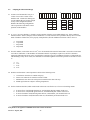
1
STUDY GUIDE FOR PHOTOVOLTAIC SYSTEM INSTALLERS AND SAMPLE EXAMINATION QUESTIONS PREPARED FOR: U.S. DEPARTMENT OF ENERGY AND SANDIA NATIONAL LABORATORIES REVISION FOR THE SEPTEMBER 24, 2005 PV INSTALLER CERTIFICATION EXAM FOR THE NORTH AMERICAN BOARD OF CERTIFIED ENERGY PRACTITIONERS NABCEP HTTP://WWW.NABCEP.ORG/ TABLE OF CONTENTS 1. INTRODUCTION ........................................................................................................................................................ 1 2. REFERENCE RESOURCES AND ADDITIONAL READING MATERIALS ..................................................... 3 2.1 2.2 3. REFERENCES: ......................................................................................................................................................... 3 ADDITIONAL READING MATERIAL:........................................................................................................................ 3 PHOTOVOLTAIC (PV) INSTALLER STUDY GUIDE .......................................................................................... 4 3.1 WORKING SAFELY WITH PHOTOVOLTAIC (PV) SYSTEMS (TASKS 1.1 THRU 1.9 OF THE NABCEP TASK ANALYSIS) 4 3.1.1 OSHA Regulations............................................................................................................................................ 4 3.1.2 Safety in Attics .................................................................................................................................................. 5 3.1.3 Working Space for Electrical Systems.............................................................................................................. 5 3.1.4 How Photovoltaic Systems Work, and Associated Safety and Testing Issues................................................... 6 3.2 CONDUCTING A SITE ASSESSMENT (TASKS 2.1 THRU 2.10 OF THE NABCEP TASK ANALYSIS)........................... 10 3.2.1 Shading........................................................................................................................................................... 10 3.2.2 Array Orientation ........................................................................................................................................... 13 3.2.3 Array Location ............................................................................................................................................... 13 3.2.4 Array Mounting Methods................................................................................................................................ 15 3.2.5 BOS Locations .................................................................................................................................................... 15 3.3 SELECTING A SYSTEM DESIGN (TASKS 3.1 THRU 3.4 OF THE NABCEP TASK ANALYSIS) ................................... 15 3.4 ADAPTING THE MECHANICAL DESIGN (TASKS 4.1 AND 4.2 OF THE NABCEP TASK ANALYSIS) ......................... 16 3.5 ADAPTING THE ELECTRICAL DESIGN (TASKS 5.1 THRU 5.8 OF THE NABCEP TASK ANALYSIS) ......................... 19 3.5.1 Wire, Fuse, Circuit Breaker, and Disconnect Sizing ...................................................................................... 20 3.5.1.1 Temperature and Conduit Fill Corrections for Ampacity of Conductors ......................................................... 20 3.5.1.2 Voltage Drop for Circuits .............................................................................................................................. 21 3.5.2 Charge Controllers and Linear Current Boosters.......................................................................................... 24 3.5.3 Batteries and Battery Wiring.......................................................................................................................... 27 3.5.4 Inverters.......................................................................................................................................................... 27 3.5.5 Point-of-Utility Connection ............................................................................................................................ 31 3.5.6 Optional Standby System Panels .................................................................................................................... 32 3.5.7 Grounding ...................................................................................................................................................... 32 3.5.8 Generators...................................................................................................................................................... 33 3.6 INSTALLING SUBSYSTEMS AND COMPONENTS AT THE SITE (TASKS 6.1 THRU 6.10 OF THE NABCEP TASK ANALYSIS) ......................................................................................................................................................................... 34 3.7 PERFORMING A SYSTEM CHECKOUT AND INSPECTION (TASKS 7.1 THRU 7.8 OF THE NABCEP TASK ANALYSIS) 37 3.8 MAINTAINING AND TROUBLESHOOTING A SYSTEM (TASKS 8.1 THRU 8.7 OF THE NABCEP TASK ANALYSIS).... 40 4. STUDY GUIDE REVIEW QUESTIONS ................................................................................................................. 42 4.1 4.2 4.3 4.4 4.5 4.6 4.7 4.8 WORKING SAFELY WITH PHOTOVOLTAIC SYSTEMS ............................................................................................. 42 CONDUCTING A SITE ASSESSMENT ...................................................................................................................... 43 SELECTING A SYSTEM DESIGN ............................................................................................................................. 45 ADAPTING THE MECHANICAL DESIGN ................................................................................................................. 46 ADAPTING THE ELECTRICAL DESIGN ................................................................................................................... 47 INSTALLING SYSTEMS AND SUBSYSTEMS AT THE SITE ......................................................................................... 52 PERFORMING A SYSTEM CHECKOUT AND INSPECTION ......................................................................................... 53 MAINTAINING AND TROUBLESHOOTING A SYSTEM.............................................................................................. 54 5. ANSWER KEY TO STUDY GUIDE REVIEW QUESTIONS .............................................................................. 56 6. APPENDIX.................................................................................................................................................................. 61 6.1 IRRADIATION (FORMERLY CALLED INSOLATION) DATA FOR DENVER, CO .......................................................... 61 Disclaimer Information presented in this publication is intended to inform candidates as they prepare to apply for and complete the certification process ™ for the Certified Solar Photovoltaic Installer Certification Program. While NABCEP has made a reasonable effort to provide current and accurate information, neither NABCEP, nor its employees, volunteers, or representatives warrants or guarantees the accuracy, completeness, timeliness, merchantability, or fitness of the information contained herein for a particular purpose. Reference herein to any specific commercial product, process, training program, or service by trade name, trademark, manufacturer, or otherwise does not constitute or imply its endorsement, affiliation, or support by NABCEP or other contributors to this document. While individuals certified as a Certified ™ Solar Photovoltaic Installer are required to meet established certification requirements, NABCEP maintains no control over these certificants or their related organizations, and disclaims all liability to any party for any action or decision made in reliance on the information contained herein or otherwise provided by NABCEP, or for any actions or inactions of candidates or certificants to any party, or for any loss or injury, resulting from the use or non-use of such information. 1. Introduction This Study Guide presents some of the basic cognitive material that individuals who install and maintain photovoltaic (PV) power systems should know and understand. This information is intended primarily as a Study Guide to help individuals better prepare for the NABCEP PV installer examination but does not provide all of the materials needed for completing the certification examination. Knowledge of the information presented, knowledge of pertinent sections of the National Electrical Code and appropriate experience and qualifications are generally required of those applying for and completing the NABCEP certification process. Applicants and certificants are also reminded that local installation codes can differ from national codes and the information presented in this Guide. This Guide is based on a task analysis for the PV system installer, which includes the following eight major job/task areas: 1. 2. 3. 4. 5. 6. 7. 8. Working Safely with Photovoltaic Systems Conducting a Site Assessment Selecting a System Design Adapting the Mechanical Design Adapting the Electrical Design Installing Subsystems and Components at the Site Performing a System Checkout and Inspection Maintaining and Troubleshooting a System 15% 5% 5% 15% 20% 20% 10% 10% The percentage following each task area represents the approximate emphasis that each topic is given in this Guide, and is similar to what would be expected for a typical distribution of emphasis in training programs and on formal testing for certification and/or licensure in the trade. How this Guide is used may depend upon how much the reader already knows about installing PV systems. This Guide is organized in the following manner: • • • • Reference Resources and Additional Reading Study Guide Sample Examination Questions Answer Key The Guide is intended to provide an overview of each of the major content areas of the above task analysis. A set of practice questions that relate to each of the major content areas is then provided. The questions are organized according to each content area. The answers to the practice questions, along with related explanations, are given at the end of this Guide. The experienced installer may wish to try the questions first. Then, if any are missed, s/he can study the answer key to review the methods for solving the problems used by the technical experts who provided input to the authors of this Guide. Individuals that are new to these topics likely will benefit most from starting at the beginning of the material and working through to the end, answering questions after completing each section, but this Guide alone will neither ensure the applicant will meet the requirements for taking the exam nor provide enough code-related information to successfully complete the exam. The sample examination questions span fundamental trade knowledge, codes and standards, and accepted industry practice in the relevant design, installation, and maintenance of PV systems. Many questions are based on system installation scenarios, requiring the use of schematics, diagrams, and equipment specifications. Guidelines for determining solutions to the questions may be found in the text of this Guide, or from the references listed below. The suggested reading materials are also listed to broaden resources for the applicant but have not been validated by legal entities or checked for accuracy by NABCEP. In addition to the specific content areas listed above, knowledge and skills in the following content areas are required for successful completion of the examination: 1 Study Guide for the Applicant for NABCEP Photovoltaic Installer Certification Version 3 – August, 2005 1 • • • Reading and interpreting plans and specifications Reading and interpreting codes and standards Using basic mathematics and some trigonometry (addition, subtraction, multiplication, division, calculations of area and volume, fractions, decimals, percentages, calculating the sides of triangles, square roots, powers of numbers, and solving simple algebraic equations for unknown variables) One does not need to understand algebra or calculus to be able to engage in safe work practices around PV systems, but it is useful to better understand how PV systems work, to understand how to calculate expected system performance, and to evaluate the results of the system operation. Study Guide for the Applicant for NABCEP Photovoltaic Installer Certification Version 3 – August, 2005 2 2. Reference Resources and Additional Reading Materials 2.1 References: The following reference list identifies training materials, reports, and codes and standards associated with the design and installation of PV systems and are complementary to this Guide. Many of the sample questions come from these references, as does other content in this Guide. Perhaps the most important reference on this list is the 2005 National Electrical Code (NEC), or its expanded 2005 National Electrical Code Handbook, and as so much of the material in this Guide is based on the NEC, it is strongly encouraged that a copy be kept close at hand while reviewing this document. 1. 2001 Code of Federal Regulations, Chapter 29 Part 1926 - Safety and Health Regulations for Construction. U.S. Department of Labor/OSHA, OSHA Publications, P.O. Box 37535, Washington, D.C. 20013-7535 http://www.osha.gov 2. 2005 National Electrical Code®, NFPA 70, National Fire Protection Association, 1 Batterymarch Park, Quincy, MA 02269 (or 2005 National Electrical Code Handbook) http://www.nfpa.org/nec/ 2.2 Additional Reading Material: 1. Objectives and Task Analysis for the Solar Photovoltaic System Installer, North American Board of Certified Energy Practitioners Technical Committee Document, Approved 6/4/2002, http://www.nabcep.org/pdf/resources/SolarPVTaskAnalysis.pdf 2. Photovoltaic Power Systems and the 2005 National Electrical Code: Suggested Practices, SAND2005-0342, February 2005, Sandia National Laboratories, Photovoltaic Systems Assistance Center, Albuquerque, NM 871850753 http://www.sandia.gov/pv. Also available in PDF format only from the Southwest Technology Development Institute, http://www.nmsu.edu/%7Etdi/Photovoltaics/Codes-Stds/PVnecSugPract.html 3. A Guide to Photovoltaic System Design and Installation, California Energy Commission Consultant Report 50001-020, June 2001 http://www.energy.ca.gov/reports/2001-09-04_500-01-020.PDF 4. Battery Service Manual, 11th Edition, Battery Council International, 401 North Michigan Avenue, Chicago, IL, 60611 http://www.batterycouncil.org/publications.html 5. Installing Photovoltaic Systems (Course Manual), 2002, Florida Solar Energy Center, 1679 Clearlake Road, Cocoa, FL 32922-5703 http://www.fsec.ucf.edu 6. Working Safely with Photovoltaic Systems, January 1999. Sandia National Laboratories, Photovoltaic Systems Assistance Center, Albuquerque, NM 87185-0753 http://www.sandia.gov/pv 7. Maintenance and Operation of Stand-Alone Photovoltaic Systems, December 1991. Sandia National Laboratories, Photovoltaic Systems Assistance Center, Albuquerque, NM 87185-0753 http://www.sandia.gov/pv 8. Stand-Alone Photovoltaic Systems: A Handbook of Recommended Design Practices, SAND87-7023. Sandia National Laboratories, Photovoltaic Systems Assistance Center, Albuquerque, NM 87185-0753 http://www.sandia.gov/pv 9. Hybrid Power Systems: Issues and Answers. Sandia National Laboratories, Photovoltaic Systems Assistance Center, Albuquerque, NM 87185-0753 http://www.sandia.gov/pv 10. The NRCA Roofing and Waterproofing Manual, 5th Edition, National Roofing Contractor’s Association, http://shop.nrca.net/pubstore/manual.asp?ProductID=243 11. Home Power: The Hands-on Journal of Home-Made Power, Home Power, Inc., PO Box 520, Ashland, Oregon, www.homepower.com Study Guide for the Applicant for NABCEP Photovoltaic Installer Certification Version 3 – August, 2005 3 3. Photovoltaic (PV) Installer Study Guide 3.1 Working Safely with Photovoltaic (PV) Systems (Tasks 1.1 thru 1.9 of the NABCEP Task Analysis) Working safely with PV systems requires a fundamental understanding of electrical systems coupled with common sense. The common sense aspects can be summed up with the following statements: • • • • If the workplace is cluttered, the possibility of tripping over something is significantly increased. If the workplace is a sloped roof with clutter, the possibility of falling off the roof is significantly increased. If tools are left lying out on a roof, the chance of them falling off the roof and injuring someone below is increased. If the workplace is a rooftop in bright sunshine, the chance of sunburn is increased, so a good layer of sunscreen is in order. There are the usual subtle hazards, as well. These include nicks, cuts, and burns from sharp or hot components. Gloves should be used when handling anything that might be sharp, hot, rough, or that might splinter. There is always the possibility of dropping tools or materials on either oneself, someone else, or on sensitive equipment or materials. Dropping tools across battery terminals is an especially dangerous hazard. When a PV system is being assembled, it presents the possibility of shock to personnel. Improperly installed systems may result in fire should an electrical short circuit occur. The surprise elements on the job site cannot be overlooked. There is nothing more disconcerting when trying to move to a new position on a roof, only to bump into someone who has quietly moved into the space that you had hoped to occupy. It can cause a loss of balance and result in a serious fall. When working in a potentially dangerous location, it is wise to keep a conversation going so workers know exactly where everyone is located. 3.1.1 OSHA Regulations All PV installers should be familiar with construction standards established by The Occupational Safety and Health Administration (OSHA), which are covered in Chapter 29 of the U.S. Code of Federal Regulations, Part 1926, Safety and Health Regulations for Construction. Part 1926 consists of 26 subparts, labeled from A to Z. All parts are important, but some parts, such as underwater construction, refer to situations that will not be encountered with typical PV installations. The OSHA rules most relevant to PV installations include Subpart D − Occupational Health and Environmental Controls Subpart E – Personal Protective and Life Saving Equipment Subpart I – Tools, Hand, and Power Subpart K – Electrical Subpart X – Stairways and Ladders Several especially pertinent issues relating to PV installations include the following: • • • • • No construction worker will be required to perform work under conditions that are unsanitary, hazardous, or dangerous to his safety or health. 1926.10(a) The employer shall initiate and maintain a job site safety and health program. 1926.20(b)(1) The use of any machinery, tool, material, or equipment that is not in compliance with safety standards is prohibited. 1926.20(b)(3) Every employee shall be instructed in the recognition and avoidance of unsafe conditions. 1926.21(b)(2) Every employee shall be instructed in the safety and health regulations applicable to his/her work. 1926.21(b)(2) Falls are the leading cause of workplace fatalities, with 150–200 workers killed each year and nearly 10,000 injured. Because nearly every PV system involves climbing on a ladder, onto a roof, or both, it is essential that PV installers be familiar with OSHA fall protection regulations. OSHA requires that fall protection must be provided where needed. Any work done at more than six (6) feet above ground level must be done with fall protection considerations. Fall protection systems may include safety net systems, warning line systems, covers, toe boards, safety harnesses, or lanyards. Study Guide for the Applicant for NABCEP Photovoltaic Installer Certification Version 3 – August, 2005 4 In cases where no specific fall protection system is used, OSHA allows a safety monitoring system in which a person can oversee the operation provided that the person is • • • • • Competent in recognition of fall hazards, Capable of warning other workers, Operating at the same level as the other workers where the other workers can be seen by the monitor, Close enough to the operations to communicate orally, and Having no other distracting duties. Even when care is taken to ensure that no person falls, it is equally important to ensure that no tool or part is dropped. If the object is dropped from overhead, anyone below is subject to having the object fall on him or her. Furthermore, there may be scaffolds, lumber, or any number of other items on a job site capable of inflicting head or other bodily injury. For this reason, it is important to review Subpart E, where OSHA specifies foot protection, head protection, eye protection, face protection, and respiratory protection, in addition to fall protection practices. 3.1.2 Safety in Attics Some PV installations may involve working in attic spaces. Working in an attic generally will require wearing a breathing mask, eye protection, clothing that will protect skin from insulation, and will require knowledge of where it is safe to support the weight of a person without risk of falling through the ceiling. It will also involve planning the excursion into the attic to ensure that it will also be possible to get out of the attic. And adequate lighting will be needed in the confines of the attic. Before entering an attic, one should be sure to drink water for hydration if the attic is hot and if it is expected that the attic work will take more than 15 minutes. It is essential when traversing an attic to support one’s weight by stepping only on the ceiling joists or trusses. There may be 1x2” furring strips for holding rock lath or plaster board, but these will not support the full weight of a worker. They may be confused with joists or trusses when they are covered with insulation. The ceiling material itself will definitely not support the weight of a worker. In many cases, planking or boards may be placed above joists temporarily to support the weight of workers in attics, making it easier to work. Care should be taken not to drop or lay heavy tools onto the ceiling material. It may crack the ceiling. Also, care should be exercized when climbing around wires, piping, air conditioning ductwork, and any other attic protrusions, such as recessed lighting fixtures. The recessed fixtures may be hot, and the other items are subject to damage if they are overstressed. Furthermore, wires, pipes, etc., present a tripping or choking hazard to the worker. Special care must be made to avoid crushing air conditioning ductwork or existing electrical wiring. Caution is essential where protruding roofing nails may catch on clothing or cause lacerations and punctures to the worker. 3.1.3 Working Space for Electrical Systems The National Electrical Code is very specific on the working spaces that must be accommodated for maintenance personnel to operate on equipment safely. Article 110.26 covers the requirements relative to working spaces. Rather than restate all the requirements in 110.26, this guide is highlighting the fact that knowing the requirements for proper working spaces is essential to preserve the safety and accessibility of an electrical working space. Proper working clearances are the first priority when locating balance of system hardware for a PV system. Generally, clearances are 3 feet, but several qualifiers determine the appropriate clearance to use. Voltages from 150-600V require greater clearances if live parts are on one side and grounded parts on the other or if live parts are on both sides of the working space. The width of working spaces must be the width of the equipment or 30 inches, whichever is wider. For dc voltages less than 60 V, smaller working spaces may be permitted by special permission of the AHJ. Although this is allowed in the code, permission must be secured prior to mounting equipment should smaller clearances be sought. Study Guide for the Applicant for NABCEP Photovoltaic Installer Certification Version 3 – August, 2005 5 3.1.4 How Photovoltaic Systems Work, and Associated Safety and Testing Issues Both the modules and inverters in PV systems are subject to UL standards, however this only provides a measure of safety of the device and does not indicate field performance or reliability. There are relatively few resources to find comprehensive and unbiased analyses on field performance of these products. And even so, a given product may perform quite well in one set of conditions but under-perform in other conditions (e.g. at given temperatures, voltages, etc.). Also, manufacturer specifications are listed in a laboratory and it is important to recognize that field performance is far more dynamic than what is seen on a specification sheet. For modules, the tolerance of the manufacturing processes (i.e. modules rated as a given number of Watts +/- X%) is one key parameter. Likewise, the performance in the temperature conditions expected at your site will be relevant. Modules also achieve a lower performance due to voltage degradation over time, so understanding the stability of the products is valuable in determining the long-term system output. Meanwhile, system designers should also consider other issues like how well modules endure various environmental effects. Inverters are also complex components. Inverter performance and reliability is important to good system design, since it enhances or limits the effectiveness of a given system. Inverters have many more variables than modules. Although DCAC conversion efficiency is often the primary factor looked at to determine system performance, this alone is incomplete and can be misleading since this efficiency changes with DC input voltage, AC output voltage, percentage of load, and several other factors. The output of a system is also dictated by its maximum power point tracking effectiveness, its ability to output high power at the site's expected temperature, and product reliability. The most critical objective of any inverter is to output kWh throughout the life of the system. Choices should typically be based around this principle, and then the other features of the products. Warranties, manufacturer reputability, and ease of installation/use are also worth considering for both modules and inverters. As with any other type of products, there are a wide array of manufacturers offering a range of performance, reliability and features. Discussions with other experienced installers is often the most effective way of determining a product's true value in the field. For example, some modules may be rated within +/- 5%, but often perform at the lower end of this tolerance while others with the same tolerance may regularly achieve their output target, or even above. Some inverters offer sophisticated self-diagnostic systems to assist installers in servicing systems or data monitoring systems that allow installers or end-users to view performance more easily over a computer. Though looking at specification sheets and product literature is often a good place to begin your search for choosing the appropriate components for a system, it is best to get input from experienced users on the products you may specify prior to installing them. 3.1.4.1 Photovoltaic Modules Photovoltaic modules generate electricity as a result of sunlight shining on the PV cells, and these cells may be made of any of several technologies. Some of these technologies used in flat-plate modules (as opposed to concentrator modules) include crystalline silicon cells, multi-crystalline silicon cells, thin-film amorphous silicon cells deposited on a substrate, thin-film cadmium-telluride (CdTe) cells deposited on glass or other suitable substrate, thin-film copper-indium-diselenide (sometimes referred to as CIS) deposited on glass or other suitable substrate, or other technologies now being developed. Using crystalline technology for example, where individual cells produce dc voltages of approximately 0.5 volt and dc currents in the range of one to eight amps (with the amperage depending on the surface area of the cell) takes a large number of cells to produce appreciable amounts of voltage and power. Usually, PV cells are grouped into series strings of 36 or 72 cells to produce open-circuit voltages of approximately 20 or 40 V, though these configurations change with manufacturing trends. A 120-watt PV module made of crystalline silicon PV cells encapsulated between layers of glass, antireflective coating, and an encapsulant material in an aluminum frame will typically have an area of about 10 ft2, and will weigh about 30 pounds. Each year, however, sizes of PV modules have been increasing. During the decade of the 1990s, most modules produced were in the 35 to 75 watt range, while modules are now common in the 100-200 watt range, with some producing as much as 300 watts and weighing more than 100 pounds. Study Guide for the Applicant for NABCEP Photovoltaic Installer Certification Version 3 – August, 2005 6 Other technologies require multiple cells in series and parallel, resulting in different voltage and current characteristics for the modules. Temperature coefficients for voltage and current output as well as conversion efficiencies differ for each technology. Photovoltaic module performance is characterized by its open circuit voltage (Voc), short circuit current (Isc), maximum power voltage (Vmp), and maximum power current (Imp). Figure 1 shows a typical relationship between module current and module voltage for different levels of sunlight (irradiance) incident on a PV module. Sunlight intensity is called Irradiance, which is measured in watts per square meter (W/m2). In summer, when the sun is nearly directly overhead, its irradiance at the surface of the Earth, at sea level, is approximately 1000 W/m2. This irradiance is defined as “full” or “peak sun,” and it is the standard irradiance for testing and rating PV modules. At peak sun conditions, roughly 70% of the sun that is incident at the top of the atmosphere penetrates to the surface of the Earth. If PV modules are mounted perpendicular to the sun’s rays, it is possible to receive close to peak sun nearly every sunny day at noon for much of the continental United States. However, at different times of the year, and at higher elevations, sunlight intensity can be as much as 1250 W/m2 or more for hours at a time. As the sun moves to a lower position in the sky, solar radiation passes through more of the Earth’s atmosphere, resulting in more of the irradiance being absorbed. Note also that the output of the PV module is also affected by the spectrum of the incident light reaching the module. The spectrum of light from the sun changes based on how much atmosphere the light travels through. Photovoltaic module testing uses the spectrum of light produced when the sun shines through the equivalent air mass of 1.5 times the atmosphere thickness at the equator as a standard so that all modules are evaluated under the same conditions. This is the amount of atmosphere sunlight travels through to get to the Earth on March 21 at solar noon at Cape Canaveral, Florida. This is referred to as Air Mass 1.5 in testing specifications. As shown in Figure 1, the current generated by a module is directly proportional to the irradiance incident on the module. If the sunlight strikes a module at an angle, the effective irradiance on the module is reduced and the module current decreases. Thus, if modules are mounted so they always face the sun, they will generate the maximum possible current for that level of irradiance. In areas that have minimal cloud cover and long daylight hours, array mounts that track the sun can increase the daily energy from a PV module by as much as 40% in summer months. In cloudy areas, the enhancement from a tracking array is less. Figure 1 also shows that the current produced by a module is limited even when it is shorted (V=0). Shorting a PV module generally does not damage it; however, there are exceptions. In fact, measuring the short-circuit current of a module when it is disconnected from the rest of the system is one way to test for good or bad modules. Some PV charge controllers regulate battery charging by short-circuiting the module or array. Note that short circuits for extended periods of time (greater than several minutes under high irradiance) may damage some thin-film modules. Manufacturers’ data sheets provide applicable cautions. The open-circuit voltage of a module occurs when the module is not supplying any current (when the module is disconnected from all loads). Note from Figure 1 that the open-circuit voltage of a module is minimally dependent on irradiance. If modules are connected in series, then the module voltages add, just as in the case of batteries. So if higher voltages are needed, then modules are connected in series until the desired voltage is reached. If modules are connected in parallel, then the module currents add just as in the case of batteries. If higher currents are needed, then modules are connected in parallel until the desired current is reached. Most PV arrays consist of series−parallel arrangements of modules to achieve the desired operating voltage and current. Study Guide for the Applicant for NABCEP Photovoltaic Installer Certification Version 3 – August, 2005 7 6.0 A Imp 4.5 2 4.5 3.0 o 0C o 25 C o 50 C 250 W/m 1.5 2 o 500 W/m 3.0 Module c urrent, A 750 W/m 2 75 C Module current, A 6.0 1000 W/m 2 1.5 Vmp 0 0 4 8 12 16 Module voltage, V 20 24 Figure 1. Dependence of current and voltage on incident sunlight levels. 0 0 4 8 16 12 Module voltage, V 20 24 Figure 2. Dependence of current and voltage on temperature for sunlight level of 1000 W/m2. The maximum power voltage and maximum power current are the module voltage and current levels for which the module delivers the maximum possible power for a given irradiance level. For each irradiance level, there is only one voltage and one current at which maximum power output occurs, as illustrated by point A in Figure 1. Many inverters and some charge controllers that are used with PV arrays are designed to electronically track the maximum power point (MPP) of the array and thus deliver maximum power to the batteries or loads. A PV module or PV array may exhibit more than one point where the power curve may have extra peaks, and these may be interpreted by some maximum power trackers as the maximum power point. This typically occurs when one or more modules in an array are shaded or not operating properly causing bypass diodes to conduct. The current and voltage available from a PV module are temperature-dependent. The voltage is much more temperaturedependent than is the current for crystalline silicon-based modules. For crystalline silicon modules, as the module temperature increases, the module current only increases slightly while the module maximum power voltage (Vmp) decreases by approximately 0.5% per °C, resulting in a maximum power decrease of approximately 0.5% per °C. as shown in Figure 2. Conversely, as the temperature of the module decreases, the voltage and power increase by approximately 0.5% per °C. Thus, crystalline silicon-based PV modules achieve their highest voltages at the lowest temperatures. Table 690.7 of the 2005 National Electrical Code gives voltage correction factors for crystalline silicon PV modules that are operated at low temperatures. Note that the PV array open-circuit voltage at the lowest temperature is the maximum system voltage as defined by the NEC. Note also that PV modules using other than crystalline silicon may exhibit significantly different temperature characteristics. The manufacturer for thin-film PV modules provides the module relationships to irradiance and temperature. Because the electrical characteristics of PV modules vary with irradiance and temperature, the nameplate on the back of a module lists the electrical properties of the module under Standard Test Conditions (STC). Standard Test Conditions are a cell (module) temperature of 25°C, an Air Mass of 1.5, and under an irradiance level of 1000 W/m2. These conditions are conducive to testing in a manufacturing environment but tend to overestimate actual performance, as the cell temperature is rarely at a temperature of 25°C and an irradiance of 1000 W/m2 at the same time. An operating cell temperature of 50°C is much more common when the module is at mild ambient temperatures. For crystalline modules that lose 0.5% per °C, this corresponds to a typical performance that is 12% below the value tested under STC ((50°C-25°C) x 0.5% /°C = 12.5%). Working safely with PV modules involves taking precautions to avoid electrical shock from potentially high dc voltages, especially when several modules are connected in series. It also involves care in handling of the modules so they are not dropped and care in protecting open wire ends from shorting to each other. Because a short circuit may not blow any fuses, opening the short circuit produces a very intense dc arc between the wires. Once initiated, this arc can reach temperatures of 10,000°C over a distance of half an inch or more. This arc is a potential fire hazard, burn hazard, ultraviolet eye hazard, or might surprise the electrical worker causing him/her to lose footing, creating a fall hazard. Study Guide for the Applicant for NABCEP Photovoltaic Installer Certification Version 3 – August, 2005 8 The National Electrical Code, in Article 690.5, requires that any PV array installed on the roof of a dwelling must incorporate a ground-fault protection device to reduce fire hazards. The device “shall be capable of detecting a ground fault, interrupting the flow of fault current, and providing an indication of the fault.” Note that the purpose of this dc ground-fault protection device differs from that of the ac ground fault-circuit interrupter (GFCI) in that the GFCI is intended for prevention of serious shock, while the ground-fault protection is intended to detect and interrupt higher currents that can create a fire hazard. 3.1.4.2 Battery Safety Some PV systems are designed to provide power to loads even when the sun is not shining, and these typically use battery storage. Batteries used in PV systems are normally lead-acid batteries of the deep discharge type. Occasionally nickelcadmium, nickel-iron, or nickel-metal-hydride batteries are used. Deep discharge-type batteries differ from automobile starting batteries; deep discharge units are designed with heavier, thicker plates for better deep discharge performance. Automobile starting batteries have a larger number of thin plates to provide a greater plate surface area so it can provide high starting currents for short times. If an automobile battery is used in a PV system, it will generally degrade much faster because it is not designed for deep cycling. Electric golf cart batteries are one type of relatively inexpensive deep-cycle battery that is often used for energy storage in smaller PV systems. Lead-acid storage batteries come in sealed and vented designs, and each has different charging and discharging characteristics. The charge controllers must compensate for these differences through the charge controller settings. Sealed units are more expensive, but require less maintenance. Vented batteries are less expensive, but require more maintenance. The level of electrolyte needs to be checked periodically, and distilled water needs to be added when it is low. Furthermore, vented batteries release more hydrogen and oxygen along with other corrosive gases, even under normal operating conditions. Because hydrogen is lighter than air, it tends to accumulate at the top of the battery container, and if the hydrogen concentration gets too high, the mixture becomes explosive. Therefore, battery containers should be vented at the top to allow the hydrogen to escape. NEC 480.9(A) states that all battery locations must provide ventilation, but it does not provide any guidance for that ventilation. Normally the containers will not be vented at the bottom because acid containment is another requirement. NOTE: Hydrogen venting is quite different than providing combustion air for appliances. When vented lead-acid batteries are used, they should not be located beneath any electronic components. The corrosive vapors from the batteries can degrade the circuitry in the electronic equipment causing premature failures. Batteries should always be placed in an enclosure that can safely contain the entire battery electrolyte released in the event of a spill or case breakage. When using lead-acid batteries, it is good practice to have baking soda nearby, preferably a supply in the battery container so it is readily available to neutralize the acidic battery electrolyte in the event of a spill. If nickel-cadmium batteries are used, the electrolyte is a strong base, so vinegar (acetic acid) should be kept near the batteries to neutralize any spill of the electrolyte. Eye, face, and hand protection should be used when working near batteries, and an apron may be used to protect clothing. Because of the danger of working with batteries, it is important to allow adequate working clearances for battery maintenance. Working clearances shall comply with NEC 110.26 as stated in NEC 480.9 (C). It is especially important to use insulated tools to prevent battery shorts when working around batteries. If battery terminals are shorted, currents greater than 10,000 A may flow through the short circuit, resulting in damage to the tool, explosion of the battery, and serious injury to the worker. Because such high currents can flow, the battery overcurrent protection must have an interrupting rating sufficient to interrupt the battery short-circuit current. Battery circuits should nearly always be equipped with charge controllers for overcharge protection. If a battery is overcharged, its life is generally reduced. Furthermore, severe overcharging may cause a dangerous pressure build-up in sealed units and will cause vented units to release gases at a much higher rate. The gases come from the electrolysis of the electrolyte, which also causes the electrolyte level to decrease. If the level drops below the top of the lead plates, the tops Study Guide for the Applicant for NABCEP Photovoltaic Installer Certification Version 3 – August, 2005 9 of the plates will be degraded. If a lead-acid battery is over-discharged, its lifetime is also significantly decreased. Some systems include overdischarge protection to prevent battery damage resulting from prolonged discharge. The NEC requires that if the total (nominal) voltage of a battery bank exceeds 48 V, then the batteries shall not be installed in conductive cases. The term nominal is used in the NEC and assumes 2 volts per cell for lead-acid batteries. Note that 48-V nominal battery banks exceed the 50-V limit for allowed ungrounded PV systems in NEC 690.41. This mix of terminology is often confusing and requires a thorough understanding for interpreting the NEC. If the batteries are mounted on metal racks, the metal of the rack must not come closer than six (6) inches to the battery terminals. The exception to this rule is for Valve-Regulated Lead-Acid (VLRA) batteries or sealed units that use steel cases. NEC 690.71(D-G) requirements state that if batteries are connected in series to produce more than 48 V (nominal), then the batteries must be connected in a manner that allows the series strings of batteries to be separated into strings of 48 V or less for maintenance purposes. The means of disconnect may be non–load-break, bolted, or plug-in disconnects. For strings in excess of 48 V, there must also be a means of disconnecting the grounded circuit conductors of all strings under maintenance without disconnecting the grounded conductors of operational strings. If batteries are used outdoors in cold climates, the electrolyte freezing temperature increases as the batteries discharge. If the electrolyte freezes, DO NOT CHARGE THE BATTERY. Let it thaw slowly in a place where, if it should rupture, the electrolyte will be contained. Do not attempt to accelerate the thawing process with anything that might be capable of igniting any gases that may be liberated. 3.2 Conducting a Site Assessment (Tasks 2.1 thru 2.10 of the NABCEP Task Analysis) A PV installer needs to know how to determine whether a proposed site for a PV installation will be adequate for proper operation of the system. A site assessment involves • • • • • 3.2.1 Determining whether the array can operate without being shaded during critical times, Determining the location of the array, Determining the mounting method for the array, Determining where the Balance-of-system (BOS) components will be located, and Determining how the PV system will interface with the existing electrical system. Shading A site assessment involves determining whether the location of the PV array will be shaded, especially between the hours of 9 a.m. and 3 p.m. solar time. This is important, as the output of PV modules may be significantly impaired by even a small amount of shading on the array. Crystalline silicon module outputs are generally more susceptible to shading than thin-film module outputs, because the thin-film cell structure traverses the full length of the module requiring more shading for the same effect. For maximizing benefits to utility companies in some utility-interactive PV installations it may be desirable for the array to face either southwest or even west, provided that the array tilt is below 45º.. Westerly orientations tend to maximize the array output in the afternoon during utility peak usage hours, but do not necessarily maximize the benefit to the customer. Some net metering programs offer time-differentiate rate structures to encourage the production of energy during utility peak hours. A careful assessment using an hourly computer simulation program is necessary to determine the benefits of westerly orientations. A minimum of six hours of unshaded operation is still important for best system performance. There are formulas that enable the system designer to calculate the position of the sun at any time of the day, any day of the year, at any place on the planet. While an installer is not expected to know how to use these formulas, the installer should know that devices are available for observing the path of the sun at a location for each month of the year. These devices can be used to determine whether any obstructions in the vicinity of the array will shade the array during critical sun times at any time during the year. A Solar Pathfinder (www.solarpathfinder.com) or similar device can be used effectively to estimate the impact of shading at any location. Study Guide for the Applicant for NABCEP Photovoltaic Installer Certification Version 3 – August, 2005 10 The location of the sun in terms of North, East, West, or South is determined by the azimuth angle, usually symbolized by the Greek letter Psi (ψ). When a conventional compass is used, North is 0° or 360°, East is 90°, South is 180° and West is 270°. But for calculating sun paths, due South is often used as the zero degree reference, as the sun is due South at solar noon. Note that solar noon is not necessarily the same as 12 p.m. clock time due to various offsets including daylight savings time. A simple method to determine solar noon is to find the sunrise and sunset times in a local paper and calculate the midpoint between the two. In summary, for solar calculations, 0° typically represents true South, 90° represents East, 180° represents North, and 270° or -90° represents West. Azimuth angles west of south are typically represented as negative angles and azimuth angles east of south are conversely represented as positive angles. The location of the sun in terms of the angle between the sun and the horizon, where horizon is defined at the plane tangent to the Earth’s surface at the point of measurement, is determined by the altitude angle, and symbolized by the Greek letter alpha (α). At sunrise and at sunset, when the sun is on the horizon, the altitude is 0°. If the sun is directly overhead, then ψ the altitude is 90°. The sun will be directly overhead only in the tropics located between the Tropic of Cancer and Tropic of S Capricorn (23.45° north and south of the equator, respectively). When the sun is up, it is at an altitude angle between 0° and 90°. ψ It is interesting to note that everywhere on the Earth, on the first day of spring and on the first day of fall (equinoxes), the sun Top view rises directly in the east and sets directly in the west and is above the horizon for exactly 12 hours. 1 2 Knowledge of the azimuth and altitude of the sun at any particular date and time will enable the determination of whether the array will be shaded, but it is very difficult to quantify the effects of shading due to the variables involved (degree of shading, placement of shading, series/parallel connection of cells and modules, etc.). Devices can be purchased that allow the user to view potential shading problems and quantify the impact of the shading and provide a reasonable energy loss estimate. Although understanding the sun’s position using azimuth and altitude is important, calculating the impact of shading is even more important. (level) α Side view Figure 4. Tree shading example Figure 3. Tree Shading Example For example, suppose a tree is located as shown in Figure 3. Suppose also that one wishes to determine whether the tree will shade the array during critical times at any time of the year. Because the south row of PV modules is closer to the tree, and it is also lower in height, it is most susceptible to shading problems. Therefore, if the bottom row of modules is not shaded, then the top row will not be shaded from the same obstruction. The critical points to observe are the two bottom corners of the array where the sun’s lower elevation combined with the azimuth angle can result in a shadow. Remember that some trees may grow a foot or more per year, both in height and width, so understanding growth rates and the ultimate size of a tree is also important when estimating the shading impact from trees. Notice next that the westernmost corner (the one closest to the tree) will be shaded first and most likely in the afternoon, as the position of the sun moves east to west. Before solar noon, as the sun moves toward the west, the altitude increases until the sun appears due south. As the sun moves farther to the west, its altitude decreases. The altitude and the azimuth must both be considered. In this example, the array may be shaded for a short time in the morning then be fully illuminated around solar noon and then be shaded later in the day as the sun’s altitude decreases. Inter-row shading refers to the situation where one row of modules shades an adjacent row of modules. A six-inch shadow from an adjacent module is capable of shutting down a whole section of modules and can even shut down the entire PV system down. A simple rule for minimum spacing between rows is to allow a space equal to three times the height of the top of the adjacent module. The example in Figure 4 suggests that a separation distance (d) should be nine feet since the height of the adjacent row is three feet above the front of the next row. In the southern half of the United States, a closer spacing may be possible. However, even in the lowest latitudes the spacing should not be less than two times the height of Study Guide for the Applicant for NABCEP Photovoltaic Installer Certification Version 3 – August, 2005 11 the top of the adjacent module. In most cases it is better to take the orientation penalty of using a lesser tilt angle in order to prevent inter-row shading than it is to take the penalty of the shading loss. If a chart of sun altitude vs. sun azimuth, such as the one shown in Figure 5, is to be used to determine whether the array will be shaded, then the worst-case values for the altitude and azimuth must be measured for the site. Because the tree will likely be higher in the center, as shown in the side view of Figure 3, the altitude angle to the highest part of the tree needs to be measured from each of the lower corners of where the proposed array will be installed. Even if a sun-position measuring device is used, the sun position will need to be measured from these two points to check for shading from the tree. Figure 4. Example showing inter-row shading of modules When the worst-case altitude and azimuth angles corresponding to a shading problem have been measured, they are then compared with the position of the sun on a sun position chart for the latitude of the installation. The chart in Figure 5 is for latitude 30°N. The chart indicates that on the first day of winter (December 21), the sun rises at about 7 a.m. sun time and sets at about 5 p.m. Solar noon is when the sun is directly south and highest in the sky for that day. Notice that on December 21, the highest sun altitude is about 37° at noon. On March 21 and September 21, the first days of spring and fall, the sun rises at 6 a.m. at an azimuth of 90° and the highest sun altitude is 60° at noon. On June 21, the first day of summer, the sun rises at about 5 a.m., reaches a maximum altitude of about 83° and sets at about 7 p.m. sun time. At 9 a.m. on June 21, the azimuth is approximately 95° (slightly north of east) and the altitude is approximately 49° (about half way between the horizon and directly overhead). 90 12N Altitude, degrees 60 30 0 120 10 am 9 am 8 am 7 am 9 am 12N Mar & Sep 21 2 pm 3 pm 2 pm Jun21 1 pm 11 am 11 am 8 am 7 am 10 am 6 am 1 pm 11 am 3 pm 1 pm 4 pm Dec 21 4 pm 2 pm 9 am 8 am 90 5 pm 3 pm 4 pm 5 pm 6 pm 60 30 0 −30 −60 −90 Azimuth, degrees East West Figure 5 Seasonal sun position at a latitude of 30o N. −120 If the installation happens to be at 30°N, and if the worst-case altitude is 45° and worst case azimuth is −45°, then, according to the chart, the array will have some shading from the tree in winter, but will not be shaded between about March 1 and October 1. It is suggested the reader verify the observations and thoroughly understand how to read the chart. If an inclinometer or transit or other measuring device is not available, then a ruler, a straight stick, a level and trigonometry can be used to determine the angles. Study Guide for the Applicant for NABCEP Photovoltaic Installer Certification Version 3 – August, 2005 12 3.2.2 Array Orientation Next to shading, orientation of the PV array is one of the more important aspects of the site assessment. Fully understanding what the orientation will be at construction must be understood very early in the project. Often the roof tilt is used as the orientation of a residential rooftop system due to the improved aesthetics of a parallel standoff roof mounted array rather than an array that is tilted to an angle greater than the roof tilt. Most roof orientations are not the most ideal for the array orientation so the impact of a less than optimal orientation must be understood prior to solidifying the system orientation. Much erroneous information has been circulated with respect to the impact of systems at non-optimal orientations, and it is difficult to find sources with accurate information on the subject. Correlations between optimal orientations and proposed orientations are extremely region specific. In other words, an evaluation that was done for California will not apply to New York or Florida. Orientation tables, similar to ones that have been developed for California and New York can be produced fairly quickly using a variety of available computer simulation programs. Caution should be exercised when applying any basic table to prevent misapplication for a location or site that is atypical of the conditions used to create one of these orientation tables. The following tables show the multiplication factor used to adjust annual energy production for various tilt angles relative to the orientation that achieves the maximum annual energy production. These tables are provided as examples to provide a better understanding of the impact of orientation. Tilt Direction South SE,SW E,W Tilt Direction South SE,SW E,W Flat 15º California 30º 45º 60º Vertical 0.89 0.89 0.89 0.97 0.95 0.88 1.00 0.96 0.84 0.97 0.93 0.78 0.89 0.85 0.70 0.58 0.60 0.52 Flat 15º Arizona 30º 45º 60º Vertical 0.89 0.89 0.89 0.97 0.94 0.87 1.00 0.95 0.82 0.97 0.90 0.75 0.89 0.83 0.66 0.60 0.59 0.48 Tilt Direction South SE,SW E,W Tilt Direction South SE,SW E,W Flat 15º New York 30º 45º 60º Vertical 0.87 0.87 0.87 0.96 0.93 0.85 1.00 0.94 0.81 0.98 0.91 0.74 0.92 0.85 0.67 0.66 0.62 0.49 Flat 15º Florida 30º 45º 60º Vertical 0.93 0.93 0.93 0.99 0.96 0.91 1.00 0.96 0.85 0.96 0.90 0.77 0.86 0.82 0.68 0.57 0.57 0.49 The above tables were produced using Clean Power Estimator which is available free of charge on the web in several locations (e.g. http://www.consumerenergycenter.org/renewable/estimator/index.html). Several cities were used to generate these tables providing an average of these slightly different regions. The tables illustrate that array orientations near 30º tilt (7:12 pitch roof) and facing South produce the most energy on an annual basis for much of the continental U.S. However, many orientations up to Southeast and Southwest produce very close to the same energy (within 7%) as a perfectly oriented array. Compared with the losses often associated with shading that can be much higher, the losses due to fairly significant variations in orientation tend to be smaller than many expect. When tradeoffs are being made between orientation and aesthetics, having this information available can help the prospective owner and installer make the right decision for their situation. Even horizontally mounted (flat) arrays will outperform systems that are mounted facing east or west when seeking to maximize annual energy production. These tables only consider annual energy production and do not take into account rate structures that vary based on time-of-day. 3.2.3 Array Location Arrays can be mounted on roofs, racks, and poles. The installer needs to determine or verify which method is best for the location of the installation. Roofs are popular locations for PV array installations. Roof-mounted arrays provide protection for the modules from many forms of physical damage. Additionally, rooftops usually provide better sun exposure, and installations do not occupy space on the ground that might be needed for other purposes. Several disadvantages of roof installations are that they require lifting all of the modules, mounting materials, and wiring materials to the roof; they Study Guide for the Applicant for NABCEP Photovoltaic Installer Certification Version 3 – August, 2005 13 present a falling hazard; they are susceptible to leakage at the attachment points; and they need to be removed and replaced occasionally when the roof needs to be repaired or replaced. If a roof is selected for the array location, then it is necessary to determine whether the roof is large enough for the proposed number of PV modules. Sometimes when a roof has non-rectangular shapes, it is a challenge to determine the amount of useful roof area. When laying out a plan for mounting modules on a roof, access to the modules must be provided in case system maintenance is needed. For easiest maintenance access, a walkway should be provided between each row of modules. However, this consumes valuable roof area, so a balance needs to be made between the area for the array and access to the array. Often, only 50% to 80% of the roof area that has a suitable orientation can be used for mounting modules when room for maintenance, wiring paths, and aesthetic considerations are taken into account. To determine the size of the PV array (ultimately the power rating of the system) that can be installed, the usable roof area must be determined. The physical size of the modules to be used is important, depending upon the shape of the roof area to be used. When a module is selected, it is necessary to check the total array dimensions against the roof dimensions to be sure the array will fit the roof. As a rule of thumb, crystalline silicon modules with 10% efficiency will generate about 10 watts per square foot (100 watts per square meter) of illuminated module area (typically, today’s thin-film modules require more area for the same rated output). Hence, by multiplying the usable and available roof area in square feet by 10, the size of the PV array (in Watts) that can be installed can be estimated. For example, a roof with dimensions of 14’ by 25’ (350 ft2) has a usable area of 250 ft2 (71% of total). This roof area would be sufficient for a 2.5 kW (250 ft2 x 10 W/ft2= 2500 W) crystalline silicon array or an 8% efficient thin film array of 2 kW. An extremely important consideration for roof-mounting PV arrays is to determine whether the roof can support the additional load. If the roof appears to be bowed, or if it will not readily support the weight of the installer, it may not be strong enough to support the array. A structural engineer should be consulted if the roof structure appears to be inadequate to support the PV array. Generally, houses built since the early 1970’s have been through more rigorous inspection and tend to have more standard roof structures than those built prior to that period. If the attic is accessible, a quick inspection of the type of roof construction is often worthwhile. Also, the uplift force during windy conditions of a PV array must also be considered, as the total uplift force in a strong wind may reach up to 50 pounds per square foot (psf) or greater. This is particularly important with standoff roof mounts. A 10-square-foot module could impose an uplift load of 500 pounds when the PV system is attached to the roof. A panel of four of these modules may impose a load of 2,000 pounds on the mounting structure. If the panel is supported by four roofmounts, and if forces are distributed equally, there would be a 500-pound force attempting to lift each mount from the roof, and the roof mount attachment method must be capable of resisting this maximum uplift force. Several manufacturers of roof mounting systems provide engineering analysis for their mounting system hardware. Without this documentation, local inspectors may require that a custom mounting system have a structural analysis for approval. The need for engineering documentation easily justifies the additional costs of purchasing mounting hardware from a mounting system manufacturer. The final consideration for roof mounting is the age and condition of the roof. If the roof is due for replacement within the next 10 years, it typically makes sense to re-roof the building before installing the PV system, as the array would need to be removed when the roof is replaced. Some roof mounting systems developed for the commercial PV market use ballast instead of lag screws into the structure to hold the array in place. These systems are engineered for specific wind speeds and for specific roof structures and have very specific stipulations on how to install the array. Before recommending any roof mounting system, provide detailed information to the mounting system manufacturer to confirm whether or not your specific application is acceptable for the mounting system design. Far too often, installers make assumptions about the applicability of mounting systems without consulting the manufacturer. Also, many installers often copy manufactured mounting systems and make the assumption that the self-designed system is equivalent to the manufactured product. Unfortunately, many installers lack the background and experience to properly design and fabricate a mounting system and these structures often deteriorate or fail prematurely. These self-designed examples are why local jurisdictions often require some engineering documentation to qualify that the mounting system, as designed by the manufacturer, will keep the PV array on the roof and not pose a hazard to the system owner or those in the immediate vicinity of the array. Study Guide for the Applicant for NABCEP Photovoltaic Installer Certification Version 3 – August, 2005 14 3.2.4 Array Mounting Methods Common PV array mounting methods include integral mounting, standoff mounting, rack mounting, and pole mounting. Integral mounting is where the modules are integrated into the roofing or exterior of the building itself. Standoff mounting is where modules are mounted above and parallel to the roof surface. For flat roofs, standoff mounting may be used for small arrays. Large-scale flat roof commercial projects are often accomplished with fully engineered and certified systems, and some have no roof penetrations. The most common mounting method on a sloped roof is the standoff mounting method, as this method provides for air circulation behind the modules to reduce the PV module operating temperature. For standoff mounting, a spacing of between three and five inches between the modules and the roof is recommended to provide adequate ventilation for the modules. Often it is desirable that the array be pole-mounted or rack-mounted at ground level. Once again, the usable area available for the array must be determined. Ground-mounted arrays are more susceptible to vandalism than pole or roof-mounted systems. If an array is mounted at ground level, it may need to be protected by a fence to avoid or reduce the possibility of breaking modules in the array and contact with the array by other than qualified service personnel. The addition of a fence requires a greater array area so that the fence does not shade the array. One way to reduce access to the modules is to ground mount the array at least eight feet above the ground. This provides protection and can provide some much needed shade on hot, sunny days.. 3.2.5 BOS Locations Balance-of-system components include support and security structures, charge controllers, source-circuit combiner boxes, batteries, inverters, disconnects, overcurrent devices, electrical wiring, and junction boxes. Some of the electrical components may need to be installed in weather-resistant or rain-tight enclosures if they are not installed indoors. Other components, such as an inverter, may already be rated for wet and outdoor exposure. If hardware is enclosed in weatherresistant or rain-tight boxes, the installer must be sure that heat can still be dissipated or removed. It is important to know the dimensions and the required spacing of all components so that adequate space for the hardware and access can be assigned in the system layout. In low-voltage systems, wire sizes are often larger than 6 AWG in order to minimize voltage drop. When large wire is used, it is important to be sure that all boxes and terminals are large enough to accommodate the size of wire that is used. There must be adequate room to install an enclosure that will be large enough for bending and installing the large wire. If a 12-volt system is proposed, it is important to keep the electrical paths as short as possible to avoid the expense and inconvenience of large wire. If the distance is too great, it usually is better to consider a system that operates at a higher voltage. This also reduces the current levels for the same power level and often requires smaller and less expensive hardware. Battery containers were discussed in the section on safety. They must be placed in locations that are acceptable under the requirements of the NEC. Inverters are usually located near the batteries, and close to the panel board and electrical services to which they are connected. Adequate clearances and appropriate accessibility must be allowed for all electrical equipment. 3.3 Selecting a System Design (Tasks 3.1 thru 3.4 of the NABCEP Task Analysis) The PV installer is often required to make judgments and recommendations concerning the system design based on site considerations, customer needs, and other factors. Inevitably, the installer is asked for advice on system designs, so every installer should have some knowledge of PV system design considerations. For that matter, it is up to the installer to ensure that the installed system will meet code requirements. It is not unusual for something to be left out of a design, often because different jurisdictions have somewhat different requirements for system installation or different interpretations of pertinent sections of the NEC. For example, a homeowner may have selected, and perhaps even purchased, a PV system. If the PV array is to be installed on the roof of a dwelling, the PV installer needs to know that a ground-fault protection device is required for the system by the National Electrical Code. The installer also needs to know that a residential PV system is prohibited from having a Study Guide for the Applicant for NABCEP Photovoltaic Installer Certification Version 3 – August, 2005 15 maximum system voltage in excess of 600 V. Thus, it is important for the installer to know the correction factors of Table 690–7 for crystalline PV modules, so the maximum system voltage at Standard Test Conditions can be corrected for the lowest anticipated system temperature. It is also important for the installer to know that the maximum system dc voltage is the maximum dc voltage that may appear between any two ungrounded conductors in the system. For a two-wire system, this is simply the maximum voltage across the two wires, but for a 3-wire (bipolar) system that has both a positive supply and a negative supply with respect to a common grounded conductor, the maximum system voltage is NOT the maximum voltage to ground. It is the maximum voltage that may appear between the two ungrounded conductors. The maximum system voltage requirement combined with its relationship to temperature make it is possible that a system meet code requirements in one location but not in another location, even if both locations subscribe to the same code. An experienced PV installer will likely also be experienced in PV system maintenance. Experience with the reliability of systems, or with the ease or difficulty of installation of specific systems enable an installer to inform a potential PV system owner of good and bad points associated with different systems, allowing the consumer to make a more intelligent choice of systems for the intended application. After a PV system has been installed, it is essential that the system do what it has been advertised to do, and do it safely and reliably. The experienced PV installer should be able to identify the advantages and disadvantages of systems that operate at different dc voltages, ranging from 12V systems to systems greater than 400Vdc. The major disadvantage of 12V systems is that currents in 12V systems are twice as high as 24V systems and four times as high as for 48V systems. These higher currents require proportionately larger wire sizes. In fact, to maintain a voltage drop within certain limits, say 3%, for the same load at 24V as opposed to at 12V, the allowable wire resistance can be 4 times as high as for the 12V loads. Examining Wire Table 8 in Chapter 9 of the NEC shows that if a 12 AWG copper conductor is adequate for a 3% drop for 24Vdc operation, then 12Vdc operation will require a 6 AWG conductor for the same load power consumption. Hence, except for very small systems that require only a few modules, a 12V system may not the best choice for low cost and reasonable wire sizes. If a system can be configured as a 12V, 24V, or 48V system, it is almost always best to use the 48V configuration. Systems operating at higher voltages have fewer source circuits resulting in less wiring and often lower installation costs. The installer should always be prepared to answer questions about system selections and the alternative choices. This includes knowing the functions of all the components that may be used in either a stand-alone or a utility-interactive system. It is important for the installer to understand how each PV system component works. For example, the differences between a square-wave inverter and a pure sine-wave inverter often needs be explained if certain loads malfunction with poor power quality. The concepts of electrical and mechanical maximum power tracking should be understood so a mechanical tracking device can be distinguished from a maximum power tracking charge controller or inverter. The installer should also know when and where to consult an experienced system designer when design issues extend beyond the installer’s capabilities. 3.4 Adapting the Mechanical Design (Tasks 4.1 and 4.2 of the NABCEP Task Analysis) Once the PV system components have been selected, the installer must decide how best to install all the parts so the system will be safe, perform as advertised, and look pleasing aesthetically. If the chosen design calls for installation on a sloped roof, the mounts need to be fastened solidly to the roof trusses or rafters—not to the roof decking. Depending upon the type of roof, the mounts need to be attached in a manner that will ensure that the roof will not leak at the roof penetrations. Other methods may be allowed with engineered systems that have been certified by an accredited organization. Manufacturers of commercially available roof mounting systems provide instructions for attachment to many types of roofs. Handling and mounting the modules must ensure that the module edges are not chipped or impacted. Small chips or nicks in the glass result in high stress points where cracks can begin with the expansion/contraction associated with temperature. Torque values given for compression-types of PV mounts must be followed. PV Module layout is important for aesthetics and to assist in cooling the modules. A landscape (horizontal) layout may have a slight benefit over a portrait (vertical) layout when considering the passive cooling of the modules. Landscape is Study Guide for the Applicant for NABCEP Photovoltaic Installer Certification Version 3 – August, 2005 16 when the dimension parallel to the eaves is longer than the dimension perpendicular to the eaves. In the landscape layout, air spends less time under the module before escaping and provides more uniform cooling. Modules operate cooler when they are mounted at least 3 inches above the roof. A number of pre-engineered standoff mounts are available commercially. When installed properly, engineers or test laboratories certify these mounts to be capable of withstanding specified wind loads. If commercial mounts are used, verification is necessary to ensure that the instructions indicate wind load compliance, which may be needed as documentation for local inspectors. Most standoff array mounts are designed so the support rails can be attached to the roof by brackets that can be lag-screwed into the rafters or trusses from the roof surface. This is the most common method since many roofs do not have access to the underside for other mounting methods. It may be difficult to locate the exact center of the rafters or trusses, but compared with techniques that require attic access, these problems are more minor and can be overcome. For roofs with adequate attic access and when it is extremely difficult to mount standoffs from the roof surface, it may be necessary to install blocking boards (spanners) in the attic between the roof trusses. Typically a solid anchor between Figure 8. Example of use of trusses can use pairs of 2x6 boards that are attached between rafters or trusses as Figure 6: 2"x 6" Spanners Between 2"x6" spanners between roof trusses. shown in Figure 6. The 2x6 pairs provide three inches of wood into which a lag Roof Trusses screw can penetrate, as well as a relatively large area to ensure that the roof penetration enters the lumber associated with the pair. In order to provide proper support for the array, the boards must be nailed or screwed securely onto the rafters or trusses with at least two fasteners on each side of each board. The withdrawal load is the force required to remove a screw by pulling in line with the screw. The pull strength increases as the diameter of the screw increases and is directly proportional to the length of the screw thread imbedded in the wood. When a lag screw must pass through a metal L-bracket, then roof shingles and roof membrane, nearly one inch of the length of the screw does not enter rafter or truss. Also note that many lag screws in lengths over one inch are not threaded the entire length of the screw. Pilot or lead holes must be drilled for lag screws, typically in the range of 60%-75% of the lag screw shank diameter. Larger pilot holes are required for hard woods than for soft woods. Note that actual pull strengths will vary depending upon the wood that is used, and this is why using safety factors of four or more is not unusual. A safety factor of four simply means that if withdrawal strength of X pounds is needed, then the design requires withdrawal strength of 4X pounds. Table 1 shows allowable withdrawal loads for various lag screw sizes driven into the side grain of four common types of kiln-dried wood. The allowable load accounts for a safety factor of four. Table 1. Allowable withdrawal loads for lag screws in seasoned wood, pounds per inch of penetration of threaded part*. Lumber Type Specific Gravity: G Screw Diameter: D (in) 1/4 5/16 3/8 Southern Yellow Pine Douglas Fir White Spruce 0.58 0.41 0.45 Allowable withdrawal load: P (lb/in) 281 232 192 332 274 227 381 314 260 *Adapted from Marks’ Standard Handbook for Mechanical Engineers, latest edition, McGraw-Hill. Withdrawal loads are calculated using the formula P = 1800G3/2D3/4, where P = withdrawal resistance in lb/in, D = screw shank/nominal diameter in inches, and G = specific gravity. The minimal wind loading of a PV array occurs when the array is mounted parallel to the roof surface at height of 6 inches or less and at least three feet away from the edges of the roof. In regions where wind load may be significant, it is desirable to keep the modules away from the edges of the roof as much as possible. Most roof structures above cathedral ceilings may require the mounting screws to penetrate a sandwich of foam insulation between two layers of roof decking before the screw will enter a support beam. Other cathedral roof structures are built over scissors trusses with the insulation above the ceiling rather than under the roof decking. If there is any uncertainty over the roof composition, roof loads, uplift loads, or roof materials, the installer should consult with a structural engineer, professional roofer, or building contractor. Study Guide for the Applicant for NABCEP Photovoltaic Installer Certification Version 3 – August, 2005 17 Materials used for mounting hardware must be suitable for the ambient environment and compatible with other materials that may be in contact. In dry areas such as Southwestern United States, a plated steel screw or bolt may not degrade appreciably with time. In other areas, such as Florida, it is essential that most mounting hardware be corrosion-resistant stainless steel. Manufacturers of commercial array mounts and racks generally supply the mounts with stainless steel hardware to be sure it will be adequate for specified installation locations and site conditions. This also precludes the aesthetic problem of discoloration of hardware that occurs in any climate. Materials for array mounts can also vary widely, especially depending upon geographic and site requirements. In some areas, painted wooden mounts may be acceptable. Other mounts might be made of galvanized steel. A common structural material used for commercial array mounts is corrosion resistant aluminum such as 6061 or 6063 alloy aluminum. Aluminum develops a thin oxide coating very quickly, and this coating prevents further oxidation. Anodizing can increase the corrosion resistance for aesthetics or for areas with extreme corrosion rates. This is different from steel where, once oxidation forms, it must all be removed to prevent further oxidation. Stainless steel is generally too expensive for structural materials, even though it is highly resistant to oxidation. The combination of corrosion-resistant aluminum structural members and stainless steel fasteners is a practical solution to minimizing the cost while maximizing long-term structural reliability. The installer should pay careful attention to the location of module junction boxes so the lengths of electrical wiring can be minimized and organized into source circuits as needed, once modules are mounted. Modules are normally installed in groups that produce the desired source-circuit voltage. The NEC requires that all junction boxes be accessible, but allows for temporarily removing modules to access junction boxes. The layout of BOS components should be done in a neat and professional manner that provides for convenient access, testing, and disconnecting of system components. If the array is on the roof, it is generally preferable to install combiner boxes containing source-circuit fuses or circuit breakers in a more accessible location. Because most PV modules carry warranties of 20 years or more, any other components installed on the roof should be also be capable of operating for 20 years without significant maintenance. The BOS layout should minimize distances for dc wiring especially if the system operates at 48V or less. Tracking mounts can increase the array output by 20% to 40% over the year. Tracking mounts are most cost effective in areas with minimal cloud cover. Tracking can be either single-axis or double-axis. Single-axis trackers are generally sufficient at latitudes below 40°. Double-axis trackers generally are more economical when located at latitudes higher than 40°. Higher latitudes need both axes because the sun traverses a path that covers a greater range of azimuth angles from sunrise to sunset. For example, in northern Canada or in Alaska, the sun may rise at an azimuth of 160° and set at an azimuth of −160°, resulting in a total movement of 320°. The solar irradiation (sometimes called insolation) data for the installation site should be checked carefully to determine whether single-axis, double-axis, or no tracking is best for a particular location. Another consideration for evaluating tracking as an option is wind loading. An array on either a tracking mount or on a rack mount will be subject to a larger wind load than a standoff mounted array making them less attractive for very windy regions. Finally, initial cost and maintenance costs are key to evaluating the value of a tracking system relative to a fixed system. Tracking systems require periodic maintenance if they are to deliver more energy than a fixed system. Seasonal variations are another important consideration when selecting the tilt angle for a PV array. Either the designer or installer must determine whether summer or winter performance of the array is most important. Lower angles of tilt will optimize the summer performance and higher angles will optimize the winter performance. When a stand-alone system with energy storage is installed, there may be trade-offs that depend upon the load requirements at specific times of the year (e.g., decorative Christmas lights in December). If a system incorporates a heavy inverter, and some inverters weigh up to 150 pounds or more, it is very important to follow the manufacturer’s instructions for mounting the inverter. It is often practical, when mounting a heavy inverter over plaster or drywall, to firmly attach a sheet of plywood to the wall studs. The inverter can then be safely secured to the plywood. It often requires two people or some other means of carrying the weight of the inverter when lifting the inverter to its mounting location. Study Guide for the Applicant for NABCEP Photovoltaic Installer Certification Version 3 – August, 2005 18 The locations of all dc and ac connections to electronic system components should be carefully planned to accommodate a neat and professional installation. For example, if the ac connections are on the left side of an inverter and the dc connections are on the right side, locations of batteries, charge controllers, and disconnects should be arranged as conveniently as possible to these connection points. 3.5 Adapting the Electrical Design (Tasks 5.1 thru 5.8 of the NABCEP Task Analysis) Photovoltaic systems may be either stand-alone, utility-interactive, or a combination of both types of systems. Stand-alone DC LO AD CENTER - + - + - + - + J U N C T IO N B O X D C N E G A T IV E BUS CHARGE CO N TRO LLER LO W VO LTAG E D IS C O N N E C T G R O U N D IN G BLO C K C IR C U IT C O M B IN E R - - + - + - - + + - + - + - + + BATTERY D IS C O N N E C T BATTERY Figure 7. A 24-Volt DC Photovoltaic System systems must be a complete independent power system, including a PV source, usually a storage medium, and other electronic components. A hybrid stand-alone system uses an alternate source of electrical generation, such as a motorgenerator or wind turbine, to back up the PV source in the event of any energy shortfalls from the PV source during times of below-average irradiation or during excessive load usage. A utility-interactive PV system uses an inverter to convert the dc power from the PV array to ac power that is compatible with the utility supply. The inverter must have all the necessary controls to safely interact with the utility grid. Some utility-interactive systems have the PV array directly connected to the inverter, while others incorporate battery storage and a multimode inverter that can operate in either a utility-interactive or stand-alone mode. This configuration allows the inverter to continue supplying dedicated loads from battery power when there is a loss of utility service. Regardless of the intended use of the PV system, it is the installer’s responsibility to install and configure the system correctly so it will perform as intended. Figure 7 shows a typical 24Vdc PV system that supplies 24Vdc loads. The system consists of PV modules, a module wiring junction box (JB), a source-circuit combiner box, a charge controller to prevent overcharging of the batteries, and a low voltage disconnect (LVD) to prevent overdischarge of the batteries. The system also includes overcurrent protection, disconnects, grounding, wiring between components, batteries, and a dc load center. Note that the PV modules are connected as two source circuits. Each source circuit consists of two modules connected in series and the two source circuits are ultimately connected in parallel at the source-circuit combiner box. Table 2 shows the PV module specifications for examples to follow. Study Guide for the Applicant for NABCEP Photovoltaic Installer Certification Version 3 – August, 2005 19 Table 2. Module Specification for Discussion and Examples in 3.5.1 Modules (Crystalline Silicon) Voc (STC) 21.0 V 3.5.1 Isc (STC) 7.2 A Vmp (STC) 17.1 V Imp (STC) 7.0 A Pmax (STC) 120 W Voltage Temperature Coefficient −0.5%/°C Dimensions 66 cm x 142 cm Weight 24 lb Wire, Fuse, Circuit Breaker, and Disconnect Sizing The required ampacity of the wiring, or conductors from modules to source circuit combiner box, generally depends upon the maximum PV module short-circuit current from the module. Under certain atmospheric conditions, it is possible for the modules to operate at 125% of the STC short-circuit current rating for 3 hours or more. The example shown in Figure 7 has a module short circuit rating of 7.2 A. Thus, the continuous current rating of that module is 125% of the STC short-circuit current rating (1.25 x 7.2 = 9 amps). Because conductors for continuous duty operation must be sized at 125% of the continuous duty current, the source circuit wiring and overcurrent protection must be sized at an additional 125% of continuous current or 11.23 A. (1.25 × 9A = 11.23 A).This is the same as sizing for 156% (1.25 x 1.25) of the short-circuit current. As an example using the specification in Table 2, the required source-circuit conductor ampacity is 7.2A × 1.56 = 11.23 A. 3.5.1.1 Temperature and Conduit Fill Corrections for Ampacity of Conductors In almost all cases, wiring behind modules will be exposed to elevated temperatures, sometimes as high as 75°C. The 2005 NEC also recognizes the fact that conductors installed in conduit exposed to direct sunlight, as is common in PV systems, can operate at temperatures that are 17ºC above the ambient temperature [310.10 FPN No. 2]. This means that a conduit in an outdoor temperature of 40ºC should actually be sized based on a 57ºC operating temperature due to the sunlight exposure. Suppose the conductors are exposed to 57°C and that 14 AWG THWN, with insulation rated at 75°C, is being considered. According to NEC Table 310.16, when THWN wire is operated at 30°C or less, its ampacity is 20 A. But the correction factor associated with Table 310.16 requires that the ampacity of the wire be derated to 58% of its 30°C value if it is operated at 57°C. This reduces the ampacity of the wire to 20 A × 0.58 = 11.6 A. Although it may appear that this ampacity is just enough to satisfy the source-circuit ampacity requirement in our source circuit example, the conductors pass through conduit so the conduit fill adjustment factor must be applied. The conduit between the junction box (JB) and the source-circuit combiner box contains four current-carrying conductors. According to NEC Table 310.15(B)(2)(a), a further adjustment of 80% is needed for conduit fill. This reduces the ampacity of the 14 AWG THWN conductors to 11.6×0.8 = 9.28 A. The ampacity of the conductor, after the application of these “conditions of use” factors must be equal to or greater than the continuous current of 9 amps. Since the “9.28” ampacity factor for the 14 AWG conductor is greater than the 9 amps of continuous currents, this conductor meets initial code requirements for ampacity. However, the fuse protecting the conductors must also be rated at 1.25 times the continuous currents (1.56 Isc), which is 11.23 amps, and that fuse must provide overcurrent for the conductor under its conditions of use. The fuse rating can be rounded up to the next higher standard value (12 amps), but this value of fuse will not protect the cable, which has a corrected ampacity of only 9.28 amps. The 14 AWG THWN conductor therefore is not acceptable due to the minimum size of the overcurrent protection. If a 14 AWG THWN-2 copper wire is used, the 30°C ampacity of the wire is 25A. Furthermore, the temperature correction factor for 57°C operation is 0.71. The resulting ampacity of the 14 AWG THWN-2 conductor, when corrected for temperature and for conduit fill becomes 25×0.71×0.8 = 14.2 A, which is more than adequate to handle the continuous source circuit current (9 amps). It can also be appropriately protected with the 12-amp fuse. When using conductors with insulation temperature ratings higher than the terminal temperature rating of the connected devices, a check must be made to ensure that the conductor temperature during normal operation does not exceed the maximum temperature rating of the terminals of these devices. In this case the module terminals are rated at 90°C and the fuse terminals are rated at 60°C or 75°C. The ampacity of the 14 AWG conductor taken from the 75°C or 60°C insulation column in NEC Table 310.16 is 20 amps. The continuous current in this circuit is only 9 amps so it is assured that the 14 AWG conductor will operate at temperatures well below 60°C at the fuse terminals if the terminals are in an ambient Study Guide for the Applicant for NABCEP Photovoltaic Installer Certification Version 3 – August, 2005 20 temperature of 30ºC. If the fuse terminals are in a 40ºC environment, similar to conduit not exposed to sunlight, the maximum allowable current must be corrected by the 40ºC correction factor of 0.82 or 16.4 amps (0.82 x 20 A = 16.4 A). Fortunately, the maximum continuous current is only 9 amps which is well below the maximum of 16.4 amps. If the terminals are in a box on the roof exposed to direct sunlight, they would have to be rated for 75ºC minimum in order to not overheat on a hot sunny day since the temperatures could reach 57ºC similar to the conduit. 3.5.1.2 Voltage Drop for Circuits In the above example, before purchasing a roll of 14 AWG THWN-2, it is also necessary to check for voltage drop. Because each installed watt of PV costs approximately $5.00, it is wasteful to dissipate energy to heat wires when the cost of larger wires is usually minimal compared with the cost of PV modules. Voltage drop is often the determining factor in wire sizing particularly for systems operating below 100 Volts. Voltage drop is not a safety issue, therefore it is not covered in great detail in the NEC. However PV systems with excessive voltage drop are inefficient and can perform poorly. Once you have determined NEC requirements for ampacity and related conditions of use as described above, verify that voltage drop is within acceptable limits for efficiency and quality performance. For any given wire size, voltage drop increases with increasing currents and/or increasing wire lengths. Therefore circuits with high current and/or long lengths deserve close scrutiny with respect to voltage drop. This is particularly true of systems operating at 12V, 24V, or 48V, but even higher voltage systems can have significant voltage drop issues as a result of long circuits. There is no specified code compliance limit for voltage drop in any given circuit. Generally accepted practices within the industry limit overall system voltage drop within a range of 2 to 5 percent of the circuit operating voltage. The PV system designer must use their best judgment considering performance and economics. Five percent is generally considered a maximum overall acceptable voltage drop from source to load. In order to achieve this 5% limit you will have to limit intermediate runs within a circuit to a lesser percentage voltage drop. For instance, intermediate circuit runs such as “PV array to PV combiner box” and “PV Combiner box to PV charge controller” must be limited to less than 2 % each in order to stay within 5% overall. Determining Voltage Drop If the one-way distance between two points is expressed as length (d) in feet, recognizing that the total wire length of a circuit between these two points will be 2×d. Ohm’s Law (Vd = I x R) provides the basic equation to find voltage drop in conductors, where Vd is the amount of voltage drop in the conductor at the highest expected current level. The Ω/kft term is the resistance of the conductor in ohms/1000 feet and is presented in NEC Chapter 9, Table 8. Vd = I × R R = 2× d × Vd = kft Ω 1000 ft kft Ω I × 2× d × 1000 ft / kft kft %Vdrop (Eqn. 1) Ω 2× d × I × 1000 ft / kft kft V = d × 100% = × 100% Vnom Vnom Where I is the circuit current in Amperes, which for source circuits is usually taken as the maximum power current, Imp, Vnom is the nominal system voltage, which, in this case, is 24V, and Ω/kft is found from NEC Chapter 9, Table 8, “Conductor Properties.” Study Guide for the Applicant for NABCEP Photovoltaic Installer Certification Version 3 – August, 2005 21 In this case, using 14 AWG stranded copper uncoated wire, Ω/kft is found to be 3.14. Assuming the distance from junction box to source circuit combiner box to be 40 ft, the %Vdrop is found, after substituting all the numbers into the formula, to be %Vdrop Ω 2 × 40 ft × 7 A × 3.14 1000 ft / kft kft × 100% = 7.3% = 24V Clearly a value of 7.3% is high and is well above the recommended target of 1-3%. Even though 14 AWG THWN wire meets the ampacity requirements of the NEC, it falls quite short of meeting the voltage drop requirements for system performance. If the target % Vdrop is less than 2% from junction box to combiner box, what would be the correct conductor size? To find the correct conductor size, substitute in the Ω/kft values for other wire sizes until a size is found that will meet the voltage drop requirements. Substituting the value for Ω/kft for 12 AWG stranded copper gives % Vdrop = 4.62%, which is still too high. For 10 AWG stranded copper, the result is % Vdrop = 2.89%, and for 8 AWG stranded copper, the result is % Vdrop = 1.82%, which meets the performance requirement. This exercise shows how large the conductors must be in 24V systems to carry small amounts of current. To achieve overall system voltage drops that are within 3-5%, individual circuits must have much lower voltage drops. To illustrate the need to keep these voltage drops at reasonable levels, the following table (Table 3) shows one way of tracking voltage drop to maintain it within appropriate levels. Not all systems will have all these different circuits, but it becomes easy to see how voltage drops can add up if care is not taken throughout the wire sizing process. Using as an example the system shown in Figure 10 of this manual, the following table shows how a typical wire sizing exercise would proceed. Table 3 Wire Voltage Drop Example Using Diagram From Figure 10 Total Distance(kft) Current Wire Size Ω/kft Vdrop %Vdrop Dc circuits (@ 24 V) Module wiring 0.012 7 amps 12AWG 1.98 0.166 V 0.69 % Array to J-box 0.02 7 amps 10AWG 1.24 0.174 V 0.72% J-box to Combiner 0.08 7 amps 8AWG 0.778 0.436 V 1.82% Combiner to Charge Controller Charge Controller to disconnect Disconnect to inverter 0.01 21 amps 6AWG 0.491 0.103 V 0.43% 0.006 21 amps 6AWG 0.491 0.062 V 0.26% 0.006 21 amps 6AWG 0.491 0.062 V 0.26% 1.003 V 4.18% Circuit Name Dc Vdrop total Ac Circuits (120 V) Inverter to disconnect Disconnect to Service Panel Ac Vdrop total 0.01 6 amps 10AWG 1.2 0.072 V 0.06% 0.05 6 amps 10AWG 1.2 0.36 V 0.3% 0.36% Overall Vdrop total 4.54% Study Guide for the Applicant for NABCEP Photovoltaic Installer Certification Version 3 – August, 2005 22 The example in this table is very typical of a well-designed, 24V PV system. It also illustrates where increasing wire size will initially have the most impact—in the J-box to combiner circuit. By increasing this circuit size from 8AWG to 6AWG, the voltage drop will reduce by about 0.7% overall. However, the larger size wire will require the next size larger conduit to accommodate these circuits. An overall voltage drop of less than 5% for a 24V system is a good target and getting voltage drop below 3% is extremely difficult for these very low voltage systems. A 48V system will drop the dc voltage drop impact in half for the same wire sizes shown in the table, yielding an overall system voltage drop below 3%. This is one of the main reasons why 48V battery-based systems are generally recommended over 24V systems. Other unavoidable voltage drops not calculated in this table include voltage drops in fuses, circuit breakers, and switches which can add up to 0.5% for a 24V system. Additionally, charge controllers can cause another 1-4% voltage drop depending on the product. If the wiring from the modules to the junction box is exposed, the NEC requires the wire must be listed as or marked “sunlight-resistant.” A suitable insulation type for this application is USE-2. Even if exposed wiring is used, the ampacities of Table 310.16 must still be used if the conductors terminate at equipment (PV modules). As a final note on voltage drop, it is common practice to use smaller wiring between modules and junction boxes, and then increase the wire size between the junction box and the string combiner box. As the wire size is increased to meet voltage drop requirements, then it is important to be sure that lugs or terminals in each of the boxes can accommodate the larger wire size. It is required that the box itself be large enough for the wire. If wire sizes in junction boxes are 6 AWG and smaller, the minimum box size is found from either NEC Table 314.16(A) or Table 314.16(B). If conductors larger than 6 AWG are in the box, then the installation must comply with NEC 300.4(F), and the box size should be determined in accordance with NEC 314.28(A). Listed PV combiner boxes will have terminals and wire bending space consistent with the current ratings of the device. Some will accommodate the larger wires necessary to address voltage-drop requirements. Once the wire size from the junction box to the source-circuit combiner box has been determined, the source-circuit fuse sizes need to be determined. These fuses or circuit breakers (both known as overcurrent protective devices (OCPD)) are installed to protect the PV modules and wiring from excessive reverse current flow that can damage cell interconnects and wiring between the individual PV modules. The maximum size fuse is specified by the PV module manufacturer and approved as part of the module listing. The fuse size marked on the back of the module must be at least 156% of the STCrated module short-circuit current to meet NEC requirements for overcurrent protection. Hence, for the modules specified in Table 2, the smallest fuse size that could be marked on the back of the module would be approximately 11 A. It can be larger if the module manufacturer has tested and listed the module with a larger value. The fuse will generally be a dc-rated cartridge-type fuse that is installed in a finger-safe pullout-type fuse holder. The finger-safe holder is necessary, as each end of the fuse holder will typically be at a voltage close to the maximum system voltage. These fuses are available in 1amp increments from 1 A to 15 A, with other larger sizes as provided for in NEC 240.6(A). The next component sizing consideration is the wire size from the source-circuit combiner box to the charge controller. This is the PV output circuit, as defined by the NEC. The size of this wire is based upon 156% of the short-circuit currents from each source circuit. In this case, the ampacity of the wire needs to be at least 7.2 × 1.56 × 2 = 22.46 A. Once again, temperature, conduit-fill, terminal temperature limitations, and voltage drop need to be considered. Rather than start with a wire ampacity and then apply correction factors, it is also acceptable to follow the reverse process. This method finds the correction factors, applies them to the required ampacity by dividing, rather than by multiplying, and then finding the appropriate 30°C wire size. For this example, assuming only two current-carrying wires in the conduit from combiner box to charge controller, there is no correction for conduit fill. In summer, even though the combiner box and charge controller will normally be mounted away from direct sunlight, the operating temperature can reach 40°C or more if mounted on an outside wall or in a garage. If THWN-2 insulation is used, then a temperature correction factor of 0.82 is used if the maximum temperature is 45°C. The procedure then is to divide 22.46 A by 0.82 to get 27.39 A as the required ampacity of the wire. Although Table 310.16 would require a 10 AWG THWN copper wire, the circuit breaker/fuse at the charge controller input needs to be at least 22.46 A. It is appropriate to use 10 AWG wire fused at 30 A for this wire run, provided that it meets voltage-drop constraints. The distance from source-circuit combiner box to charge controller also must be calculated. Assuming a distance of 10 feet, the %Vdrop can be calculated using the equation below to be: Study Guide for the Applicant for NABCEP Photovoltaic Installer Certification Version 3 – August, 2005 23 %V drop = Ω 2 ×10 ft ×14 A ×1.24 1000 ft / kft kft 24V ×100% = 1.45% This voltage drop is high for such a short wire run, and as 8 AWG is being used for the wire runs from the junction box to the source-circuit combiner box, it is recommend that 8 AWG be used between the combiner box and the charge controller. The voltage drop over this circuit will then be reduced to 0.9%. Note: Check the Ω/kft for 8 AWG stranded copper given in the NEC to verify this result. The wire run from the charge controller to the battery circuit should be sized according to the size of the overcurrent protection in the charge controller circuit (30 A). Sizing of wire for the rest of the system is based upon 125% of the continuous current drawn by the load. The continuous total current is determined by adding all of the individual continuous load currents, if they are known. The worst case would be if all loads were on simultaneously. If this can happen, then the LVD and the wiring to and from the LVD must be sized accordingly. The correct size of wire is to assume the loads to be continuous and to size all wires to 125% of the expected current that will flow in the wire. For example, if the combined loads add up to 30 A, then the wire, disconnects, fuses, and circuit breakers should be sized for 37.5 A. If the power ratings of the loads are known, the continuous load currents can be estimated by dividing the power by the system voltage. Proper wire size from the distribution panel to the loads is also important. Load current, temperature, conduit fill, and voltage drop are the factors that need to be considered when sizing branch circuit wiring to the various loads. Normally, the temperature and conduit fill correction factors will not be needed for branch circuits in residential wiring as NM cable is most common. However, if the system voltage is 48V or less, it is highly likely that branch circuit wiring size will need to be increased to reduce voltage drop. The battery disconnect and wire needs to be sized to carry 125% of the maximum of either the load current or the charging current, whichever is greatest. The battery-disconnect must also be a full-load rated switch or circuit breaker. The batterydisconnect must also be a full-load rated switch or circuit breaker. Any device used in this circuit for overcurrent protection must be able to interrupt any battery short-circuit current. It is important to remember that dc circuits require dc-rated components . It is NOT acceptable to substitute ac fuses, disconnects, or circuit breakers for dc applications (NEC 690.9(D)). Some components are rated for both ac and dc. The dc voltage ratings of all components should be based upon the maximum system voltage, which is the PV system opencircuit voltage multiplied by the correction factor of NEC Table 690.7 for crystalline modules or by factors supplied by the manufacturers for other types of modules. 3.5.2 Charge Controllers and Linear Current Boosters The purpose of Charge Controller #1 in the system in Figure 7 is to prevent the batteries from becoming overcharged. This situation might occur if the loads were turned off while the PV modules continued to produce battery-charging current. The charge controller must monitor the state-of-charge of the batteries and disconnect the array from the batteries when the batteries become fully charged. Usually the charge controller will simply open the circuit between the PV array and the batteries, but it is also possible for the charge controller to short the array or to divert the array output to a different load, such as an electric water heater, or a water pump. The attractive feature of the diversion charge controller is that it uses an alternate load for the array output rather than wasting the array output by shorting or opening the array. Charge controllers have maximum input voltage and current ratings specified by the manufacturer and the listing agency. It is required that the PV array is not capable of generating voltage or current that will exceed the charge controller input voltage and current limits. The charge controller rated continuous current (sometimes specified as input current, sometimes as output current) must be at least 125% of the PV array short-circuit output current, and the charge controller maximum input voltage must be higher than the maximum system voltage, as determined by NEC 690.7. Study Guide for the Applicant for NABCEP Photovoltaic Installer Certification Version 3 – August, 2005 24 NEC 690.15 requires disconnects from all ungrounded conductors at inputs and outputs of all system components. It also requires a provision for disconnecting the PV system from any other electrical system to which it may be connected. NEC 690.17 specifies that any disconnects that can be opened under load must have “an interrupting rating sufficient for the nominal circuit voltage and the current that is available at the line terminals of the equipment.” Normally, the output current of the charge controller will be less than or equal to (≤) the input current. The exception to this rule is a maximum power tracking (MPT) charge controller, for which the output current may exceed the input current. If a MPT charge controller is used, it is important to consult the manufacturer’s specifications for the device to determine the maximum charge controller output current. 3.5.2.1 Linear Current Boosters and Maximum Power Tracking Charge Controllers A PV array produces nearly full operating voltage at very low irradiance levels (75 W/m2). In a water pumping system without batteries, it may be several hours after sunrise before the PV array produces sufficient current to start the pump. A linear current booster (LCB) is a device that converts the high input voltage and low input current into a lower voltage and a higher current so the pump can start at a sunlight intensity level of 75 W/m2 rather than 375 W/m2 (for examples) and can continue operating until the intensity level drops again to 75 W/m2. Furthermore, at intermediate intensity levels, some LCBs may continue to track array maximum power. So, for example, at 375 W/m2, rather than operate at point B′ in Figure 8, as it would without the LCB, it will operate at point D′, which corresponds to the maximum available power at this intensity level. As the sunlight intensity increases toward maximum, the point on the pump operating curve moves closer Figure 8. Dependence of array and pump current to the array maximum power point; thus, when sunlight is near and voltage on incident sunlight levels maximum intensity, the LCB improvement in pump performance is minimal. The greatest improvement in pump performance occurs at low and intermediate sunlight intensity levels. Manufacturers of LCBs claim that a pump with a LCB controller will pump at least 20% more water in a day than a pump without the LCB controller. What this means is that a LCB will deliver at least 20% more energy to the load as opposed to a system without the LCB. The exact savings depends on the efficiency of the LCB and on the operational I-V curve of the pump motor. The principle of operation of the LCB is also the principle of operation of the electronic MPT. Maximum power tracking is sometimes used in charge controllers to ensure that a maximum amount of available array power is used to charge batteries. Both types of systems can allow the PV array to operate at maximum power while supplying that power to the pump, inverter, or batteries at a lower voltage and higher current. A MPT charge controller is particularly useful on cold sunny days in the winter when stand-alone systems have low battery voltage and the array voltage is high due to the cold operating temperature. 3.5.2.2 Charge Controller Operation Because the terminal voltage of batteries is dependent upon the state-of-charge, the type of battery and the temperature, charge controllers often incorporate temperature compensation using sensors located at battery. The temperature sensor should be attached to the batteries according to the manufacturer’s instructions. It may be necessary to adjust the temperature compensation rate in the charge controller for the type of battery so the controller will employ the proper temperature-compensated voltage. Study Guide for the Applicant for NABCEP Photovoltaic Installer Certification Version 3 – August, 2005 25 Because many charge controllers employ 3-stage battery charging, it is useful for the installer to understand each of the three stages. The first charging stage is the bulk stage, where the charger delivers all available PV current to the batteries. During this stage, the battery terminal voltage increases as the battery charges. When the battery terminal voltage reaches the bulk voltage setting, the charging mode changes to the absorption mode. During the absorption mode, the battery terminal voltage is maintained constant at the bulk voltage setting and the charging current gradually decreases as the battery state–of-charge continues to increase. The absorption mode is maintained for a time period called the absorption time, which is controlled by an internal timer or a device that monitors battery current in the charge controller. At the end of the absorption period, the battery terminal voltage is reduced to the float voltage setting, which is lower than the bulk voltage setting. During this stage, the batteries continue to charge at a reduced current level. If the load requires current, excess PV array current will flow to the load while the batteries provide any additional current requirements. Different types of batteries require different bulk and float voltage settings. Table 4 shows some sample settings for 24V systems. Always check the manufacturer’s instructions to verify the proper voltage set points. For 12V systems, the settings are half as much and for 48V systems the settings are twice as much. Table 4. Typical battery bulk and float voltage set points and equalization process Sealed Gel AGM Maintenance-Free Deep Cycle, Liquid Battery type Lead-Acid Lead-Acid RVI Marine Electrolyte, Lead Antimony Bulk volts 28.2 28.8 28.8 29.2 Float volts 27.2 26.8 26.8 26.8 Not Charge to Not Equalization recommended 31 V Recommended Charge to 31V NiCad or NiFe Alkaline 32.0 29.0 Not recommended An additional charging stage provided in many controllers is the equalization stage. During the equalization stage, the charging voltage is raised above the bulk-voltage level for a period of time after the battery is fully charged. When this is done, all cells are brought up to the highest state-of-charge that they can accept (the battery is equalized), the cell voltages continue to rise, and more of the electrolyte electrolyzes into gases. This is typically called gassing. The gassing process produces a boiling-type action in the electrolyte, which helps to scrub the battery plates and destratifies the electrolyte. Some charge controllers automatically incorporate an equalization charge at intervals of approximately 30 days. With some controllers, it is also possible to manually control the equalization stage. Note that equalization is not recommended for many sealed, or valve-regulated lead-acid (VRLA), battery types or for nickel-based batteries. Always consult the battery manufacturer before attempting to equalize batteries. In some systems, the PV output current may exceed the input current rating of a single charge controller. The PV output circuit must then be split into two or more circuits, each of which has an output current that is within the input current limits of a charge controller. Two or more charge controllers can then be connected with their outputs in parallel to the batteries. If multiple charge controllers are used, then multiple combiners will be needed and it is advisable to use a separate surge suppressor at the output of each combiner box. Also, each charge controller will need to have separate disconnects at its input and output. Diversion charge controllers are often used in stand-alone systems to take advantage of excess generation that would normally be wasted once the batteries are fully charged. Diversion charge controllers typically use a resistive load, such as a water heating coil in a water heater, to consume the excess power from the array. Diversion charge controllers that are used as the sole means of battery charge regulation are required to have an independent controller to prevent overcharge of the battery should the load circuit fail. The 2005 NEC includes a new requirement that the power rating of the diversion load be 150% of the power rating of the array. This provision ensures that the load is sufficiently oversized to handle the entire output of the PV array. The purpose of the LVD in the system in Figure 7 is to prevent the batteries from becoming overdischarged. This might occur if the array does not provide sufficient daily charge to meet the daily load requirements. If more than 80% of full charge is removed from deep-discharge lead-acid batteries and the batteries are left in that state for several weeks or months, the batteries may sustain permanent damage. The LVD monitors the battery state-of-charge (SOC) and disconnects the loads from the batteries if the battery SOC decreases below the 20% level. Some smaller charge controllers incorporate the overcharge and overdischarge functions within a single controller. Generally, for larger currents, separate charge controllers must be used for each function. If two charge controllers are used, it is possible that they may be the same model but simply installed with different settings for different purposes. Study Guide for the Applicant for NABCEP Photovoltaic Installer Certification Version 3 – August, 2005 26 Low voltage disconnects must be capable of handling the maximum load current as well as the maximum system voltage. Under normal operation, these charge controllers will have the battery voltage as their input voltage; but, if the batteries are disconnected, then the charge controller input voltage may rise to the maximum system voltage defined in NEC 690.7(A). It is also possible to employ multiple LVD controllers on the load side of the batteries. In fact, it is possible to group loads in order of importance and then have different disconnect settings on the charge controllers, depending upon the priority of the loads connected to the output of the charge controller. 3.5.3 Batteries and Battery Wiring The goal of battery wiring is to charge and discharge all batteries equally. To do so requires an effort to equalize the currents flowing through each battery at all times. If batteries are connected in series, this is automatic, but if batteries are connected in parallel, the currents may be unequal due to different and very subtle cable resistance. First of all, all batteries must be the same type, same manufacturer, the same age, and must be maintained at equal temperatures. The batteries should all have the same charge and discharge properties under these circumstances. It is important to minimize voltage drop in wiring and to attempt to keep the voltage across every battery the same. Minimizing voltage drop in wiring means using large conductors, such as 2/0 or 4/0 battery cable. The battery connections in Figure 7 show one way to keep battery currents nearly equal when the batteries are connected in a series-parallel configuration. The method is to connect the positive and negative leads to the battery bank at opposite corners of the battery bank. This tends to equalize the voltage drop across each pair of batteries, which, in turn, results in equal current flow either to or from the batteries. NEC Section 690.74 permits, but does not require, flexible cables (Article 400) to be used as conductors for connecting batteries. Welding cable (listed or not listed), automotive battery cables, diesel locomotive cables (marked DLO only) and the like often do not meet NEC requirements for connection to batteries. There are several methods of connecting batteries in common practice that can be found in battery literature and in literature from charge controller manufacturers or inverter manufacturers. In general, no more than four batteries or series strings of batteries should be connected in parallel. It is better to use larger batteries with higher ampere-hour ratings than to connect batteries in parallel. 3.5.4 Inverters Inverters are used to convert the dc power to ac power. Inverters are designed to be used as stand-alone system inverters or as utility-interactive inverters. Some utility-interactive inverters are capable of operating in a stand-alone mode. Any inverter used in a PV system shall be identified for such use (690.4(D). Inverters that are suitable for use in utilityinteractive PV systems must be listed and identified for that use (690.60). Modern inverters are capable of operating with peak efficiencies over 90% with very good power quality. Stand-alone inverter output waveforms vary in shape and/or power quality, as shown in Figure 9. Note that all three waveforms of Figure 9 have Vrms values of 120 V. Study Guide for the Applicant for NABCEP Photovoltaic Installer Certification Version 3 – August, 2005 27 Volts 120 t t t -120 a. Square Wave b. Modified Sine Wave c. Sine wave Figure 9. Three types of inverter output waveforms The simplest waveform to generate is the square wave of Figure 9a, which can be used in simple stand-alone systems where insensitive loads can tolerate the low quality power. Square waves have high harmonic distortion; thus, they are not advisable for use with some electronic equipment, and they can cause motors and other magnetic components to overheat. If a square-wave inverter is used, it is important to check the instruction book to see what loads are not suitable for use with the unit. The output of square-wave inverters is not suitable for connecting to the utility grid. Square wave inverters are now generally considered obsolete and are seldom found in stand-alone systems. The next waveform for stand-alone inverters is the modified sine wave of Figure 9b. This waveform is commonly used in uninterruptible power supplies (UPS) for electronic equipment and is also used by many moderate-cost stand-alone PV inverters. The harmonic distortion is less than the harmonic distortion of a square wave, and the waveform is suitable for use with more types of loads. Inverters with modified sine-wave outputs (more accurately known as modified square-wave inverters) are in common use in stand-alone PV and recreational vehicle applications. Common loads that are often incompatible with this waveform include light dimmers, laser printers, chargers for cordless tools, smoke detectors, and the electric igniter circuits on some gas ranges. Modified-square wave inverters are not suitable for connection to the utility grid, even though the inverter may be used as a replacement for the utility when the inverter is used in a UPS application. The ideal ac waveform is the sine wave shown in Figure 9c. A sine-wave inverter is suitable for either stand-alone or utility-interactive applications. Stand-alone inverters that have a sine-wave output are suitable for all loads within their power and current ratings. They have low harmonic current and voltage distortion. An inverter is considered utilityinteractive provided that it meets the requirements of IEEE Standard 929-2000 and is listed to UL 1741. These standards ensure that the inverter output waveform has less than 5% total harmonic distortion and that the inverter will disconnect from the grid if grid power is lost. Once disconnected, the inverter will continue to sample the grid voltage. After the grid voltage has again stabilized, and after a required five-minute delay, the inverter will reconnect to the grid and deliver power from the PV system. Some sine-wave inverters are capable of multiple modes of operation. The first of these modes is stand-alone in which the inverter operates independent from the utility grid. The second is hybrid which uses another form of generation as backup for the PV system. The third is utility-interactive in which the unit uses grid power to charge batteries if the PV system fails to do so but does not send power from the PV system to the grid while doing so. In the utility-interactive mode, it is also able to send excess PV power to the grid after meeting the needs of the installation site. The installer typically must refer to the instruction manuals for the installation, operation, and maintenance details for these inverters. The installer should be familiar with some of the key characteristics of inverters, regardless of the inverter being used. Inverters are characterized by input voltage and current limits, output voltage and current limits, waveform type, operational modes, and power rating. Figure 10 shows a schematic diagram of a common utility-interactive PV system Study Guide for the Applicant for NABCEP Photovoltaic Installer Certification Version 3 – August, 2005 28 with one particular type of inverter that uses battery backup and an optional standby ac distribution panel. Figure 10 is used to show the required calculations for wire size, system ratings, fusing, and disconnects. Most of the same methods for the calculations that were done for the stand-alone system regarding wire sizes, fuse sizes, and disconnect sizes apply for utility-interactive systems. For the purpose of characterizing the system, assume the modules are the same as the modules used in the stand-alone examples and the specifications are shown in Table 2. Because each module is rated at 120 watts at STC, this system may be referred to as a 720-watt utility-interactive system Modules Voc Isc Vmp Imp Pmax Vmp Temp Dimensions Weight (STC) (STC) (STC) (STC) (STC) Coefficient Crystalline 21.0 V 7.2 A 17.1 V 7.0 A 120 W -0.5%/oC 66 cm x 142 cm 11 kg Silicon - + - - + + - + - + - OPTIONAL STANDBY LOAD + S1 INVERTER JUNCTION BOX DC NEGATIVE BUS CHARGE CONTROLLER AC OUT AC IN N N COMBINER - - + - + BATTERY DC LOAD CENTER - + MAIN AC LOAD CENTER GROUNDING BLOCK TO UTILITY + BATTERY DISCONNECT Figure 10. Utility-interactive PV System with Battery Backup with a UPS option as it has battery backup to supply emergency ac loads. The installer must be aware that while it may be referred to as a 720-watt system, the maximum output of the PV array will fall short of 720-watts. The reasons for the shortfall will be discussed in detail later in this Guide. The nominal dc voltage is 24 V, with each battery being a six-volt deep- discharge unit. The system is essentially the same as the stand-alone system discussed earlier, up to the inverter. This system does not have a peak-power tracking inverter and the charge controller is used to maintain the batteries at the correct state of charge. Other multimode inverters may have PV maximum power tracking circuits and exclude the charge controller. The charge controller is generally set to charge the batteries to the bulk charge level, and the inverter is generally set so that when the batteries reach the bulk level, current from the charge controller is diverted to the inverter where it is converted to ac and used either to supply the emergency loads or to sell back to the utility. Study Guide for the Applicant for NABCEP Photovoltaic Installer Certification Version 3 – August, 2005 29 If the inverter has a battery charging option from either the utility or from alternate generation means, the charge settings in the inverter should be set lower than the settings of the PV charge controller; otherwise, the PV system sensors will find the batteries to be fully charged and the PV charge controller may limit the current from array-to-charge-controller output. Some inverters can be set to inhibit the charging of the batteries at night from the grid to allow maximum energy to be extracted from the PV array and not the grid For a system programmed to sell to the utility, it is still important that the sell voltage setting on the inverter be below the bulk setting of the PV charge controller. If it is not, the PV charge controller may limit the PV output and consequently limit the output from the inverter to the utility. Recall that at the beginning of the bulk charge mode, the charge controller is supplying as much current to the batteries as the PV array can generate. It is important to note that the system of Figure 10 has the array configured for effective battery charging. It should also be noted that the use of different types of inverters having different multimode capabilities would be connected in significantly different ways. In larger utility-interactive systems with 48V nominal inverter-input voltage and no battery backup, the inverter may track maximum array power over array voltages ranging from approximately 44 to 88Vdc. For this range of input voltages, it is possible to use four, 12-volt modules in series to meet the input voltage requirements. For example, with four modules in series, Vmp for each will drop to 14.1 V at 60°C, resulting in Vmp for the series combination of 56.4 V. Note, however, that if four modules are used and the module temperature falls very much below -25°C, it is possible that Vmax for the series connection of the four modules may exceed 100 V. At –40°C, Voc may reach 110 volts. Thus, it is important to check the inverter input voltage range for maximum power tracking as well as the absolute limits of the inverter input voltage to be sure that the array and inverter are properly matched. It is important to install the correct wire sizes at inverter inputs and outputs. The sizing process is straightforward, as the wire is calculated for 125% of the inverter input or output current at full-rated power and as specified in the inverter instruction manual. Full-rated ac currents are generally close to the full-rated power divided by the output voltage for the output current or by the input voltage for the input current. For example, a 4000 W inverter that has a 120 V output specifies an output current at full rated power of 33 A. Dividing the inverter power by 120 gives 4000÷120 = 33 A. However, dividing the inverter power by 24 (the nominal dc voltage) gives 4000÷24 = 167 A, and the manual states that the maximum current is 200 A. The discrepancy between the dc value in the manual and our calculated value at the input is an important one. The reason the values differ is because the value in the manual is calculated at the minimum inverter input voltage of 22 V and, at full power, the inverter operates well below peak efficiency – near 80% efficiency. Article 690.8(A)(4) of the NEC requires that for stand-alone PV systems, the inverter input current “. . .shall be the continuous inverter input current rating when the inverter is producing rated power at the lowest input voltage.” Dividing the full rated power by the lowest input voltage and by the efficiency at full rated power (85%) results in 4000W÷22V÷0.85 = 214 A (slightly higher than the value found in the manual). The battery conductors must be calculated for 125% of the full rated current or 267 A (214 A × 1.25 = 267 A). Regardless of the load connected to the inverter, the size of the input and output conductors of the inverter must be based on the inverter input and output currents at rated load if the system has batteries. Hence, even for the 720 W system of Figure 10, if the inverter is rated at 4000 W, then the conductors to the input must be sized for 125% of 214 A, or 267 A. This will also be the rating of the circuit overcurrent protection and disconnect for the battery. At the output, the wire and disconnect needs to be sized for 125% of the rated inverter output current, which, in this case, would be 125% of 33.3 A, or 41.62 A. The wiring from the PV array is sized according to 156% of the PV output circuit short-circuit current. In this case, the combined short-circuit current of the three source circuits is 7.2 A × 3 = 21.6 A. The PV output circuit conductors then must have an ampacity of at least 21.6 A × 1.56 = 33.7 A. Provided that the voltage drop is not a problem, 8 AWG conductors with a 40-A dc circuit breaker serving as a disconnect device and overcurrent protection would be adequate. If the wiring to the inverter is located in a hot location, such as a garage or on the wall of a building, the temperature corrections of the wiring must also be considered. If voltage drop is a problem, which is nearly always the case in 24-V systems, then larger wire will need to be used. Study Guide for the Applicant for NABCEP Photovoltaic Installer Certification Version 3 – August, 2005 30 The inverter bypass switch is shown in Figure 10. The inverter bypass switch allows for inverter maintenance while supplying the emergency loads directly from the utility line. This switch in this circuit consists of a double-pole circuit breaker ganged together with a single-pole circuit breaker in a manner such that both breakers cannot be simultaneously ON, but both can be simultaneously OFF. When the double-pole breaker is on, the hot lead of the ac input from the utility passes through one pole of the breaker and enters the ac in terminal of the inverter. The ac out of the inverter passes through the other pole of the breaker from which it is connected to the optional standby load. When the double-pole breaker is in bypass mode, the utility line in is blocked from the inverter, but is connected through the single-pole breaker to the emergency load. This is the inverter bypass position. When both breakers are off, power is disconnected from both the inverter and the emergency panel. Because the bypass breakers must be rated at a minimum of 125% of the inverter output current, the inverter bypass switch also serves as the main ac disconnect for the inverter output. All circuit breakers that can handle inverter output currents should be sized at 125% of the inverter output current rating. The circuit breaker in the main panel provides overcurrent protection from utility-supplied currents for the conductors between the main panel and the inverter bypass switch. The circuit breakers in the inverter bypass switch provide overcurrent protection from utility-supplied currents for the conductors between the bypass switch and the ac input of the inverter and the conductors from the bypass switch to the subpanel. Normally, these circuit breakers do not trip on faults involving the inverter output because they are sized at 125% of the inverter output. A short-circuit on the inverter output generally will cause the inverter to shut down before the circuit breakers trip. The input circuit breaker on the subpanels serves only as a disconnect switch for the subpanel. 3.5.5 Point-of-Utility Connection The NEC allows a utility-interactive PV system to be connected on either the line side or the load side of a customer’s service disconnecting means. If the PV system is owned by the utility, it will probably be connected on the line side upstream of the meter. Line-side connections must meet the requirements of NEC 230.82(5). If the customer owns the system, it will often be connected on the load side of the service disconnecting means. If the output of an inverter is connected to the line side of the main breaker, it is important that an acceptable termination procedure be used. If two wires are to be attached to a single point, the lug(s) used must be approved for this application. When possible, it is generally most convenient to establish the point-of-utility connection at a main distribution panel. This can be done by connecting the inverter output to the load side of a dedicated circuit breaker in the main distribution panel. When connected in this fashion, the requirements of NEC 690.64(B) apply. NEC 690.64(B) requires that • the connection to the panel must be made via a dedicated circuit breaker or fusible disconnecting means, • the sum of the ampere ratings of the overcurrent devices in circuits supplying power to a busbar or conductor shall not exceed the rating of the busbar or conductor, • the interconnect point shall be on the line side of all ground-fault protection equipment, • equipment containing overcurrent devices in circuits supplying power to a busbar or conductor shall be marked to indicate the presence of all sources. The requirements should come as no surprise to an experienced electrician. The first requirement is that each inverter must be connected by means of its own dedicated circuit breaker or fuse. There is an exception for this in NEC 690.6 for ac PV modules, where multiple micro-inverters can be wired in parallel before connecting to the dedicated branch circuit. In no case, can loads can be connected on the circuit. The last requirement is that if more than one source feeds any one busbar, and then all sources must be marked. This requirement is common sense for safety, especially for maintenance. The requirement that the point of interconnection be on the line side of a GFCI is necessary because the function of the GFCI can be destroyed by feeding power to the load side once it trips. When the point of interconnection is on the line side, then the GFCI will continue to provide protection to all circuitry on its load side. The second requirement is often the most involved provision and is intended to prevent overloading a busbar. If, for example, a 200A distribution panel is fed by a 200A main breaker, then if an additional 30A of current from a PV system is fed into the panel, the 200A bus of the panel might be subjected to a current of 230A. There is no NEC special allowance for the PV source to be connected at the opposite end of the busbar from the main breaker due to the concern that the PV Study Guide for the Applicant for NABCEP Photovoltaic Installer Certification Version 3 – August, 2005 31 breaker could be moved next to the main breaker at a future date, creating a potential hazard. In commercial and industrial services the busbar may be nearly fully loaded. The NEC requires that the sum of all ampere ratings of overcurrent devices that supply current to the busbar should not exceed the busbar rating. In dwellings where full loading of the busbar is very rare, the NEC allows the sum of overcurrent devices connecting multiple sources to a single busbar to equal 120% of the busbar rating. The 120% allowance is somewhat subtle, and should be looked at carefully. It states that the sum is of the overcurrent devices, NOT the sum of currents. This means that if a 200A busbar is fed by a 200A main circuit breaker, then a circuit breaker connecting a PV source may not exceed 40A, which is 20% of the busbar rating. But this also means that the output current of the inverter may not exceed 32A, as the circuit breaker at the point-of-utility connection is sized at 125% of the inverter rated output current, and 32A × 1.25 = 40A. Note, however, that this current may be at 120V or at 240V, as at 240V, 32A is added to each busbar, while at 120V, 32A is added to only one busbar. If the current is at 240V, the power rating of the inverter can be twice as large. The other possibility is two inverters, one connected to each busbar through a double-pole breaker to ensure that both busbars are used. An issue that that is clarified in the 2005 NEC addresses the additional fastening means requirement in NEC 408.36(F) for back-fed devices which is intended to protect against inadvertent removal of back-fed energized breakers from a busbar. The new provision in NEC 690.64(B)(5) states that dedicated circuit breakers back-fed by listed utility-interactive inverters do not need to be individually fastened to the busbar, as NEC 408.36(F) suggests, when a front panel clamps all breakers in a panelboard. This new provision recognizes that a listed utility-interactive inverter is inherently safe if the interconnecting breaker is inadvertently removed from the busbar. 3.5.6 Optional Standby System Panels If a PV inverter feeds an optional standby system panel (covered by NEC Article 702), the panel must be labeled so any maintenance person will know that an inverter feeds the panel. If the optional standby system panel is a single-phase 3-wire panel that is wired with a jumper between phases to connect the inverter 120Vac output to both busbars of the panel, it must be labeled per NEC 690.10(C). There is an interesting technicality here, in that NEC 690.10 refers to stand-alone systems but often pertains to a utility-interactive system with battery backup. Backup systems will feed the panel as a stand-alone system in the event that the grid voltage is lost. If both busbars are connected to the same phase, then multi-wire branch circuits are not allowed. Every circuit connected to a 120Vac emergency panel must have its own neutral; otherwise, currents on shared neutrals will add rather than subtract, overloading the neutral conductor. The panel label must read: “WARNING, SINGLE 120-VOLT SUPPLY. DO NOT CONNECT MULTIWIRE BRANCH CIRCUITS!” 3.5.7 Grounding Proper grounding is an important safety element of a properly installed PV system. Grounding for PV systems is covered in NEC 690(V). If the maximum system voltage of a PV system is greater than 50V, then one conductor must normally be grounded. A new provision, Article 690.35 in the 2005 NEC, now provides details on how to install a compliant ungrounded PV system of any voltage. This new provision is likely to cause some changes in the design of PV systems which are likely also to bring changes in installation methods for these systems. If the PV system is a bipolar system, with both positive and negative array output voltages, then the reference (center tap) conductor must be grounded. A grounding system consists of equipment-grounding conductors, a grounding-electrode system, and a grounding-electrode conductor. The purpose of an equipment grounding system is to ensure that there is no voltage between any exposed metal parts of a system and ground. If a system is properly grounded, then under no circumstances will a barefoot person standing on the ground and touching an exposed metal part of the system experience an electrical shock. It is essential that if a current-carrying conductor of a PV output circuit is grounded, that it be grounded at only one point. If the PV system is mounted on the roof of a dwelling, the ground-fault protection system will necessitate that this single bonding point (between the grounded-circuit conductor and the grounding-electrode conductor) be in the equipment providing the ground-fault protection. If a current-carrying conductor (either positive or negative) is connected to the grounding system at more than one point, then part of the current that would normally be carried by the grounded conductor Study Guide for the Applicant for NABCEP Photovoltaic Installer Certification Version 3 – August, 2005 32 will be carried by the equipment-grounding conductor. Equipment-grounding conductors are intended to carry current only if a ground fault occurs. Under normal operating conditions, equipment-grounding conductors do not carry current. Figure 10, which has no ground-fault protection device, shows the bonding block at the input of the inverter. If the PV array of a utility-interactive system is installed on the rooftop of a dwelling unit, the ground-fault protection (GFP) device will typically be designed and built into the inverter, where it will interrupt the ungrounded conductor and also disconnect the grounding connection between the grounded conductor and the system ground. This action typically will occur if approximately one amp is detected to be flowing in the wire that connects the grounded conductor to the grounding block. Note: There is no NEC requirement for a particular fault-current level that must be detected. If the PV installation has a battery backup, then it will probably have one or more charge controllers. When the system has charge controllers, then the ground-fault protection device normally is connected at the input to the charge controllers, as the charge controller(s) will be the termination point of the PV output circuit. NEC 690.43 requires that all exposed non-current-carrying metal parts of components be grounded in accordance with NEC 250.134 or 250.136(A), regardless of the system voltage. This means that even if the current-carrying conductors of the PV array do not need to be grounded, all non-current-carrying metal equipment parts and cases must still be grounded with equipment-grounding conductors. NEC 690.45 provides the requirements for sizing of “equipment-grounding” conductors. If the system incorporates a ground-fault protection device, then the equipment-grounding conductor is sized according to NEC 250.122. But if the system does not have a GFDI, then the equipment-grounding conductor must be sized at 125% of the PV short-circuit current. The size of the grounding electrode conductor is determined in accordance with NEC 690.47. Note that for ac systems, NEC 250.50 through 250.60 governs the grounding electrode system. NEC 250.64 gives the installation requirements for the grounding electrode conductor. In a PV system with an inverter, there is both dc and ac. Fortunately, the dc and ac requirements are similar. In fact, in both cases, the grounding electrode conductor is sized in accordance with 250.66. An ac PV module is considered an ac system, so NEC 690.47(A) clearly applies to PV systems comprising ac PV modules. For systems with both dc and ac, it is advisable to use NEC 690.47 as the guideline for the grounding electrode system and the grounding electrode conductor. There will generally be both a dc and an ac grounding electrode conductor. If separate ac and dc grounding electrodes are used, then they should be bonded together. However, one grounding electrode may be used for both the ac and dc system. NEC 690.48 and 690.49 are new provisions in the 2005 NEC that specifically require that jumpers be installed for the equipment and system output grounding conductors if the inverter is removed from the system for any reason. These new provisions are intended to keep system maintenance personnel from inadvertently ungrounding equipment when inverters are removed during service work. Ungrounding the system for a few minutes or hours does not necessarily create a hazard, these provisions ensure that the system will not be left in an ungrounded condition possibly injuring a future worker unaware that the system is ungrounded. 3.5.8 Generators The purpose of the generator is to provide electric generation when the PV system and/or the grid are not providing adequate energy to meet the needs of the system loads. In regions where the available summer peak sun hours is significantly more than the winter peak sun hours, or in other areas where it is desirable to have close to 100% system availability, an auxiliary electric generator may be incorporated into the system. Generators may be used in stand-alone systems (hybrid) or with utility-interactive systems with batteries. Utility-interactive systems that utilize a generator but no batteries are completely separate systems and require separate installations. If the utility-interactive system has a battery backup, the system schematic diagram may look nearly the same as the system of Figure 10. The only difference is that the system likely will use an inverter that has an input for an additional ac source. Other system configurations are possible using different equipment such as separate transfer switch or relay. The inverter may also be programmable so that it will send a starting signal to the generator whenever the batteries reach a voltage Study Guide for the Applicant for NABCEP Photovoltaic Installer Certification Version 3 – August, 2005 33 considered to be low enough for the generator to take over. It may also be possible to control the time at which the generator starts; so, for example, the generator can be kept off when the PV system is providing charging and turned on when charging from the PV system stops. When the batteries have reached an adequate state of charge, defined by the inverter programming, the inverter will shut down the generator. Generators used with utility-interactive systems that do not have battery backup are not designed to interact with the inverter (separate systems as mentioned above). The generator either starts automatically when the utility voltage fails or is started manually by the system owner in the event of a utility outage. The charging rate for batteries is generally defined by the number of hours that it takes to fully charge the batteries at a constant charging rate. The ‘C’ rate is the charging rate expressed as a fraction of battery capacity. For example, if C is 100 amp-hours and it takes 5 hours to charge the batteries, the charging rate is C/5 or 20 amps. Normally, the PV system designer will specify a generator that will fully charge the system batteries in about 10 hours, or C/10. This means that if the batteries are 80% discharged and the generator is programmed to charge the batteries until they are only 30% discharged, that it would take 5 hours to do so at the C/10 rate. If this sizing formula is used, the maximum daily run time for the generator can be determined if the number of days of battery storage for a specified load is known. For example, suppose the batteries provide two days of storage with no more than an 80% depth of discharge. In battery terminology, this means that, if there is no other electric source, the batteries will discharge 80% over the two-day period with possibly unequal discharge rates each day. If the generator is sized to restore 10% of the battery charge for each hour of operation, the generator will need to run for eight hours to make up this charge. Knowing the maximum run time is important when estimating the generator fuel consumption and for estimating generator maintenance intervals. The generator manufacturer will specify the hourly fuel consumption at rated load on the generator and will specify maintenance intervals for oil changes, tune-ups, and rebuilds. When the generator is running, inverters usually switch the optional standby system load to the generator and then use any excess generator output for battery charging. This does not affect the average daily generator run time, because if the generator is supplying power to the loads, then the batteries are not supplying that power, and, thus, less charge is required from the batteries to meet the daily load requirements. Generators are covered in NEC 445. Because generators used in PV systems are permanently connected, they must be grounded. Normally, the case of the generator should be bonded to the equipment-grounding conductor. The generator neutral, assuming an ac generator, is not connected to the equipment-grounding conductor except at the single point of grounding for the system. Note that many portable and RV-style generators make the bond between the neutral and ground internally, and this connection should be removed if used in a PV system. This ensures that no current will flow on the equipment-grounding conductor. However, removing the internal connection may compromise the listing of the generator, may result in improper operation and will likely void the warranty. It is best to install a generator designed for stationary, stand-by applications. Grounding requirements are set forth in NEC 250.112. The ampacity of the conductors from the generator terminals to the PV system is governed by NEC 445.13, which sets the conductor size at a minimum of 115% of the generator nameplate current rating unless the generator design and operation will prevent overloading of the conductor. In the example, the ampacity of the conductors can be 100% of the generator nameplate current rating. The output of the generator must be protected from overloads either by inherent design, circuit breakers, fuses, or other acceptable overcurrent protective means (NEC 445.12(A)). NEC 445.18 requires a disconnect device unless the driving means for the generator can be readily shut down and the generator is not configured to operate in parallel with another source of voltage. For PV systems where the generator is operating as a backup generator, a disconnect should be used to isolate the generator from the system for repairs of either. 3.6 Installing Subsystems and Components at the Site (Tasks 6.1 thru 6.10 of the NABCEP Task Analysis) Once the system design has been determined, the locations for components, wire sizing, fuse, and disconnect sizing established, the installer must determine that the system can be installed safely and correctly. The actual installation is primarily a psychomotor endeavor, as long as the installer knows the proper and safe installation procedures. Before beginning the installation, it is important to get the paperwork in place. Agreements with the owner, utility, and permit agencies must be completed before work begins. Whether or not an inspection is required, all work should be done in a manner that meets all code requirements and would pass inspection. It is important to remember that the last word on Study Guide for the Applicant for NABCEP Photovoltaic Installer Certification Version 3 – August, 2005 34 all installations belongs to the local code official and, perhaps, the local utility. There may be instances where the installation is fully code-compliant but the utility has additional requirements for interconnection. For example, in a utilityinteractive system, the NEC does not require a lockable disconnect at a location accessible to utility personnel, but this may be a local utility requirement. A system with batteries is generally considered an optional standby system by the electrical code (NEC 702), and the local fire inspector will need to inspect the battery disconnect. NEC 702.8 requires that “A sign shall be placed at the service-entrance equipment that indicates the type and location of on-site optional standby power sources.” All utility and code officials who may have an interest in the system must be familiar with and understand the plans for the system before beginning the installation. A PV system is partly electronic and partly electrical. This sometimes introduces a mix of color code conventions for negative and grounded conductors. In electronics, black is generally used for negative or ground, but in electrical systems, the grounded (neutral) conductor is white or gray. PV systems are considered to be electrical systems, are covered under the NEC, and are required to follow the conventions for color codes. The ungrounded conductors will normally be black, red or blue, the grounded conductor will be white or gray, and equipment-grounding conductors will be green or bare. NEC 250.119 allows white taping only for conductors larger than 6 AWG. Conductors sized 6 AWG or smaller are required to be the correct color. However, NEC 200.6(A)(2) states, “A single-conductor, sunlight-resistant, outdoor-rated cable used as a grounded conductor in photovoltaic power systems as permitted by 690.31 shall be identified at the time of installation by distinctive white marking at all terminations.” A common example of this type of cable is USE-2, which is solid black in color, but needs additional white markings at all terminations when used as a grounded-circuit conductor. Proper wiring technique requires that adequate working spaces be allowed for access to all equipment and junction boxes. NEC 110.26 specifies clearances for systems having voltages less than 600 V. If it appears that a working space depth of 3 feet is not possible, and the system voltage is less than 60-V dc, NEC 110.26(A)(1)(b) allows for smaller working spaces by special permission from the local code enforcement official. The installer should be sure that all components used in the system are listed, unless listing is not required of a particular part. For example, modules, charge controllers, surge protectors, fuse holders, fuses, circuit breakers, terminal strips, wiring, wire connectors, ground lugs, and essentially all parts of the electrical system must be listed. A few exceptions to listing requirements are the array mounting system and the nuts, bolts, nails, and screws that are used to attach components and materials. Batteries generally are not listed separately but could be part of an energy storage system that is listed. Running conductors from a PV array on a residential rooftop to an inverter near the service entrance can be a challenging task. Many retrofit installation use electrical metallic tubing (EMT) exterior to the building to accomplish this circuit run. In some retrofit cases, and in most new home construction projects, it is most aesthetic and easier to run the conductors through the building to the inverter rather than external from the building. The 2002 NEC specifically required that the photovoltaic disconnecting means for the inverter be on the roof or at the first point of entry into the building. The 2005 NEC provides an exception to this requirement provided that the conductors are placed in a metallic raceway from the point of entry to the disconnect [690.31(E)]. It is best if the array faces within 45° of true south and should be tilted so the system will perform as required. For latitudes other than tropical, and for off-grid systems that are designed to perform best in the winter, then the array should be tilted at an angle of latitude + 15°. If the array is designed to perform best in the summer, then the array needs to be tilted at an angle of latitude − 15°. For example, if a system is to be located in San Antonio, TX, which is at latitude of approximately 30°, and if the system is to be designed for optimal performance during the winter, then the modules should be tilted at 45°. If the system is to be installed for optimal annual performance, the best tilt is between latitude and latitude − 15° depending on how summer-dominated the solar resource is in a particular region. Photovoltaic systems are often installed for best aesthetics or for minimal wind loading rather than best performance. These systems are often mounted on an unshaded roof that is closest to South at whatever angle the roof happens be. To maximize the value to the utility, the system may be designed to produce maximum output during utility peaking times, which may dictate a southwest-facing or occasionally a west-facing installation. For more information about orientation, refer to the tables in the orientation section. Study Guide for the Applicant for NABCEP Photovoltaic Installer Certification Version 3 – August, 2005 35 What if the array is to be rack-mounted on a roof that is not flat? An inclinometer, sometimes called a roof protractor, determines the roof angle, and the roof angle is subtracted from the desired array angle. Trigonometry can also be used to perform the same calculations using a tape measure and an inexpensive scientific calculator. A 3:12 pitch roof represents a 14° angle from horizontal. If the desired collector tilt angle is 30°, then the rack must have a 16° tilt angle. The height of the tilt leg can be determined experimentally using an inclinometer or by using trigonometry to solve for the tilt leg height. If multiple rows of modules are necessary, remember that adequate room must be given to prevent inter-row shading in the winter months. Next, the mounting holes need to be drilled. For pilot holes into roof truss timbers, the pilot hole for screw threads should normally be 65% to 75% of the size of the screw. For a ¼-in diameter lag screw, the pilot hole should be drilled with a bit with a diameter between 0.65×0.25 in = 0.16 in and Figure 11. Determination of tilt angle for 0.75×0.25 in = 0.187 in. But, what are these sizes in 64ths? To find out, rack mount on a sloped roof multiply each by 64, as there are sixty-four 64ths in an inch. The result is 0.15 = 9.6/64 and 0.187 = 12/64 = 3/16 in. So anything between a 5/32inch and 3/16-inch bit would be appropriate. For softer woods, the smaller bit would be best and for harder wood, the larger would be better. Some equipment, such as inverters, can be VERY HEAVY, and it may be necessary to reinforce a wall with an extra piece of plywood before mounting the equipment. Pay careful attention to the manufacturer’s instructions. If anchors are used in concrete or drywall, they must be installed according to instructions. The voltage, current and polarity from the PV modules should be methodically checked as each disconnect is closed in turn. These measurements must be checked prior to any programming that may be performed. After all the equipment is installed, the next step often is to program the charge controllers and inverters for the desired operating modes. Inverters and charge controllers nearly always come from the factory with programs in a default mode. However, the default mode is rarely the best operating mode, as there are so many different operating modes for some systems. For the simple dc stand-alone system, if the system has a charge controller, it will need to be adjusted for the type of battery used in the system and the setting calibrated with a reliable digital multimeter. If the system has a discharge controller, it likely will also need to be adjusted for the battery type. For the simple utility-interactive system in the sell mode with no battery back-up or emergency panels, the inverter will often operate as a plug-and-play unit with the manufacturer’s default settings. But, for the utility-interactive system that has battery backup and an emergency panel, some programming will be required. It will be necessary to follow the instructions in the equipment installation manual. It is always advisable to take advantage of specific product training provided by equipment manufacturers and dealers. Some equipment can be extremely involved to program properly. It is critical to fully understand the meaning and importance of each setting, as system performance and safety can be dependent on proper programming of equipment. A common cause for poor system performance is improper programming of equipment. An improperly programmed inverter could result in the utility supplying all the power to the loads with no contribution from the PV system. In fact, this is why the remainder of the system must be tested once the inverter is programmed, and run through any operating modes, just to be sure that every part of the system is functioning properly. The final step is to be sure everything is labeled as required by the NEC or utility. All source circuits should be identified with permanent markings such as wire tabs or other numbering methods. Some systems are quite complex, and to facilitate system checkout and maintenance, it is good practice to label points of connection to correspond with points on the system schematic. The labeling process includes providing a complete set of as-built drawings, photos and schematics, so that at any later date, workers will know where every component is located. The NEC requires a long list of labels, including Study Guide for the Applicant for NABCEP Photovoltaic Installer Certification Version 3 – August, 2005 36 • • • • • • • • • 3.7 Ground-fault protection device—Labels and markings applied at a visible location near the device stating that, if a ground fault is indicated, the normally grounded conductors may be energized and ungrounded. Bipolar source and output circuits—The equipment must have a label that reads: Warning—Bipolar Photovoltaic Array. Disconnection of neutral or grounded conductors may result in over voltage on array or inverter. Single 120-V supply—If a single-phase 3-wire distribution panel is fed with a 120-V PV inverter output by connecting a jumper wire between the panel busbars, the panel must have a label that states: WARNING, SINGLE 120-VOLT SUPPLY. DO NOT CONNECT MULTIWIRE BRANCH CIRCUITS! System disconnects—Each PV disconnecting means in the system shall be permanently marked to identify it as a PV system disconnect. Note that disconnects may not be located in bathrooms. Energized terminals in open position—In cases where both terminals of a device may be energized, even if the device is in the open position, a warning sign shall be mounted on or adjacent to the disconnecting means that states the following or equivalent: WARNING. SHOCK HAZARD. DO NOT TOUCH TERMINALS. TERMINALS ON BOTH THE LINE AND LOAD SIDE MAY BE ENERGIZED IN THE OPEN POSITION. Photovoltaic power source—A label must be installed near the PV disconnecting means that states (1) the operating current, (2) the operating voltage, (3) the maximum system voltage, and (4) the short circuit current. Identification of power sources, stand-alone systems—A permanently installed plaque or directory to be installed outside the building to indicate the locations of all system disconnecting means, and to indicate that the structure contains a stand-alone electrical power system. Identification of power sources, facilities with utility connections—A permanently installed plaque or directory providing the location of the service disconnecting means and the PV disconnecting means. Busbar or conductor connection equipment—Any equipment containing an overcurrent device that supplies power to a busbar or conductor shall be marked to indicate the presence of all sources. For example, if the point-ofutility connection for an inverter is at the main disconnect device or meter of a building, there may be a fused or circuit breaker disconnect near the main disconnect. If so, it needs to be labeled. Performing a System Checkout and Inspection (Tasks 7.1 thru 7.8 of the NABCEP Task Analysis) The first step in a system checkout after completion of the installation is to visually check the entire system. This means checking to see that the modules and all other system components are all bolted down securely, that all wiring connections have been made properly according to the system schematic diagram and manufacturers’ instructions, that all weather sealing is properly applied, that wires are bundled neatly, and that the system has been installed in a “workmanlike manner” (NEC 110.12). Before performing any other checks on the system, the grounding system should be checked to be sure that all required parts are properly grounded. Presumably, all disconnects and breakers were turned off and fuses were left out of the holders. It should be verified that this is still the case. A system check out includes the following: 1. 2. Polarity of all source circuits should be checked. WARNING: Improper polarity can cause severe damage to the array and system electronics and has been known to cause fires in some systems. At the same time the polarity check is made, the open-circuit voltages should also be checked. Open-circuit voltages of source circuits should normally be within 2% of each other if the irradiance remains constant during the test. If not, then it becomes a troubleshooting procedure, to be covered in the next section of this Guide. Short circuit currents should be within 5% of each other, provided that the irradiance remains constant during the test. The short circuit currents will only equal the STC values if the modules are exposed to 1000 W/m2 of irradiance. To measure short circuit currents, it should be verified again that all breakers and switches are open and that all fuse holders are empty. Then measure the voltage across the circuit where the shorting jumper is to be installed. It must be zero. If it is not zero, then stop. Do not install the shorting jumper. If it is zero, then install a shorting jumper across the load side of the PV output circuit disconnect while the disconnect is open. Do not close any disconnects, breakers or insert any fuse toward the inverter or the battery while performing these steps. Then insert a source circuit fuse in the first source circuit fuse holder and close the associated disconnect. Measure the short circuit current, then open the disconnect. Repeat the procedure by moving the fuse to each source circuit fuse holder, measuring the current each time. Study Guide for the Applicant for NABCEP Photovoltaic Installer Certification Version 3 – August, 2005 37 3. 4. The disconnect on the PV output circuit should be open and the shorting jumper should be removed. All the source circuit fuses should be installed. The next step is to measure the open circuit voltage of the PV output circuit. It should be close to the lowest individual source circuit voltage measured. If the array is on a residential rooftop, and the ground-fault protection device trips when any of the tests are performed, the next step is to make sure there is only one grounding point. If there is only one and the groundfault protection still trips, then a troubleshooting procedure must be implemented to find the ground fault. After these four preliminary checks, the next step depends upon the specific system. If the system is a stand-alone system with a charge controller, then the next step usually is closing the battery disconnect to connect the batteries to the charge controller output. Then close the PV output-circuit disconnect to apply PV power to the charge controller. Follow the instructions in the charge controller manual for adjustment of the charge controller. When the charge controller has been adjusted for the array and the batteries, then the loads can be turned on. If there is a charge controller to control the current to the loads, then this charge controller will also need to be adjusted for the system batteries and loads. Once the charge controllers are adjusted, the system should be ready for operation. If the system is a hybrid stand-alone system without an inverter, the next step is to check the generator control system. Provided that the generator is controlled automatically, the control system should start the generator at the proper time and/or battery voltage... Systems of this type should have an instruction manual that explains any adjustments that need to be made. If the system is a hybrid stand-alone system with an inverter, the inverter will normally control the generator start sequence. The first step in setting up this system is to verify that the correct starting voltage is available to the generator. The next step for this system will be to adjust the inverter generator starting and stopping sequence for the desired operation of the generator. The inverter will also need to be programmed for battery type and desired battery charging and discharge limits. All programming is normally done after the inverter is connected to the batteries so the inverter control electronics will be powered up. If the system is a utility-interactive system with no batteries, the next step is usually to connect the inverter to the PV array and the utility source. Connection sequence is not critical for most inverters since either or both of these power sources may be turned off and on in a random sequence during normal operation. Once this is done, the inverter should remain off for at least five minutes, with the input voltage close to its open circuit value. After the inverter has determined that the utility voltage is stable, it should turn on and begin delivering power to the utility grid. This can be determined by watching the revenue meter turn backwards or by observing the inverter input current and voltage. Normally the input current and voltage will quickly converge to their maximum power values, and the inverter output current will reach a maximum value. If the system is a utility-interactive system with battery backup, it will probably incorporate a sophisticated inverter that requires a long list of software checks. After the software checks have been completed, inverter input and output should be tested for proper operation. Because the system has batteries, it may need a separate charge controller. Unless the system incorporates a MPT charge controller, the array most likely will be operating slightly below the maximum power. Some multimode inverters incorporate MPT circuits for the PV array. However, unless the charge controller is operating in a current-limiting mode, the full array current for the given irradiance should be flowing. The installer should have a good idea of what to expect from the measurements. For example, assume that a 2-kW STC crystalline silicon array is in place that feeds a utility-interactive inverter with no battery storage. Assume also that the installer has a solar irradiance meter (or pyranometer) available to measure the irradiance incident on the array and that the array is receiving full sun (1000 W/m2) and is at a temperature of 55°C. Finally, assume the inverter has a rated efficiency of 94% and the inverter efficiency remains nearly constant at and around the operating point. The problem is to determine how much power to expect from the inverter. Even under STC, the array will probably not supply the full 2 kW to the PV output circuit. Manufacturers tolerances allow for a 5% lower output or more. These tolerances, along with slight mismatches among the modules and dust on the modules will likely reduce the output to 90% of the rated value. With a temperature coefficient of −0.5%/°C, the array power is further degraded by another 15%. It is also reasonable to assume that there will be a 3% loss in the wiring. Calculations: Study Guide for the Applicant for NABCEP Photovoltaic Installer Certification Version 3 – August, 2005 38 1. 2. 3. Change all loss figures to consistent numbers. For example, if a loss of 10% is expected, then an efficiency factor of 90% applies to that loss. So for a 10% loss, the number 0.9 represents the 90% efficiency factor. Multiply all the numbers obtained in step 1 together to get the overall efficiency factor, expressed as a decimal. Multiply the starting amount by the overall efficiency factor to obtain the remaining amount, or output. The procedure for the example gives the following results: • • • • • Efficiency factor for module tolerance, array mismatch, and dust degradation = 0.9, Loss from array temperature degradation: (55−25)×(−0.005) = −0.15, which represents a percent loss expressed as a decimal. Efficiency factor 0.85 Efficiency factor from 3% wiring losses: is 0.97 Efficiency factor from 6% inverter losses: is 0.94 The output, taking into account all four loss mechanisms: 2000×0.9×0.85×0.97×0.94 = 1395 watts. This result is consistent with field observations. So a general rule of thumb is that the output of a utility-interactive system with no storage can be expected to be about 70% of the sum of the rated module powers on a summer day with ambient temperature in the neighborhood of 25°–30°C. But, if ambient temperatures drop to freezing, then the array will tend to operate at close to STC, and the overall remainder becomes 2000×0.9×0.97×0.94 = 1641 watts, which is 82% of the sum of the STC rated module powers. As irradiance decreases, the array current will decrease nearly in direct proportion, but the array power may not decrease in the same proportion, as the array temperature will tend to decrease as the irradiance decreases. For example, suppose the irradiance on the array has decreased to 700 W/m2. This means the solar power delivered to the PV array is only 70% of the power delivered at 1000 W/m2, which means another loss factor needs to be included in the calculation. If this is the case, the cell temperature increase should only be about 70% of its value at 1000 W/m2. Because the increase at 1000 W/m2 was 30°C, the cell temperature increase at 700 W/m2 should be about 21°C, with a resulting cell temperature of 46°C. This would result in a loss of 11.5% due to temperature degradation. The expected inverter output power can be calculated by: Inverter Output Power = 2000 X (0.7) X (0.9) X (0.850) X (0.97) X (0.94) = 976 W STC array power Irradiance factor Mismatch and dust factor Array temperature factor Wiring efficiency factor Inverter efficiency factor Note that the value for the 700W/m2 is 976 W and it still can be approximated using the 70% system loss factor rule-ofthumb in conjunction with the irradiance factor (0.7×0.7×2000W = 980W. A good estimate for summer operation in most areas is to first take 70% of the STC rated array power, and then multiply by a factor that expresses the actual sunlight intensity on the array as a fraction of 1000 W/m2. Array temperature, although important, does not vary significantly enough on a daily basis to adjust the array output in light of all the other losses involved in the system performance. For a utility-interactive system with battery backup, the calculation of expected voltages, currents, and powers is somewhat more complicated. The difference between a battery backup system and a system without batteries is that the PV array does not operate at its maximum power voltage unless a MPT charger is used and the battery requires constant charging to remain fully charged. The output expectations of this system can be reasonably estimated if the system is programmed in the sell mode, if the batteries are fully charged, and if charge controller and inverter settings allow for full PV current to enter the inverter when the batteries are fully charged. Typical battery-based systems will lose 6% (0.94) for maximum power tracking errors and about 4% (0.96) for additional inverter losses when considering instantaneous power. These additional losses result in a system factor of 0.63 for a batterybased system instead of the 0.7 used for non-battery systems. Battery systems with maximum power tracking charge Study Guide for the Applicant for NABCEP Photovoltaic Installer Certification Version 3 – August, 2005 39 controllers can reduce the power tracking losses to only 2% (0.98), so the resulting battery system loss for maximum power tracking battery systems is about 0.66 (0.7×0.98×0.96 = 0.66). This is about 94% of a non-battery system performance. 3.8 Maintaining and Troubleshooting a System (Tasks 8.1 thru 8.7 of the NABCEP Task Analysis) Photovoltaic system maintenance includes maintaining all parts of the system. Photovoltaic systems are becoming more reliable, and once a system is running properly, it should require very little maintenance, except for batteries when they are included. The amount of maintenance required by the batteries will depend upon the battery types and the charge/discharge cycles. The manufacturer’s recommendations for maintenance should be followed. Flooded lead-acid batteries will require the most maintenance, as the electrolyte level will need checking on a regular basis. System maintenance should be done at least on an annual basis, but the installer should also teach the system owner to monitor the system performance. If something seems to be wrong, the installer may become the troubleshooter. Annual maintenance should involve checking all mechanical and electrical connections, checking all source circuit currents and voltages, checking battery electrolyte if the batteries are not sealed, and checking the programming of any applicable equipment For utility-interactive systems, it is most helpful for the system owner to keep a periodic record of kWh produced by the system. Any significant deviation from expected values should be cause for checking the system. Monthly records are valuable, but monthly weather variations are usually much more significant than annual weather variations. Consequently, customers might be overly concerned about their output after a particularly rainy month if they do not have a means to estimate their performance based on actual weather conditions. Most electricians will be familiar with the instrumentation used for measuring ac voltage and current and for measuring resistance. There are a few pieces of equipment that a PV system maintenance person should also know how to use. These include a dc clamp-on ammeter, a pyranometer, and a hydrometer. The dc clamp-on ammeter is different from the familiar ac clamp-on unit. The ac ammeter will not measure dc because it employs a transformer coupling to the magnetic field surrounding a conductor that carries an ac current. The dc clamp-on ammeter generally employs a “Hall Effect” sensor to measure the dc current. Because the “Hall Effect” sensor is also sensitive to ac, the dc clamp-on ammeter will also measure ac current. As dc current travels in only one direction, the dc meter will indicate + or − depending upon whether the current is flowing in the direction of the arrow on the probe. It is important to know the conventions used for dc current. When dc current leaves a positive terminal, power is being delivered. Thus, if the dc ammeter shows that current is leaving the positive terminal of a battery, then the battery is discharging. If the current is entering the positive terminal, then the battery is charging. If current is leaving the positive terminal of a PV output circuit, the PV array is delivering power. If current is entering the positive terminal of a PV output circuit, the PV array is dissipating power. A pyranometer or irradiance meter is used to measure sunlight intensity (irradiance). Pyranometers range from very expensive units that are calibrated in terms of the spectral content of the sun to more modestly priced instruments that use the photovoltaic effect to produce a current that is proportional to the irradiance. Usually these instruments have a scale factor that must be used to convert the output of the device to the equivalent irradiance. Normally, the pyranometer that is used by the PV troubleshooter will be an instrument that measures total irradiance incident on the array from all directions (i.e., direct and scattered). The pyranometer must be facing the same direction as the array to properly register the irradiance incident on the array. If the PV array has multiple orientations, the irradiance must be measured for each orientation. A hydrometer is used to check the specific gravity of the electrolyte in battery cells. The caps of the cells are removed and the hydrometer is used to withdraw electrolyte into the hydrometer. The hydrometer incorporates a float that floats higher if the specific gravity is high and floats lower if the specific gravity is low. If the specific gravity is significantly lower in one cell than in the other cells of a battery, it is an indication of a bad cell. If after a normal charging period, filling the cell with distilled water and then applying an equalizing charge to the battery does not increase the specific gravity, then the cell or battery will need to be replaced. Study Guide for the Applicant for NABCEP Photovoltaic Installer Certification Version 3 – August, 2005 40 When checking batteries, it is important to wear eye and face protection. Rubber gloves are also advised, as is protection for your clothing, and it is also important to have water and baking soda (for lead-acid batteries) nearby in case any acid spills need to be neutralized. Along with the specific gravity check of battery cells, battery voltages and currents should also be checked. The voltages of all series-connected batteries should be the same within a few tenths of a volt, and the currents of all batteries in parallel should be the same within about 5% under charging and discharging conditions. If these are not the results, then all battery connections need to be checked. The lengths of battery cables also need to be checked to ensure that the batteries have not been connected with different lengths of cable that will result in uneven charge and discharge of batteries. The installer also needs to be able to verify and demonstrate the complete functionality and performance of a system, including start-up, shutdown, normal operation, and emergency/bypass operation. As there are many different system configurations, each will have its own functionality and performance parameters. Because mechanical problems are generally evident by something being loose or bent or broken or corroded, they can generally be found with a visual check. Note that for further information on troubleshooting, essentially every equipment installation manual has a section on troubleshooting, with a table that lists problems, probable causes, and test procedures. The reader is encouraged to review all equipment manuals to gain a familiarity with the sorts of problems that might occur with the system and the procedures that need to be followed to confirm the problem and implement the solution. Study Guide for the Applicant for NABCEP Photovoltaic Installer Certification Version 3 – August, 2005 41 4. Study Guide Review Questions The following questions were developed from the reference materials listed in this Guide and from other supporting material used by professionals in electrical, mechanical, and PV installations. These sample questions provide insights into the types of questions an applicant might find on a NABCEP test for PV installer certification. The sample questions and answers that are provided here have been chosen to represent an overview of the material presented in this Guide and are not intended to cover every aspect of PV system installation or the requirements of codes or by local utilities. Questions referring to the NEC and OSHA can be verified by following the requirements of the NEC or OSHA standards. Many questions seek verification of the applicant’s knowledge about PV systems and associated hardware. Select the best answer for each of the following questions. Solutions are given at the end of this Guide. 4.1 1. Working Safely with Photovoltaic Systems A fall protection system must be in place for all work done at heights in excess of a. b. c. d. 2. . OSHA rules for personal protection and life-saving equipment are found in OSHA Part 1926: a. b. c. d. 3. d. monitors the operation on closed circuit TV and is in contact with the crew by walkie-talkie is a part of the work crew who is capable of warning other workers is not a part of the work crew, but who is stationed at the level of the work crew within sight of and speaking distance of the crew, who is capable of warning other workers provides safety instructions to the crew before the crew begins work Temporarily shorting the output terminals of a PV module will a. b. c. d. 5. Subpart A Subpart E Subpart M Subpart Q If no specific fall protection system is in place, according to OSHA, it is acceptable to provide fall protection by using a person competent in recognition of fall hazards who a. b. c. 4. 4 feet 6 feet 8 feet 10 feet destroy the module if the short is not immediately cleared have no effect on the module destroy the insulation on the module wiring if the short is not immediately cleared cause damage only if the module is connected in series with other modules If the open circuit voltage of a crystalline silicon PV array is 315 V at 25°C, then, according to the NEC, if the array is operated at −20°C, maximum system voltage must be corrected to a. b. c. d. 269 V 315 V 369 V 394 V Study Guide for the Applicant for NABCEP Photovoltaic Installer Certification Version 3 – August, 2005 42 6. The purpose of the ground-fault protection device in a PV system is to a. b. c. d. 7. If the maximum power voltage of a crystalline silicon PV module is 17.1 V at STC, then at 60°C (module temperature) and 1000 W/m2 incident on the module, the maximum power voltage of the module will be closest to a. b. c. d. 8. 20.1 V 17.1 V 14.1 V 12.0 V According to the National Electrical Code, if flooded lead-acid batteries are chosen for energy storage for a PV system, the battery enclosure must a. b. c. d. 9. reduce the probability of electrical shock to service personnel reduce the possibility of fire from an arcing fault to ground reduce losses of the PV output energy to ground reduce degradation of structural supports from rapid electrolysis have provisions for sufficient diffusion and ventilation of the gases from the battery to prevent the accumulation of an explosive mixture, and if a tray is used it shall be resistant to deteriorating action by the electrolyte have adequate ventilation at the top only, with vent holes screened to keep out bugs and small animals as well as a plastic tray under the batteries to contain spills of electrolyte have adequate ventilation at bottom and top, with screened vents and a plastic tray under the batteries to contain spills of electrolyte be sealed and insulated so the battery temperature will not drop below 40°F, and have a plastic tray under the batteries to contain spills of electrolyte If electronic equipment is to be housed in a container above the battery container with battery cables passing between the two containers, then the batteries should be of what type? a. b. c. d. Flooded lead-acid Nickel-iron acid Valve-regulated lead-acid Any type of nickel-cadmium 10. If the electrolyte freezes, a. b. c. d. 4.2 the battery should be slowly charged the battery should not be charged the battery should be slowly discharged the battery should be heated with a hair dryer Conducting a Site Assessment 11. Using the sun path chart of Figure 5 in the this Guide, assuming that if the altitude is less than 30° when the azimuth is 45° that the array will be shaded, the months of the year when the array will be shaded at any time between 9 a.m. and 3 p.m. include a. None Study Guide for the Applicant for NABCEP Photovoltaic Installer Certification Version 3 – August, 2005 43 b. c. d. November, December and January September through March April through August n tio of 3 ft n su a. b. c. d. c re Di 12. Suppose a PV array consists of three rows of rackmounted modules facing south, as shown in the Figure. Suppose also that all rows are on a level surface and that the tops of the modules are spaced three feet higher than the bottoms. Suppose also that the array is to be used at latitude 30°N. In order to avoid any shading of modules from other modules between 8 a.m. and 4 p.m., the spacing between rows, d, must be no less than 90 o α 3 ft 90o d d Figure 7. Rows of rack mounted modules. 0.53 feet 4 feet 12 feet 17 feet 13. Using the sun path chart of Figure 5 in this Guide, the minimum annual sun altitude between the hours of 9 a.m. and 3 p.m. sun time is closest to a. b. c. d. 10° 20° 30° 45° 14. With the PV array rack mounted at ground level, which would normally be of greatest concern? a. b. c. d. Overheating of the modules Electrical hazards from exposed (conductors) open circuit voltages Earthquake stresses on the modules Physical damage to the array and wiring 15. A concern associated with 12-V PV systems that use large wire sizes to minimize voltage drop is a. b. c. d. the difficulty in obtaining dc-rated disconnects with adequate current ratings. the possibility of using junction boxes (terminal blocks) or switch boxes that are too small to house the large wire. the difficulty in obtaining wire with dc-rated insulation the possibility of animals chewing on the wires 16. If a proposed PV installation site has an unobstructed south-facing roof area of 60 m2, and if thin-film modules with six watts-per-square-foot power output at STC are to be installed on 50% of the roof, then the maximum available PV array output power (based on the sum of module ratings) at STC will be closest to a. b. c. d. 4500 watts 3600 watts 2250 watts 1900 watts Study Guide for the Applicant for NABCEP Photovoltaic Installer Certification Version 3 – August, 2005 44 4.3 Selecting a System Design 17. Which of the following devices does the NEC require to be a part of PV systems mounted on residential dwellings? a. b. c. d. A stand-off mount for the PV modules A utility interconnection A ground-fault protection device An accessible source circuit combiner box 18. A crystalline silicon PV array that has bipolar outputs of +252 V and −252 V with a common grounded conductor under Standard Test Conditions is selected for a large single-family residence. The lowest expected temperature at the installation site is −25°C. For this system, the maximum system voltage is closest to a. b. c. d. 252 V. 315 V. 504 V. 630 V. 19. A crystalline silicon PV array that has bipolar outputs of +252 V and −252 V with a common grounded conductor under Standard Test Conditions (STC) is selected for a large single-family dwelling. The lowest allowable ambient temperature in which the system can be installed at a single-family dwelling is a. b. c. d. 0°C -10°C -20°C -40°C 20. A PV system is to be selected for operating a PV water pumping system. The pump will require 300 W of PV modules for proper operation. A 12 -Vdc model and a 48-Vdc model are available. If both pumps operate at the same power level, the resistance of the wire to the 48-V pump, compared to the resistance of the wire to the 12-V pump, assuming the same percentage voltage drop in the wiring, may be a. b. c. d. 1/16th as much 1/4th as much 4 times as much 16 times as much Study Guide for the Applicant for NABCEP Photovoltaic Installer Certification Version 3 – August, 2005 45 4.4 Adapting the Mechanical Design a. b 21. Assume a roof-mounted PV array is to consist of two source circuits of four modules each. Assume the drawings are to scale and that the roof is large enough for any of the configurations shown. Which of the following configurations can be expected to result in the coolest operation of the modules? c d 22. A ¼″x3½″ lag screw that has a 3″ thread is used to attach an L-bracket to an asphalt-shingle roof. If the combined thickness of the L-bracket, shingles, and roof membrane is ¾ inch, and if the screw penetrates directly into a roof truss made of Southern Yellow Pine, into a properly sized pilot hole, then the withdrawal resistance will be closest to a. b. c. d. 632 pounds 773 pounds 843 pounds 984 pounds 23. Four PV modules, each with an area of 10 ft2, are to be mounted with a stand-off mount that is secured to a metal seam roof with six L-Brackets. If the modules can withstand a load of 75 pounds per square foot, and if it is desired to support the full load with one lag screw in each bracket, and each screw has a withdrawal resistance of 300 pounds per inch including a safety factor of four, the minimum screw thread length that will need to penetrate wood will be closest to a. b. c. d. 1.1” 1.67” 2.25” 6.67” 24. Stainless-steel hardware is most important in which of the following areas? a. b. c. d. Coastal areas where the air contains salt spray. Desert areas where the air contains a mixture of dust. Mountainous areas where the solar spectrum contains more ultraviolet rays. Inland regions that are subject to freezing temperatures. 25. For the situations described, which would result in the most cost-effective use of a two-axis tracking mount? a. b. c. d. In areas of low wind, latitude less than 30°, and moderate daytime summer cloud cover In areas of low wind, latitude greater than 30°, and minimal daytime summer cloud cover In areas of moderate wind, latitude greater than 30°, and moderate year-around cloud cover In areas of moderate wind, latitude less than 30°, and minimal year-around cloud cover Study Guide for the Applicant for NABCEP Photovoltaic Installer Certification Version 3 – August, 2005 46 4.5 Adapting the Electrical Design Questions 26–31 are based on the system schematic diagram of Figure 7 in this guide and the equipment specifications that follow the Figure 7 as shown in Table 2. 26. Referring to Figure 7, if 4 AWG THWN-2 copper wire in a single run of 1.5-inch conduit is used between the array junction box and the source-circuit combiner box, and the wiring from the modules to the junction box is exposed 10 AWG copper wire that enters through a one-inch cord connector at right angles to the 4 AWG conductors, and if the volume of the terminal strip in the junction box is six cubic inches, the junction box must be sized from a. b. c. d. NEC Article 314.16 NEC Article 314.17 NEC Article 314.27 NEC Article 314.28 27. For the PV modules used in Figure 7, if the maximum wire temperature (ambient temperature that the wire sees) is estimated to be 45°C between the array junction box and the source-circuit combiner box, then the ampacity of the conductors at 30°C, assuming THWN-2 insulation, must be at least a. b. c. d. 16.1 A 12.9 A 11.2 A 7.8 A 28. If the distance from the junction box to the combiner box of Figure 7 is 60 feet, then the smallest wire size between junction box and combiner box that will limit the voltage drop to less than 2% when Im is flowing is a. b. c. d. 10 AWG copper 8 AWG copper 6 AWG copper 4 AWG copper 29. If the lowest temperature of the PV modules is expected to be 10°F, then the maximum system voltage for the PV system of Figure 7 will be closest to a. b. c. d. 24.6 V 34.2 V 40.0 V 49.1 V 30. Referring to Figure 7, if the length from the junction box to the circuit combiner is five feet, the smallest wire size needed to keep the voltage drop in this circuit less than 1% when the current in the circuit is the maximum power current, is a. b. c. d. 14 AWG copper 12 AWG copper 10 AWG copper 8 AWG copper Study Guide for the Applicant for NABCEP Photovoltaic Installer Certification Version 3 – August, 2005 47 31. If the distance from the junction box to the combiner box is 60 feet, to keep the voltage drop between the module junction box and the source circuit combiner box less than 2% under maximum power conditions at STC, the smallest wire size that can be used for each source circuit in the system in Figure 7 is a. b. c. d. 10 AWG copper 8 AWG copper 6 AWG copper 4 AWG copper 32. The charge controller battery temperature sensor should be connected to a. b. c. d. the side of the battery compartment the top of a battery that is at the end of the row of batteries the bottom of any battery on the side of a battery between two batteries 33. The charge controller connected to the PV output circuit of Figure 7 normally requires adjustment for a. b. c. d. voltage drop battery type maximum input power maximum input current 34. Suppose an alternate series three-stage charge controller is available as a backup to a parallel three-stage PV charging source such as a utility-interactive battery-based inverter. Suppose, also, that the PV source is intended to be the dominant charging source. To ensure that the PV source is the dominant charging source, one should a. b. c. d. set the float voltage of the PV charging source higher than the bulk voltage of the alternate controller set the float voltage of the PV charging source lower than the bulk voltage of the alternate controller set the bulk voltage of the PV charging source lower than the float voltage of the alternate controller set the absorption mode time of the PV charging source lower than the absorption time of the alternate controller 35. Four 6-volt, 240-Ah batteries manufactured by manufacturer A, and four 6-volt 120-Ah batteries manufactured by manufacturer B are available. It is acceptable to incorporate all of these batteries into a 12-volt PV battery storage bank under the following circumstances: a. b. c. d. If the 240-Ah batteries are connected in 2 series groups and the 120-Ah batteries are connected in 2 series groups, and then the four series groups are connected in parallel If the 240-Ah batteries are all connected in parallel, the 120-Ah batteries are all connected in parallel, and then the two parallel sets of batteries are connected in series If each 240-Ah battery is connected in series with a 120-Ah battery, and then the four sets are connected in parallel There is no acceptable connection of the batteries into a single battery bank Study Guide for the Applicant for NABCEP Photovoltaic Installer Certification Version 3 – August, 2005 48 36. A good reason for large wire sizes in battery interconnections, even if they are oversized for ampacity, is to a. b. c. d. keep all battery currents as equal as possible provide a lower resistance path for battery short circuit currents allow for increases in load size or array size better secure the batteries in case of high winds 37. The purpose of a linear current booster is to a. b. c. d. keep its output voltage the same as its input voltage and boost the output current to a value larger than the input current convert a high input voltage and low input current to a lower output voltage and a higher output current convert a low input voltage and high input current to a higher input voltage and a lower input current keep its output current the same as its input current and boost the output voltage to a value larger than the input voltage 38. The purpose of an inverter is to a. b. c. d. convert dc at one voltage to ac at the same or another voltage convert ac at one voltage to dc at the same or another voltage convert dc at one voltage to dc at another voltage convert ac at one voltage to dc at another voltage 39. Sine wave inverters are required for connection to utility lines, because a. b. c. d. they are more efficient than other types of inverters they are the only inverters that have low enough harmonic distortion only sine wave inverters can be designed to disconnect from the utility when utility power is lost non-sine wave inverters cannot develop adequate power for utility interconnection 40. A 2500-W inverter is used to supply a 120-V ac load of 1500 watts. This means that the ampacity of the wire at the inverter output must be at least a. b. c. d. 12.5 A 15.6 A 20.8 A 26.0 A 41. A 2500-W inverter with an input-voltage range of 22 V to 32 V has an efficiency of 88% at full output. This means the maximum inverter input current at full rating will be closest to a. b. c. d. 129 A 100A 89 A 69 A Study Guide for the Applicant for NABCEP Photovoltaic Installer Certification Version 3 – August, 2005 49 42. If the maximum ac output rating of an inverter with 120-V ac output is 1500 W, the rating of the circuit breaker at the point-of-utility connection should be a. b. c. d. 15 A 20 A 25 A 30 A 43. If the inverter in a utility-interactive PV system begins to hum quietly about five (5) minutes after closing the connection to the utility, then, it is most likely a. b. c. d. working overloaded connected to a motor load on the utility side not working 44. If the PV array in Figure 10 of this Guide is operated at a minimum temperature of −20°C, then the inverter maximum input voltage rating must be at least a. b. c. d. 29.2 V 34.3 V 42.0 V 49.1 V 45. Assume a 225-A, 42-position, single-phase, three-wire main distribution panel fed by a 200-A main breaker is used in a dwelling unit. The maximum inverter output current that can be fed to this panel is a. b. c. d. 20 A 25 A 56 A 70 A 46. For the system of Figure 10, assuming that the grounding electrode is a ground rod, the size of the grounding electrode conductor is NOT required to be larger than a. b. c. d. 10 AWG copper 8 AWG copper 6 AWG copper 4 AWG copper 47. The size of the equipment-grounding conductor for each of the PV source circuits in the system shown in Figure 10 should be no smaller than a. b. c. d. 14 AWG copper 12 AWG copper 10 AWG copper 8 AWG copper Study Guide for the Applicant for NABCEP Photovoltaic Installer Certification Version 3 – August, 2005 50 48. The size of the equipment-grounding conductor (type THWN-2) for the PV output circuit should be no smaller than a. b. c. d. 14 AWG copper 12 AWG copper 10 AWG copper 8 AWG copper 49. If the output of the inverter is connected to the optional standby system panel through a 30-A circuit breaker, the appropriate size of the equipment-grounding conductor between the inverter and the emergency panel is a. b. c. d. 14 AWG copper 12 AWG copper 10 AWG copper 8 AWG copper 50. A 5-kVA, 120-V generator has a rated output current of 42 A. It does not have a mechanism to limit its output current to the rated value. Assuming they are run in conduit, the output conductors should have an ampacity of no less than a. b. c. d. 8 AWG THWN 8 AWG THHN 6 AWG THWN 6 AWG THHN 51. A 5-kVA, 120-V generator is used as a backup generator for a system designed with two days of battery storage to 80% depth of discharge. If the generator is sized for charging rate of C/10, and if the generator burns 1 gallon of fuel per hour of run time, the average daily fuel consumption when the generator is the only power source will be closest to a. b. c. d. 4 gallons 5 gallons 8 gallons 10 gallons 52. If the 5-kVA, 120-V generator is protected with a 50-A circuit breaker, then the equipment-grounding conductor must be no smaller than a. b. c. d. 12 AWG copper 10 AWG copper 8 AWG copper 6 AWG copper Study Guide for the Applicant for NABCEP Photovoltaic Installer Certification Version 3 – August, 2005 51 4.6 Installing Systems and Subsystems at the Site 53. In a PV system, the equipment-grounding conductors should be a. b. c. d. white black red green 54. The 2005 NEC allows marking conductors with colored tape, provided that they are larger than a. b. c. d. 10 AWG 8 AWG 6 AWG 4 AWG 55. The width of the working space in front of an inverter that is 24-inches wide must be at least a. b. c. d. 24 inches 30 inches 36 inches 42 inches 56. The minimum depth of the working space in front of a charge controller for which the input voltage never exceeds 60 V dc is a. b. c. d. 30 inches 36 inches 42 inches negotiable 57. Which of the following items does NOT require UL or equivalent listing? a. b. c. d. the concrete anchors the surge protectors the battery cables the charge controllers 58. In order for a PV array to directly face the sun at 2:30 p.m. sun time on June 21 at 300 N latitude (see Figure 5 of this Guide), which array orientation is correct? a. b. c. d. 60° W of S with a tilt of 40° with respect to the horizontal directly west with a tilt of 60° with respect to the horizontal directly west with a tilt of 30° with respect to the horizontal 45° W of S with a tilt of 60° with respect to the horizontal Study Guide for the Applicant for NABCEP Photovoltaic Installer Certification Version 3 – August, 2005 52 59. If 5/16-inch lag screws are used to fasten a charge controller to wooden studs, an appropriate pilot hole size would be closest to a. b. c. d. 1/8 inch 19/64 inch 7/32 inch 1/4 inch 60. When mounting a heavy inverter or other piece of equipment to a “dry-wall” type of wall, to provide a solid attachment to the wall it may be necessary to use a. b. c. d. 4.7 thumb tacks plastic anchors plywood moly bolts Performing a System Checkout and Inspection 61. The first step in system checkout after completing the installation is a. b. c. d. test open-circuit voltage visually check the entire system install the source-circuit fuses close all disconnects 62. Before applying PV power to either an inverter, a charge controller, batteries or a load, one should first a. b. c. d. check the polarity of the PV output install the source circuit fuses call the electrical inspector close all disconnects 63. Assume the STC maximum-power voltage of a crystalline silicon PV array is 68.4 V. If the irradiance is 800 W/m2 and the module temperature is 50°C, assuming the inverter is tracking maximum power with a 1.6% voltage drop between modules and inverter input, the inverter input voltage should be closest to a. b. c. d. 68.4 V 58.9 V 54.7 V 47.1 V 64. A 4-kWSTC crystalline silicon PV array is operated in a utility-interactive mode with no battery backup. The inverter tracks maximum power, and the array is operating at 50°C with 900 W/m2 incident on the array. There is a 2% power loss in the wiring and the inverter is 94% efficient. On a typical PV system, the inverter output power will be closest to a. b. c. d. 3316 watts 2985 watts 2612 watts 1492 watts Study Guide for the Applicant for NABCEP Photovoltaic Installer Certification Version 3 – August, 2005 53 65. A typical 4-kW crystalline silicon array is operating at STC in a utility-interactive system with battery backup. The STC maximum-power voltage rating of the PV array is 68.4 volts. The system uses a conventional charge controller that does not track maximum power. Wiring losses are 3% and inverter losses are 5%. If the batteries are at full charge at a voltage of 52 V, and if all PV output is delivered to the grid (assume that no power is being used to hold the batteries at 52 volts), the inverter output power will be closest to a. b. c. d. 1261 watts 2207 watts 2522 watts 3152 watts 66. A typical 4-kW crystalline silicon array is operating at STC in a utility-interactive system with battery backup. The STC maximum power voltage rating of the PV array is 68.4 volts. The system uses a MPT charge controller that has 5% losses. Wiring losses are 3% and inverter losses are 5%. If the batteries are at full charge at a voltage of 52 V, and if all PV output is delivered to the grid (assume that no power is being used to hold the batteries at 52 volts), the inverter output power will be closest to a. b. c. d. 1261 watts 2207 watts 2522 watts 3152 watts 67. In the event that the utility voltage is lost in a utility-interactive system that has battery backup and an optional standby system ac distribution panel, and if the inverter is programmed in the sell mode, a. b. c. d. 4.8 the inverter should not supply power to the terminals connected to utility point-of-connection the inverter should not supply power to the terminals connected to the optional standby ac distribution panel the inverter should not supply power to either set of ac terminals the inverter should no longer take dc power from the batteries Maintaining and Troubleshooting a System 68. When connecting and disconnecting wires while troubleshooting a PV system, the best way to avoid electrical shock is to a. b. c. d. inspect all questionable terminals, wear rubber gloves and turn off all switches keep one hand behind your back, with all switches turned off and only touch grounded surfaces turn off switches, measure voltages and currents, and wear protective equipment wear shoes with soft rubber soles, turn off all switches, and don’t touch metal surfaces 69. If the current in one source circuit is significantly lower than the currents in the remaining source circuits of a PV array, and all modules are in full sun, then without disconnecting any conductors, an appropriate follow-up test is a. b. c. d. measure the individual module currents in this source circuit measure the voltage at the inverter input measure the short circuit current of this source circuit measure the individual module voltages in this source circuit Study Guide for the Applicant for NABCEP Photovoltaic Installer Certification Version 3 – August, 2005 54 70. A utility-interactive PV system with no batteries consists of 15 100-W modules in series that feed a 1500-W inverter. The inverter output power is found to be 780 W when the modules are operating at 50°C with an irradiance level of 800 W/m2. If three modules are observed to be shaded, which conclusion is most likely? a. b. c. d. The inverter input current is probably too low The system is probably functioning properly The inverter is probably not tracking maximum power The modules probably do not have bypass diodes Questions 71 and 72 are based on the system schematic diagram of Figure 10 in this Guide. Assume that the following specifications apply to the equipment in the system. The system is operating in standard utility-interactive mode. Modules (Crystalline Silicon) VOC (STC) 21.0 V Distances/Dimensions Wire Sizes Module Mounting Details ISC (STC) 4.58 A Vmp (STC) 17.1 V Modules to Junction Box 3m (max one way) 10 AWG Cu Mount Type Rack/ground Mount Tilt 39° Imp (STC) 4.39 A Junction Box to Combiner 25 m (one way) 6 AWG Cu Module facing South Site Latitude 39°N Max Power (STC) 75 W dimensions 41 cm x 157 cm weight 7.3 kg Combiner to Charge Controller All other wiring lengths to dist panel Negligible 10 AWG Cu negligible 8 AWG Cu Max module temp 55°C Min module temp −15°C Max total load 30 psf 71. Suppose the irradiance on the array is measured with a handheld solar meter at 955 W/m2 and the input current to the inverter is measured to be 8.35 A. The voltage across the top fuse is 0.01 V, and the voltage across the bottom fuse is 10 V. From this information, it can be concluded that a. b. c. d. the charge controller is in the float phase the top fuse is blown the bottom fuse is blown the battery disconnect is open 72. Suppose the irradiance on the array is measured with a handheld solar meter at 955 W/m2 and the dc current from the charge controller is measured to be 0 A, and the inverter is supplying 0.5 A to the battery. The fuses have been confirmed to be good, and the charge controller is fully operational and indicating a full battery. From this information it can be concluded that a. b. c. d. the standby loads are interfering with the inverter operation the charge controller is set above the inverter set point the utility disconnect is open the charge controller is set below the inverter set point Study Guide for the Applicant for NABCEP Photovoltaic Installer Certification Version 3 – August, 2005 55 5. Answer Key to Study Guide Review Questions 1. b. as required by OSHA Subpart E. 2. b. reference OSHA Subpart E. 3. c. C is the best answer because (a) is not at the level of the workers, (b) may be distracted, and d is not at the level of the workers and not in communication with them while they work. 4. b. The module and wiring can withstand short-circuit current of the module, even if modules are connected in series or parallel. (Wiring must sized accordingly.) 5. c. Multiply the open-circuit voltage by 1.17. Don’t divide, and be sure to use the −20°C correction factor. 6. b. The GFP is designed to provide fire protection. The GFCI protects people from shock. 7. c. The module maximum power voltage decreases at the rate of 0.5%/°C for module temperatures above 25°C. Hence, at 60°C, the module voltage will have decreased by 0.5×(60−25) = 17.5%, resulting in Vmp = 14.1 V. 8. a. See NEC 480.9(A). Note that option (c) represents an implementation of (a), but is not exact NEC wording. 9. c. See instructions from equipment and battery manufacturers. 10. b. See any instructions from manufacturers of storage batteries or equipment that uses storage batteries. 11. b. Because only December, March, September, and June are shown on the chart, it is necessary to estimate where the curves will appear for other months. The only answer that fits the estimate, albeit perhaps a bit conservative, is (b). The altitude for months between March and September is high enough to avoid shading. 12. d. The answer is found by first determining the smallest value of α at 8 a.m. or 4 p.m. From the chart, it is approximately 10° on December 21. Then note that tanα = 3/d, so that d = 3/tanα = 17 feet. If you came up with one of the other answers, can you find what you did wrong? Many of the questions have choices of answers that would be calculated if common errors were made. 13. b. The answer is read directly from the chart. Be sure not to confuse altitude with azimuth. When the altitude is 20°, the azimuth is close to 45°. 14. d. A rack mount generally is pretty well ventilated, so overheating is not a problem. Normally all voltages will be protected by junction boxes and enclosed electrical equipment, and while earthquake damage is a possibility, it is less likely in almost all areas than vandalism or storm damage. 15. b. DC disconnects are available from PV system integrators and manufacturers, insulation is rated for dc or ac, and if animals are going to chew on wire, they most likely will not be fussy about the wire size. But, if a circuit is listed as having a current of 30 A, and if a 60 A disconnect is used, it is very likely that the housing of the disconnect and possibly the lugs, will be too small to accommodate 1/0 copper wire. 16. d. Here one either needs to convert square feet to square meters or square meters to square feet. Either conversion yields the same answer. Because 1 m2 equals 10.76 ft2, 1 square meter of PV will produce 10.76×6 = 64.6 W. The available roof area is 30 m2, so 30 m2 of PV will produce 30×64.6 W = 1937 W. Study Guide for the Applicant for NABCEP Photovoltaic Installer Certification Version 3 – August, 2005 56 17. c. See NEC 690.5. 18. d. See NEC 690.7. The correction factor for −25°C is 1.25, so 1.25×504 = 630 V. 19. c. See NEC 690.7. Note that the maximum system voltage at 25°C is 504 V. At −20°C this voltage must be multiplied by 1.17, which results in 589.7 V, which is less than 600 V. At lower temperatures, the correction factor is 1.25, which results in a maximum system voltage of 630 V, which exceeds the 600 V NEC limit for residential systems. 20. d. Because the ratio of the voltages is 48÷12 = 4, the ratio of the resistances is 42 = 16. At higher voltages, wire with greater resistance can be used, so the resistance at 48 V can be 16 times as much as the resistance needed for the 12-V system and still result in the same percentage voltage drop. 21. b. The configuration of (b) has the best aspect ratio, next is (a), then (d), then (c). So, if cooling is the only consideration, then (b) would be best. It is conceivable, however, that the mount of (a) may be easier to install, and that the effect of (a) may be more aesthetically pleasing. The difference in operating temperatures between (a) and (b) will be minimal, so it is possible that (a) might be chosen as the best overall choice. Note also that for both (a) and (b), it is more likely that array mounting feet can more readily be attached to roof rafters of trusses, as the mounts will run perpendicular to the them. Finally, for the configuration of (b), it may be convenient to mount junction boxes on the mounting rails between the two groups of four, thus minimizing roof penetrations. Care should be taken to avoid shading of the modules by the junction box(es). 22. b. The effective thread length that penetrates wood is 2-3/4″, so 2.75×281 = 773 l (b). 23. b. The total load is four modules x 10 sf/module × 75 lb/sf = 3000 lb. So, each bracket supports 3000÷6 = 500 lb. Then divide 500 by 300 lb/in to get 1.67″ of thread that penetrates the wood. 24. a. Salt spray is the most corrosive atmosphere of those listed, thus requiring stainless steel to avoid corrosion. 25. b. Higher latitudes and minimal summer cloud cover result in the highest performance gain for tracking mounts. 26. d. Article 314.28 is used when the size of any conductors entering the junction box is larger than 6 AWG. 27. b. The conductor ampacity must be the greater of 156% of Isc OR 125% of Isc after corrections for conditions of use (temperature and conduit fill). This time, because the conductor ampacity at 30°C is requested, the derating factors for temperature and conduit fill must be applied to 125% of the module current. Be sure to divide by each of the factors (0.87 and 0.8), as the 30°C ampacity of the conductors will need to be greater than its derated capacity at 45°C. 28. c. Solving equation (2) for Ω/kft, using I = 7.0 A, V = 24 V, %VD = 2, and d = 60 gives Ω/kft = 0.5714. NEC Chapter 9, Table 8, shows that uncoated 6 AWG copper wire has Ω/kft = 0.491 and uncoated 8 AWG copper has Ω/kft = 0.778. So, uncoated 6 AWG copper wire is the smallest size that has Ω/kft < 0.5714. 29. d. The maximum system voltage, using Table 690.7, is 2×21.0×1.17 = 49.14 V. 30. a. Calculating the necessary Ω/kft, using V = 24 V, I = 7 A, %VD = 1, and d = 5 gives 3.42, which corresponds to 14 AWG copper, which has the next lowest value. Note that for short distances, sometimes the voltage drop calculation will result in a wire that does not have sufficient ampacity to carry the circuit current. That is not the case for this example, but the check should always be made. 31. b. Using maximum power conditions means using V = 34.1 V, I = 7 A, %VD = 2, and d = 60 in equation (2). The result is Ω/kft = 0.8143, which means 8 AWG copper wire will work in this case. The question is whether maximum power conditions will exist. If an MPT controller is used (see next section), then it will track maximum array power, whereas if a non-MPT controller is used, it will not track maximum power, so the array will probably Study Guide for the Applicant for NABCEP Photovoltaic Installer Certification Version 3 – August, 2005 57 operate at a lower voltage, making the nominal system voltage a better choice for calculation of voltage drop in this circuit. 32. d. The temperature at this location is most representative of the average battery temperature. 33. b. See Table 2 of this Guide. 34. c. If the PV bulk setting on the PV charging source (e.g., inverter) is lower than the alternate float setting on the backup charge controller, the PV charging source will always be the dominant charging source unless it is deactivated, as when a utility-interactive battery-based inverter goes into standby during a utility outage. 35. d. None of the proposed connections would work. The first one (a) would result in overcharging of the 120 Ah batteries. The second (b) would result in even more serious overcharging of the 120 Ah batteries, and the third (c) would also result in serious overcharging of the 120 Ah batteries. 36. a. This answer is consistent with the preceding discussion. The others are not. 37. b. This is the normal operating mode of a LCB when used with a pump. A MPT will also convert a low-input voltage and a high-input current into a higher output voltage and a lower output current if required to supply maximum power to the load. 38. a. See text in this Guide. 39. b. Harmonic distortion relates to power quality. The lower the distortion, the higher the power quality. UL Standard 1741 establishes an upper limit of 5% for harmonic distortion. 40. d. The wire must be sized at 125% of the inverter rated output current. The inverter output current can be determined by dividing the inverter rated power by the rated output voltage which, in this case, is 2500÷120 = 20.8 A, and 125% of this value is 26.0 A. 41. a. The maximum input current is the rated power divided by the lowest input voltage divided by the efficiency, which gives 2500÷22÷0.88 = 129 A. 42. b. The rated output current is 1500÷120 = 12.5 A. So, 125% of 12.5 A is 15.6 A. Hence, the next higher circuit breaker (i.e., 20 A) should be used. 43. a. When a utility-interactive system in the sell mode is connected to the utility, there is usually about a five-minute time delay during which the inverter establishes that the utility voltage is stable. 44. d. The STC open-circuit voltage is 42.0 V, so this must be multiplied by 1.17, per NEC 690.7 to get 49.1 V. 45. c. The bus rating is 225 A, but the main breaker is only 200 A. 120% of 225 A is 270 A. Thus, the PV system may be connected using a 70 A breaker so the sum of the main plus the PV breakers is 270 A. But. because the PV breaker is rated at 125% of the inverter-output current, the inverter-output current can not exceed 56 A. 46. c. See NEC 250.166(C) 47. a. See NEC 690.45. This is a case where there is no ground-fault protection, so the size must be 125% of the sourcecircuit short-circuit current calculated in 690.8, or 1.25 x 7.2 x 1.25 = 11.2 A. Even though smaller wire will carry 11.25 A, 14 AWG is the best available answer. 48. b. The array short-circuit current is 7.2 A x 3 x 1.25 = 27 A so 125% of 27 A is 33.75 A and 10 AWG THWN-2 is rated at 40 A. 49. c. See NEC Table 250.122, per NEC 690.45. A 30 A breaker requires a 10 AWG equipment-grounding conductor. Study Guide for the Applicant for NABCEP Photovoltaic Installer Certification Version 3 – August, 2005 58 50. a. 115% of 42 A is 47.92 A. 8 AWG THWN has an ampacity of 50 A. All the other ampacities are larger than this. 51. a. The batteries will discharge 40% per day, so the generator will need to run four hours per day. 52. b. See NEC 250.122. 53. d. See NEC 250.119. Note that the conductor may also be green with yellow stripes or bare. 54. c. See NEC 250.119. 55. b See NEC 110.26(A)(2). 56. d. See NEC 110.26(A)(1)(b). 57. a. See text in this Guide. 58. c. See Figure 5 in the Guide. On June 21, at 2:30 p.m., the sun is at an azimuth of about 90° W of S and an altitude of about 60°. For the array to point at the sun, it must face at the azimuth direction and must be tilted so the perpendicular to the array points toward the sun. This means that the tilt must be 30°. Make a sketch to prove this to yourself. 59. c. 70% of 10/32 is 7/32, because 7 is 70% of 10. 60. c. Finally, an obvious answer. 61. b. 62. a. Incorrect polarity can severely damage the electronics in a charge controller or an inverter and, if applied to batteries, can damage the PV cells, because the batteries will be supplying power to the PV array rather than vice versa. The power supplied to the PV cells by the batteries will be dissipated as heat. 63. b. This problem involves successive applications of temperature and voltage drop factors. The temperature coefficient for power for crystalline silicon PV modules is -0.5%/0C so the temperature losses are 0.875 (-0.5%/0C x (500C-250C) = -12.5% or 0.875). With the combination of temperature and voltage drop the answer is V = 68.4×0.875×0.984 = 58.9 V. Note that the array maximum-power voltage is not dependent upon irradiance at higher irradiances and is neglected in this problem. 64. c. The correct result is obtained by multiplying 4,000 W × .90 (irradiance of 900 w/m2)× .90 (for module tolerance, array mismatch and dust degradation) × 0.875 ((temperature derate of -.5 %/0C x (500C-250C) = -12.5% or .875)) x .98 (wiring loss) x .94 (inverter inefficiency) = 2,612 watts, answer c. 52 The correct result is obtained from 4000 × 0.9 × × 0.97 × 0.95 = 2522 W. 68.4 65. c. 66. d. The correct result is obtained from 4000×0.9×0.95×0.97×0.95 = 3152 W. (The MPT charge controller increases the inverter output power by 630 W, or 25% from the previous example.) 67. a. This is the anti-islanding feature of the inverter, a requirement of UL 1741 listing. 68. c. The other answers are also good practices. The point here is that presumably there is a problem. This means that it is possible that a switch is bad, so that even if it is in the off position, maybe it is not off. So after turning off all relevant switches to remove power from points where wires are to be attached or removed, the voltages and currents should be measured to be sure there are no surprises. Even then, gloves and a facemask may be appropriate (especially on high voltage systems and battery systems) when making the connections. Study Guide for the Applicant for NABCEP Photovoltaic Installer Certification Version 3 – August, 2005 59 69. d. The first measurement proposed is not meaningful because, unless there is a connection between the module leads and the module case for one of the modules in a source circuit, the current in all modules will be the same, as the modules are in series. The voltage at the inverter input will be determined by whether the inverter tracks array maximum power, and will be determined primarily by the properly functioning source circuits. Measuring the short-circuit current does not single out any one module. Hence, the last test is the only one that may yield useful information. It is likely that the voltage across one of the modules will be significantly different from the voltages across the other modules. If this is the case, it indicates a problem with the module, such as a high resistance in a portion of the module causing the bypass diode to conduct or a shorted bypass diode. When this happens, the string has a lower maximum power voltage than the other strings causing the string to operate well above the maximum power point of the individual string indicated by the low operating current. 70. b. The problem does not say how much the three modules are shaded, but for crystalline silicon modules, a little shading goes a long way toward reducing module power output. When this happens, the rest of the modules try to generate full-rated current, so the bypass diodes of the shaded modules begin to conduct, thus reducing the voltage across the modules and providing an alternate path for the current from the other modules. So in the worst case, the STC power rating of the unshaded modules will be 1200 W. But then at 50°C, there is a 12.5% degradation, along with the module mismatch and dust degradation of 10% and then the compensation factor of 0.8 to account for the sun irradiance of 800 W/m2 instead of 1000 W/m2. Then there is probably 3% wiring loss and 5% inverter loss. So the inverter output power should be approximately P = 1200×0.9×0.875×0.8×0.97×0.95 = 697 W. Because the measured power is actually more than this, the shaded modules are apparently making some contribution to the total output power. So the system appears to be working properly. 71. c. When the charge controller is in the float phase, the current to the batteries is reduced, but the voltage across each fuse should be very close to zero. When one fuse is good, the voltage across it is zero, so the voltage on the charge controller side of the fuse should be at approximately the battery voltage, provided that the charge-controller disconnect is closed. When a fuse is open, the voltage on one side will be the battery voltage and the voltage on the other side will be the open-circuit source-circuit voltage. Hence, the problem is that the bottom fuse is blown. 72. d. If no current is measured from the array, and the inverter is charging the battery during a sunny day, it is likely that the charge controller has either failed or is set improperly. The problem states that the charge controller is good so this rules out failures and turns the attention to charge controller settings. In a grid-connected PV system with battery backup and no MPT charge controller, the inverter provides the primary charge control under normal conditions. The backup charge controller is only to be used in the event of a utility outage. To keep the backup charge controller from regulating during normal operation, it must be set slightly above (0.5-1.0V higher) the inverter set voltage. Also, both inverter and charge controller must have temperature compensation probes that are measuring battery temperature to properly set the charge voltage. It also may be possible that the PV array disconnect is open, or the temperature compensation probe on the inverter and/or charge controller has failed, but these are not supplied answers. Study Guide for the Applicant for NABCEP Photovoltaic Installer Certification Version 3 – August, 2005 60 6. 6.1 Appendix Irradiation (Formerly called Insolation) Data for Denver, CO City: BOULDER State: CO 94018 WBAN No: Lat(N): 40.02 Long(W): 105.25 Elev(m): 1634 Pres(mb): 836 Stn Type: Primary SOLAR RADIATION FOR FLAT-PLATE COLLECTORS FACING SOUTH AT A FIXED-TILT (kWh/m2/day), Percentage Uncertainty = 9 Tilt(deg) Jan Feb Mar Apr May Jun Jul Aug Sep Oct Nov 0 Average 2.4 3.3 4.4 5.6 6.2 6.9 6.7 6 5 3.8 2.6 Minimum 2.1 2.8 3.7 4.8 5.1 5.7 5.6 5.2 4 3.1 2.3 Maximum 2.7 3.5 5 6.1 7.2 7.8 7.4 6.6 5.5 4.2 2.8 Lat - 15 Average 3.8 4.6 5.4 6.1 6.2 6.6 6.6 6.3 5.9 5.1 4 Minimum 3.2 3.8 4.3 5.3 4.9 5.5 5.6 5.3 4.6 4 3.4 Maximum 4.4 5.1 6.2 6.8 7.3 7.6 7.4 7.1 6.7 5.8 4.6 Lat Average 4.4 5.1 5.6 6 5.9 6.1 6.1 6.1 6 5.6 4.6 Minimum 3.6 4.2 4.4 5.2 4.6 5.1 5.2 5.1 4.6 4.2 3.9 Maximum 5.1 5.7 6.5 6.7 6.8 6.9 6.8 6.8 6.8 6.4 5.2 Lat + 15 Average 4.8 5.3 5.6 5.6 5.2 5.2 5.3 5.5 5.8 5.7 4.8 3.9 4.3 4.4 4.8 4.1 4.4 4.5 4.6 4.4 4.2 4.1 Minimum Maximum 5.6 5.9 6.5 6.2 6 5.9 5.9 6.2 6.6 6.5 5.6 90 Average 4.5 4.6 4.3 3.6 2.8 2.6 2.7 3.2 4 4.6 4.4 Minimum 3.6 3.7 3.5 3 2.3 2.2 2.3 2.7 3.1 3.4 3.7 Maximum 5.4 5.2 5 4 3.1 2.8 2.9 3.6 4.6 5.3 5.1 SOLAR RADIATION FOR 1-AXIS TRACKING FLAT-PLATE COLLECTORS WITH A NORTH-SOUTH AXIS (kWh/m2/day), Percentage Uncertainty = 9 Axis Tilt Jan Feb Mar Apr May Jun Jul Aug Sep Oct Nov 0 Average 3.7 4.9 6.2 7.6 8.2 9.1 9 8.2 7.1 5.7 4 Minimum 3 4.1 4.6 6.2 6.2 7.4 7.1 6.7 5.3 4.2 3.4 Maximum 4.4 5.5 7.4 8.7 10 10.9 10.2 9.3 8.3 6.6 4.4 Lat - 15 Average 4.8 5.9 7 8.1 8.4 9.1 9.1 8.6 7.9 6.7 5 Minimum 3.8 4.8 5.1 6.6 6.3 7.4 7.1 7 5.8 4.8 4.2 5.6 6.7 8.4 9.2 10.2 10.9 10.3 9.8 9.2 7.8 5.7 Maximum Lat Average 5.2 6.2 7.2 8 8.1 8.8 8.7 8.4 7.9 7.1 5.5 Minimum 4.2 5.1 5.2 6.6 6.1 7.1 6.8 6.8 5.8 5 4.6 Maximum 6.2 7.1 8.6 9.2 9.9 10.4 10 9.6 9.3 8.2 6.3 Lat + 15 Average 5.5 6.4 7.1 7.7 7.7 8.2 8.2 8 7.8 7.1 5.7 Minimum 4.4 5.2 5.2 6.3 5.8 6.6 6.4 6.5 5.6 5 4.8 Maximum 6.6 7.3 8.6 8.9 9.4 9.8 9.3 9.2 9.1 8.3 6.6 SOLAR RADIATION FOR 2-AXIS TRACKING FLAT-PLATE COLLECTORS (kWh/m2/day), Percentage Uncertainty = 9 Tracker Jan Feb Mar Apr May Jun Jul Aug Sep Oct Nov Average 5.6 6.4 7.2 8.1 8.5 9.4 9.2 8.6 8 7.1 5.7 2-Axis Minimum 4.5 5.2 5.2 6.7 6.4 7.6 7.2 7 5.8 5.1 4.8 Maximum 6.7 7.3 8.6 9.3 10.4 11.1 10.5 9.8 9.3 8.3 6.6 DIRECT BEAM SOLAR RADIATION FOR CONCENTRATING COLLECTORS (kWh/m2/day), Percentage Uncertainty = 8 Tracker Jan Feb Mar Apr May Jun Jul Aug Sep Oct Nov 1-X, E-W Average 3.5 3.7 3.7 4 4.2 5 4.9 4.5 4.4 4.3 3.6 Hor Axis Minimum 2.3 2.8 2.1 2.9 2.9 3.5 3.8 3.4 2.8 2.5 2.7 Maximum 4.6 4.5 4.8 5 5.7 6.4 6.1 5.4 5.5 5.2 4.7 1-X, N-S Average 2.6 3.4 4.2 5.3 5.6 6.6 6.5 6 5.4 4.3 2.8 Hor Axis Minimum 1.6 2.5 2.2 3.6 3.8 4.8 4.8 4.5 3.4 2.4 2.2 3.4 4.2 5.7 6.4 7.6 8.5 8.1 7.1 6.7 5.3 3.6 Maximum 1-X, N-S Average 3.9 4.5 5 5.6 5.5 6.2 6.2 6.1 6 5.5 4.1 Tilt=Lat Minimum 2.5 3.4 2.7 3.8 3.7 4.5 4.6 4.6 3.8 3.1 3.1 Maximum 5.1 5.5 6.6 6.8 7.5 8 7.7 7.3 7.6 6.7 5.3 2-X Average 4.1 4.6 5 5.7 5.8 6.8 6.7 6.3 6.1 5.6 4.3 2.7 3.5 2.7 3.9 4 4.9 4.9 4.8 3.8 3.2 3.3 Minimum Maximum 5.4 5.7 6.6 6.9 7.9 8.7 8.3 7.5 7.6 6.8 5.6 AVERAGE CLIMATIC CONDITIONS Element Jan Feb Mar Apr May Jun Jul Aug Sep Oct Nov Temp. (deg C) -1.3 0.8 3.9 9 14 19.4 23.1 21.9 16.8 10.8 3.9 Daily Min (deg C) -8.8 -6.6 -3.4 1.4 6.4 11.3 14.8 13.8 8.7 2.4 -3.7 Daily Max (deg C) 6.2 8.1 11.2 16.6 21.6 27.4 31.2 29.9 24.9 19.1 11.4 Record Lo (deg C) -31.7 -34.4 -23.9 -18.9 -5.6 -1.1 6.1 5 -8.3 -16.1 -22.2 Record Hi (deg C) 22.8 24.4 28.9 31.7 35.6 40 40 38.3 36.1 31.7 26.1 HDD,Base= 18.3C 608 492 448 280 141 39 0 0 80 238 433 CDD,Base= 18.3C 0 0 0 0 6 71 148 113 35 4 0 Rel Hum percent 55 56 54 50 52 49 48 49 50 49 56 Wind Spd. (m/s) 3.7 3.8 4.1 4.4 4.1 3.8 3.6 3.5 3.4 3.4 3.5 Study Guide for the Applicant for NABCEP Photovoltaic Installer Certification Version 3 – August, 2005 61 Dec 2.1 1.9 2.3 3.5 2.8 4.1 4.2 3.2 4.8 4.5 3.5 5.3 4.3 3.4 5.2 Year 4.6 4.3 4.8 5.4 4.9 5.7 5.5 5 5.8 5.3 4.8 5.6 3.8 3.4 4.1 Dec 3.3 2.6 3.9 4.4 3.3 5.2 4.9 3.6 5.8 5.2 3.8 6.2 Year 6.4 5.7 6.9 7.1 6.2 7.6 7.2 6.3 7.8 7.1 6.1 7.6 Dec 5.3 3.9 6.3 Year 7.4 6.5 8 Dec 3.4 2 4.3 2.3 1.3 3 3.6 2 4.6 4 2.2 5 Year 4.1 3.4 4.5 4.6 3.7 5.1 5.2 4.2 5.7 5.4 4.3 6 Dec -0.6 -8.1 6.9 -31.7 23.9 586 0 56 3.6 Year 10.2 2.3 17.9 -34.4 40 3344 377 52 3.8 Study Guide for the Applicant for NABCEP Photovoltaic Installer Certification 1 Version 2 – July, 2004