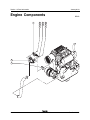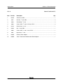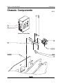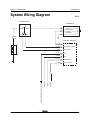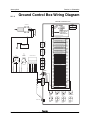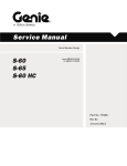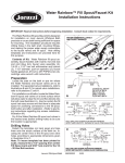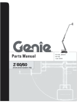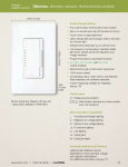
1
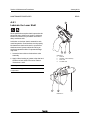
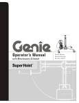
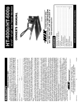
Introduction
January 2013
Important
Read, understand and obey the safety rules and
operating instructions in the Genie Z-45/25 and
Genie Z-45/25J Operator's Manual before
attempting any maintenance or repair procedure.
This Parts and Service Manual Supplement
provides service parts information and electrical
schematics for the recently released Positive Air
Shutdown System, which are not included in your
parts or service manuals. Please add this parts
information and electrical schematics to the parts
and service manuals for your machine.
This manual provides detailed parts and service
information for qualified service professionals.
Basic mechanical, hydraulic and electrical
skills are required to perform most procedures.
However, several procedures require specialized
skills, tools, lifting equipment and a suitable
workshop. In these instances, we strongly
recommend that maintenance and repair be
performed at an authorized Genie dealer
service center.
Technical Publications
Genie has endeavored to deliver the highest degree
of accuracy possible. However, continuous
improvement of our products is a Genie policy.
Therefore, product specifications
are subject to change without notice.
Readers are encouraged to notify Genie of errors
and send in suggestions for improvement. All
communications will be carefully considered for
future printings of this and all other manuals.
Contact Us:
Copyright © 2011 Terex Corporation
PO Box 97030
Redmond, WA 98073-9730 USA
128269 Rev B January 2013
First Edition, Second Printing
"Genie" and "Z" are registered trademarks of
Terex South Dakota, Inc. in the USA and many
other countries.
www.genielift.com
e-mail: [email protected]
Printed on recycled paper
Printed in U.S.A.
2
Z-45/25 • Z-45/25J
Part No. 128269
January 2013
Introduction
Table of Contents
Introduction
Important Information .......................................................................................................... 2
Section 1
Section 2
Rev
Service Parts
B
Engine Components .................................................................................................... 4
B
Chassis Components .................................................................................................. 6
Rev
Maintenance Procedures
Maintenance Inspection Report .................................................................................. 10
Section 3
B
A-3.1 Test the Automatic Engine Overspeed Control System .................................... 11
B
A-9.1 Lubricate the Lever Shaft ................................................................................. 12
Rev
Schematics
B
Introduction ................................................................................................................ 13
B
System Wiring Diagram ............................................................................................. 14
B
Ground Control Box Wiring Diagram ........................................................................... 15
Part No. 128269
Z-45/25 • Z-45/25J
3
Section 1 • Parts Information
January 2013
Engine Components
1
REV B
2
5
7
3
6
3
4
8
10
9
4
Z-45/25 • Z-45/25J
Part No. 128269
January 2013
Section 1 • Parts Information
REV B
ENGINE COMPONENTS
Item
Part No.
Description
1
101957
Solenoid, 12V DC ....................................................................................................... 1
2
6357
Hex Nut, 1/4 -20, GR 2 ................................................................................................ 2
3
6638
Flat Washer, 1/4 inch .................................................................................................. 2
4
6090
Screw - HHC, 1/4 -20 x 0.75 inch, GR 5 ...................................................................... 2
5
21130
Clevis Yoke, 1/4 -28 .................................................................................................... 1
6
21496
Nut, 1/4 -28, GR 2 ....................................................................................................... 1
7
6888
Screw - HHC, 1/4 -20 x 1 inch, GR 5 ........................................................................... 1
8
6091
Nylock Nut, 1/4 -20 ...................................................................................................... 1
9
128079
Gasket - Deutz Adapter .............................................................................................. 1
10
128065
Valve - Positive Air Shutdown with Deutz Adapter ...................................................... 1
Part No. 128269
Qty.
Z-45/25 • Z-45/25J
5
Section 1 • Parts Information
January 2013
Chassis Components
REV B
1
2
3
14
13
Ground Control Box
4
12
7
10 6 11
6
5
3
8
9
6
Z-45/25 • Z-45/25J
Part No. 128269
January 2013
Section 1 • Parts Information
REV B
CHASSIS COMPONENTS
Item
Part No.
Description
—
128064
Wire Harness - Positive Air Shutdown
1
61211
Circuit Breaker, 15A .................................................................................................... 1
2
75041
Screw - PHPM, 10-32 x 1 inch .................................................................................... 2
3
6178
Nylock Nut, 10-32 ....................................................................................................... 3
4
—
—
—
128067
128068
110984
128069
Positive Air Shutdown Controller ................................................................................. 1
Positive Air Shutdown System Software
Control Module
Control Module Label
5
6091
Nylock Nut, 1/4 -20 ...................................................................................................... 2
6
6638
Flat Washer, 1/4 inch .................................................................................................. 3
7
6884
Screw - HHC, 1/4 -20 x 2.5 inches, GR 5 .................................................................... 2
8
49826
Screw - PHPM, 10-32 x 0.625 inch, GR 2 ................................................................... 1
9
61225
Relay, 12V DC ............................................................................................................ 1
10
8915
Screw - HHC, 1/4 -20 x 1.25 inches, GR 5 .................................................................. 1
11
56912
Spring Clip, 1/4 -20 ...................................................................................................... 1
12
128031P
Control Module Mounting Bracket ............................................................................... 1
13
128200
—
—
27246
128578
Toggle Switch, SPDT 3 position, momentary (Test)
(includes mounting fasteners) ..................................................................................... 1
Toggle Switch Boot .................................................................................................... —
Screw - PHPH, 6-32 x .025 ........................................................................................ —
14
52607
Decal - Test ................................................................................................................ 1
Part No. 128269
Qty.
Z-45/25 • Z-45/25J
7
Section 1 • Parts Information
January 2013
This page intentionally left blank.
8
Z-45/25 • Z-45/25J
Part No. 128269
January 2013
REV B
Section 2 • Maintenance Procedures
Scheduled Maintenance Procedures
About This Section
This section contains detailed procedures for each
scheduled maintenance inspection.
Each procedure includes a description, safety
warnings and step-by-step instructions.
Observe and Obey:
Symbols Legend
Safety alert symbol—used to alert
personnel to potential personal
injury hazards. Obey all safety
messages that follow this symbol
to avoid possible injury or death.
Maintenance inspections shall be completed by
a person trained and qualified on the
maintenance of this machine.
Scheduled maintenance inspections shall be
completed daily, quarterly, annually and every 2
years as specified on the Maintenance
Inspection Report.
Red—used to indicate the
presence of an imminently
hazardous situation which, if not
avoided, will result in death or
serious injury.
Failure to properly complete each
inspection when required may
cause death, serious injury or
substantial machine damage.
Orange—used to indicate the
presence of a potentially
hazardous situation which, if not
avoided, could result in death or
serious injury.
Immediately tag and remove from service a
damaged or malfunctioning machine.
Repair any machine damage or malfunction
before operating machine.
Yellow with safety alert symbol—
used to indicate the presence of a
potentially hazardous situation
which, if not avoided, may cause
minor or moderate injury.
Keep records on all inspections for three years.
Unless otherwise specified, perform each
procedure with the machine in the following
configuration:
Yellow without safety alert
symbol—used to indicate the
presence of a potentially
hazardous situation which, if not
avoided, may result in property
damage.
• Machine parked on a firm, level surface
• Boom in the stowed position
• Turntable rotated with the boom between the
non-steering wheels
• Turntable secured with the turntable
rotation lock
Indicates that a specific result is expected after
performing a series of steps.
• Key switch in the off position with the key
removed
Indicates that an incorrect result has occurred
after performing a series of steps.
• Wheels chocked
• All external AC power disconnected from the
machine
Part No. 128269
Z-45/25 • Z-45/25J
9
Section 2 • Maintenance Procedures
January 2013
Maintenance Inspection Report
Model
Serial number
Date
REV B
Refer to the Genie Z-45/25 and Z-45/25J Service Manual for
scheduled machine maintenance procedures.
The following scheduled maintenance procedures will need to be
performed in addition to regularly scheduled machine maintenance
inspections as outlined in the Service Manual.
Hour meter
Machine owner
Checklist A - Rev A
Y N R
A-3.1 Lubricate lever shaft
Inspected by (print)
Inspector signature
Perform every 100 hours:
A-9.1 Lubricate lever shaft
Inspector title
Inspector company
Instructions
• Make copies of this report to use for
each inspection. Store completed
forms for three years.
• If any inspection receives an “N”, tag
and remove the machine from
service, repair and re-inspect it. After
repair, place a check in the “R” box.
Legend
Y = yes, acceptable
N = no, remove from service
R = repaired
Comments
10
Z-45/25 • Z-45/25J
Part No. 128269
January 2013
REV B
Section 2 • Maintenance Procedures
Maintenance Procedures
5 Wait approximately 5 to 10 seconds for the
solenoid valve to reset.
A-3.1
Test the Automatic Engine
Overspeed Control System
6 Start the engine from the ground controls.
Genie specifications requires that this procedure be
performed daily or every 8 hours, whichever comes
first.
Regular testing the automatic engine overspeed
control system is essential to safe machine
operation. Continued use of an improperly
lubricated lever shaft could result in a positive air
shutdown control system malfunction during an
engine overspeed condition. Component damage
may result.
Result: The engine should start and operate
normally.
Result: The engine does not start. Consult the
Genie Service Department.
Note: Perform this procedure with the machine on a
firm, level surface.
1 Pull out the red Emergency Stop Button to the
on position at both the ground and platform
controls.
2 Turn the key switch to ground control. Start the
engine from the ground controls and allow it to
idle.
3 Locate the test toggle switch on the side of the
ground control box. Move and hold the toggle
switch to the TEST position.
4 Activate high idle (rabbit symbol).
Result: The engine should shut off.
Result: The engine does not shut off. Consult
the Genie Service Department.
Part No. 128269
Z-45/25 • Z-45/25J
11
Section 2 • Maintenance Procedures
January 2013
MAINTENANCE PROCEDURES
REV B
A-9.1
Lubricate the Lever Shaft
a
Genie specifications require that this procedure be
performed every 100 hours or monthly, whichever
comes first. Perform this procedure more often if
dusty conditions exist.
Lubrication to the lever shaft is essential to safe
machine operation. Continued use of an improperly
lubricated lever shaft could result in a positive air
shutdown control system malfunction during an
engine overspeed condition. Component damage
may result.
d
1 Locate the lever shaft on the shutdown valve
assembly.
c
b
Illustration 1
a
solenoid
b
shutdown valve assembly
c
lever shaft
d
air intake tube
2 Apply a liberal coating of grease to the shaft end
surfaces on both sides of the valve. Refer to
Illustrations 1 and 2.
Grease Specification
Chevron Ultra-duty grease, EP NLGI 2 (lithium based)
or equivalent
c
b
a
Illustration 2
12
Z-45/25 • Z-45/25J
Part No. 128269
January 2013
Section 3 • Schematics
Schematics
REV B
About This Section
Electrical Schematics
Electrocution/burn hazard. Contact
with electrically charged circuits
could result in death or serious
injury. Remove all rings, watches
and other jewelry.
Observe and Obey:
Troubleshooting and repair procedures shall be
completed by a person trained and qualified on
the repair of this machine.
Immediately tag and remove from service a
damaged or malfunctioning machine.
General Repair Process
Malfunction
discovered
Repair any machine damage or malfunction
before operating the machine.
Before Troubleshooting:
Read, understand and obey the safety rules and
operating instructions in the appropriate
operator's manual on your machine.
Identify
symptoms
Troubleshoot
problem
still exists
Return to
service
problem
solved
Inspect
and test
Perform
repair
Be sure that all necessary tools and test
equipment are available and ready for use.
Part No. 128269
Z-45/25 • Z-45/25J
13
Section 3 • Schematics
January 2013
System Wiring Diagram
REV B
SOLENOID RELAY
TROMBETTA
PULL COIL
30
87
HOLD COIL
86
GROUND
85
CB1
15A
CONTROL MODULE
+
-
C1-P11
HOLD COIL
C1-P7
PULL RELAY (GND)
C1-P12
PULL RELAY
C1-P1
-12V
C1-P2
+12V
C1-10
RPM SIGNAL
C1-P9
TEST SWITCH
12V DC
TB134C
TB41B
TB 134C
CONTROL BOX GROUND SCREW
14
Z-45/25 • Z-45/25J
Part No. 128269
January 2013
Section 3 • Schematics
Ground Control Box Wiring Diagram
REV B
GROUND CONTROL BOX
TROMBETTA
4 5 6 7
Genie Industries
GND BK
HOLD RD/12
R20 BAT WH/12
1
2
3
4
5
6
7
8
9
10
TO REMOVE:
Push gently
and lift
1 3 4 7 10 9 2
1 START RELAY
2 TACHOMETER
3 START INPUT
4 AUX PWR UNIT
5 GROUND
6 BATTERY
7 TO KEY SW (DIESEL ONLY)
8 JUMP TO 7 (GAS ONLY)
9 IGN OR FUEL ON
10TEMP OR PRESS FAULT
C32
1 3 4 5 6 7 8 12
12/24 Volt IGNITON/START MODULE
+
C7B
GND BK
_
BATTERY
FUNCTIONS
C6
CB1
15A
CIRCUIT
BREAKER
CR6
SOLENOID RELAY
19/18 CABLES
C2B
C1B
TEST GR
C41 RPM OR/BK
GND BR
P134BAT RD
CR86 WH
CR85 BK
HOLD RD
P20BAT RD
P20 BAT RD
CR6 #86 WH
R20BAT WH/12
CR6 #85 BK
P20BAT1 RD/12
TS64
RUN/TEST
SWITCH
TB-134C RD
C5-1 RD
ENGINE
C5
P134 RD
C5-8 GR
TEST GR
C41 OR/BK
2 PRIMARY BOOM DOWN
2
3 PRIM BOOM FUNC CONTROL
3
4
4
5 TURNTABLE ROTATE RIGHT
5
6 TURNTABLE ROT FUNC CTRL
6
7 PRIMARY BOOM EXTEND
7
C5-7 OR/BK
GND BR
B
A
B
A
8
10
11 SECONDARY BOOM DOWN
11
12 SEC BOOM FUNC CTRL
12
14 PLATFORM LEVEL UP
14
15 PLATFORM LEVEL DOWN
15
17 PLAT ROTATE LEFT/JIB UP
17
18 PLAT ROTATE RIGHT/JIB DOWN 18
C3B
C1-P9
C1-P10
C1-P1
C1-P2
C1-P7
C1-P12
C1-P11
87
1
10 SECONDARY BOOM UP
C4B
86
TERMINAL BASE (TB)
1 PRIMARY BOOM UP
8 PRIMARY BOOM RETRACT
CONTROL MODULE
30
85
C
12V DC TO PLAT
P20 BAT RD/12
D
20 +12 VOLT POWER
20
21 IGNITION POWER
21
22 +12 VOLT TO PLATFORM
22
23 KEYSWITCH POWER
23
24 CB1 POWER
24
25 OIL PRESSURE SWITCH
25
26 OIL TEMPERATURE SWITCH
26
27 AUXILIARY PUMP
27
32 BRAKE
32
33 START ENGINE
33
34 GLOW PLUG
34
35 HIGH RPM
35
38 (SPARE)
38
39 (SPARE)
39
41 ALTERNATOR PULSE PICKUP
41
42 (SPARE)
42
44 JIB DOWN DESCENT ALARM
D
44
134 KS POWER
134
134A KS POWER
134A
C
D
N
G
CR2
POWER
RELAY
CR4
HIGH RPM
SOLENOID
RELAY
CR23
DRIVE LIGHT
OPTION RELAY
CR5
HORN
RELAY
CR32
PRIMARY
BOOM
RELAY
CR33
TURNTABLE
ROTATE
RELAY
CR37
SECONDARY
BOOM
RELAY
BR
CR1
IGNITION
START
RELAY
GROUND BOLT
Part No. 128269
Z-45/25 • Z-45/25J
15