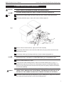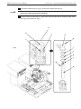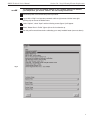
1
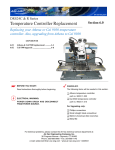
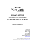
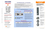
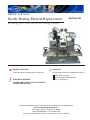
DRS24C & R Series
Nozzle Heating Element Replacement
Section 2.0
Replacing your 1000 watt nozzle heating element
☛ BEFORE YOU START:
Read instructions thoroughly before beginning.
ELECTRICAL WARNING:
CHECKLIST:
The following items will be needed in this section.
Metric Allen wrenches
1000 watt upper heating element
part no. 0024.90.116
POWER DOWN DRS24 AND DISCONNECT
FROM POWER SOURCE.
For technical problems, please contact the Air-Vac technical service department at:
Air-Vac Engineering Company, Inc.
30 Progress Avenue • Seymour, CT 06483
Phone: 203-888-9900 • Fax: 203-888-1145
e-mail: [email protected] • www.air-vac-eng.com • 03/26/01
DRS24 Technical Service Manual
Section 2.0 : Nozzle Heating Element Replacement
2.0 Nozzle Heating Element Replacement
!
IMPORTANT
NOTE
STEPS:
VERIFY DRS24 IS DISCONNECTED FROM THE POWER SOURCE.
☛
The nozzle heating element (D), (fig.2), is located in the Z-axis assembly (E).
1
Remove the two safety shield hold down screws (A), (fig.1), with a 2.5mm Allen wrench.
2
Slide safety shield (B), (fig.1), down until it rests on diffuser plate (C).
Fig. 1
C
A
NOTE
!
B
3
Remove silicone vacuum tube (F), (fig.2), from Z-axis assembly.
4
Using a 3mm Allen wrench, remove the three M4 screws (G), (fig.2) that secure the heater
head cap (H) in place.
5
Lift off heater head cap (H), being careful not to lose the heater head gasket (I).
☛
Some earlier models had a spacer ring (J), (fig.2), and an additional gasket (K). If your
machine has these, remember to re-install them when you re-assemble the unit.
6
Remove heating element (D), (fig.2).
7
Locate the new 1000w heating element, make sure the white indexing key (L), (fig.2), is
installed in the same slot as the one in the old element, insert the new element making sure
the key is to the right side of the connector and verify that it is properly seated on the bottom
of the nozzle assembly.
PROPER ORIENTATION OF THE HEATING ELEMENT IS CRITICAL. YOU CAN DOUBLE
CHECK THIS BY MAKING SURE THE EXTERNAL THERMOCOUPLE WIRE (M) ON THE
OUTSIDE OF THE ELEMENT CASING FACES TOWARD THE REAR OF THE DRS24.
WARNING
8
Re-install the heater head cap (H) and gasket (I), (fig.2), making sure to plug in the connector
in the cap to the keyed connector on top of the heating element.
2
DRS24 Technical Service Manual
9
NOTE
☛
Section 2.0 : Nozzle Heating Element Replacement
Re-install the M4 screws (G), (fig.2), to secure the heater head cap (H).
These screws should be evenly snug. If you can see the cap bending or distorting,
they are too tight and should be loosened.
10
Plug the silicone vacuum tube (F), (fig.2), back into the nozzle and re-install the safety shield
(B), (fig.1), and screws (A), (fig.1).
E
H
G
H
G
F
I
Fig. 2
J
K
L
M
D
3
DRS24 Technical Service Manual
NOTE
☛
Section 2.0 : Nozzle Heating Element Replacement
The installation of your new heating element is now complete. Before you calibrate
your temperature, you need to “Burn-in” the new heating element first.
11
Reconnect power to the DRS24 and power up module.
12
Log on with a “High” level operator password and then right mouse click the lower right
spinning chip to access the hidden menu.
13
Under “Options”, select “Open” and the following screen (figure 3) will appear.
14
Select “Heater Burn In Profile” (figure 3) then click on thumbs up.
15
Run this profile several times before calibrating your newly installed heater (see note above).
Fig. 3
4