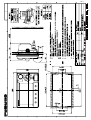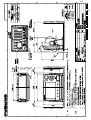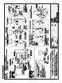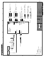
1
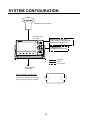
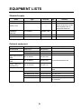
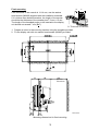
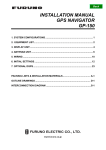
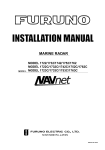
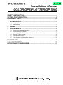
Back
Installation Manual
COLOR GPS PLOTTER GP-7000
SAFETY INSTRUCTIONS ............................................................................ i
SYSTEM CONFIGURATION ....................................................................... ii
EQUIPMENT LISTS.................................................................................... iii
1. INSTALLATION ..................................................................................... 1
1.1
1.2
Display Unit .................................................................................................................. 1
Antenna Unit................................................................................................................. 4
2. WIRING .................................................................................................. 5
3. ADJUSTMENTS .................................................................................... 9
3.1
3.2
3.3
3.4
3.5
3.6
Choosing Position Data Source.................................................................................... 9
Choosing Port I/O Format........................................................................................... 11
Calibrating NMEA Depth, Speed and Water Temperature Data ................................ 13
Waypoint, Route Format............................................................................................. 14
External Event Format ................................................................................................ 14
C-link (primary and secondary stations) ..................................................................... 15
PACKING LIST ........................................................................................ A-1
OUTLINE DRAWINGS............................................................................. D-1
INTERCONNECTION DIAGRAM ............................................................ S-1
www.furuno.co.jp
SAFETY INSTRUCTIONS
CAUTION
WARNING
ELECTRICAL SHOCK HAZARD
Observe the following compass safe
distances to prevent interference to a
magnetic compass:
Do not open the equipment
unless totally familiar with
electrical circuits and
service manual.
Only qualified personnel
should work inside the
equipment.
Display
unit
Standard
compass
Steering
compass
0.70 m
0.45 m
Use the power cable supplied with the
installation materials.
Turn off the power at the switchboard
before beginning the installation.
Use of other power cables may cause fire
or damage the equipment.
Fire or electrical shock can result if the
power is left on.
Use the proper fuse.
Use of the wrong fuse may damage the
equipment.
Organic solvent
Do not apply paint, anti-corrosive sealant
or contact spray to coating or plastic
parts of the equipment.
Those items contain organic solvents that
can damage coating and plastic parts,
especially plastic connectors.
i
SYSTEM CONFIGURATION
ANTENNA UNIT GPA-017
DISPLAY UNIT
GP-7000
NMEA1 and NMEA2 ports:
Radar, autopilot, video sounder,
temperature indicator, etc.
PC/NMEA IN port:
PC, NMEA device, buzzer
: Standard
: Option
: User Supply
Power Source
12-24 VDC
How to remove the hard cover
Place your thumbs at the center
of the cover, and then lift the cover
while pressing it with your thumbs.
ii
EQUIPMENT LISTS
Standard supply
Name
Display Unit
Type
GP-7000
Code No.
Qty
—
1
GPA-017
Antenna Unit
—
1
Installation
Materials*
CP14-06400
000-041-183
1
Accessories*
FP20-01100
000-042-239
1
Spare Parts*
SP14-03201
004-371-980
1
Remarks
System also available
without antenna (for boats
which already have an
appropriate antenna)
* See packing list at back of this manual.
Optional equipment
Name
Type
Code No.
Qty
GPS Antenna
GPA-017S
000-040-541
Antenna Cable Set
CP20-01700
004-372-110
30 m, antenna cable extension
CP20-01710
004-372-120
50 m, antenna cable extension
Right Angle Antenna
Base
No.13-QA330
000-803-239
L-angle Antenna
Base
No.13-QA310
000-803-240
Antenna Base for
Rail Mounting
No.13-RC5160
000-806-114
Mast Mounting Kit
CP20-01111
004-365-780
Cable Assy.
MJ-A6SPF0012-050C
000-154-053-10 6P – 6P, 5 m
MJ-A6SPF0012-100C
000-154-037-10 6P – 6P, 10 m
MJ-A6SPF0003-050C
000-154-054-10 6P, 5 m
MJ-A7SPF0007-050C
000-154-028-10 For connecting a PC, 5 m, with
7P connector
iii
For mounting antenna unit
For mounting antenna unit on a
mast
1. INSTALLATION
1.1 Display Unit
The display unit may be mounted on a desktop, overhead or flush mounted in a console.
Mounting considerations
Choose a mounting location for the display unit considering the following points:
• Choose a location where the controls can be easily operated.
• Leave sufficient space around the unit to facilitate checking and maintenance. See the
outline drawing at the back of this manual for recommended maintenance space.
• Locate the unit out of direct sunlight because of heat that can build up inside the cabinet.
• The operating temperature range is -15°C to 55°C (5°F to 131°F).
• Locate the unit well away from exhaust gases and other active gases.
• The location should be well ventilated.
• Choose a location where shock and vibration are minimal.
• Be sure the mounting location is strong enough to support the weight of the unit,
particularly in overhead mounting. If necessary reinforce the mounting location.
• A magnetic compass will be affected if the display unit is placed too close to the compass.
Observe the following compass safe distances to prevent deviation to the compass.
Standard compass, 0.70 m, Steering compass, 0.45 m.
1
Mounting
Desktop, overhead mounting
1. Fix the hanger to the mounting location with four self-tapping screws (5X20). See the
outline drawing on page D-1 for complete mounting dimensions.
2. Loosely screw the knob bolts into the display unit.
3. Set the display unit to the hanger and tighten the knob bolts.
4. Attach the hard cover to the display unit to protect the LCD.
FIXING
HOLE
Unit: mm
Display unit, mounting dimensions for desktop or overhead mounting
2
B
Flush mounting
A
If the thickness of the console is 11-14 mm, use the washer
head screws (M4X20) supplied with the installation materials.
If it is thicker than those dimensions, the length of the screws
should be the thickness of the console plus 7.3 mm ±1.5 mm.
The length of the threaded portion to be inserted to the display
unit should not exceed 7 mm (B≤7).
A: Thickness of console
1. Prepare a cutout in the mounting location using the template provided.
2. Fix the display unit with six washer head screws (M4X20) provided.
52
80
150
Service
Clearance
Unit: mm
Mounting dimensions for flush mounting
3
1.2 Antenna Unit
Refer to the antenna unit outline drawing at the back of this manual for mounting
instructions.
When selecting a mounting location consider the following points:
• Select a location out of the radar and Inmarsat beams. Those beams will obstruct or
prevent reception of the GPS satellite signal.
• There should be no interfering object within the line-of-sight to the satellites. Objects
within line-of-sight to a satellite, for example, a mast, may block reception or prolong
acquisition time.
• Locate the antenna well away from the antenna of a VHF radiotelephone to prevent
interference.
• Mount the antenna unit as high as possible. Mounting it this way keeps it free of
interfering objects and water spray, which can interrupt reception of GPS satellite signal if
the water freezes.
Note: If the antenna cable is to be passed through a hole in a bulkhead which is too small
to pass the connector, disassemble the connector with radio pincers and a monkey
wrench. After passing the cable through the hole assemble the connector as below.
Gasket
Washer
Shield
Clamping Nut
Pin (Solder.)
Housing
How to assemble the antenna connector
4
2.
WIRING
The figure below shows the basic wiring scheme.
ANTENNA UNIT
GPA-017
FROM LEFT
PC/NMEA IN: PC, NMEA device, buzzer, AIS
NMEA 2:
Radar, autopilot, video sounder,
temperature indicator, etc.
NMEA 1:
Same as NMEA 2
Ground
Antenna Cable, 10 m
MJ-A15A3F0013-035-3A,
3.5 m
Black
White
Shield
Power
Source
Display unit, rear view
Power source
The power source is a 12-24 VDC battery. Be sure the power cable is tightly fastened to the power
source and the polarity (plus and minus) is correct. Connect the white lead to the positive terminal
(+) and the black lead to the negative terminal (-).
5
Ground
Connect the ground wire to the boat's grounding bus. If the unit is not grounded, noise may result.
If noise is a problem on an FRP vessel, fasten a ground plate of 20 cm x 30 cm to the outside of
the ship's hull and connect the ground wire there.
Use a closed-type lug (
(
).
) for the connection on the display unit. Do not use an open-type lug
Antenna cable
Types of antenna cables
If a longer length of antenna cable is required, use the optional antenna cable set, which is available in 30 and 50 m lengths.
Antenna cable set
Antenna cable
set
Code no.
Contents
CP20-01700
004-372-110
1) Converter cable assy. NJ-T-3DX-1, Code No. 000-123
2) Vinyl tape NO.360 Code No. 000-835-215
3) Connector N-P-8DFB-CF, Code No. 000-156-918-10
4) Self-bonding tape U-tape, Code No. 000-165-833-10
5) Antenna cable assy. 8D-FB-CV*30m*, Code No. 000-117-547
CP20-01710
004-372-120
Items 1) - 4) above plus:
Antenna cable assy. 8D-FB-CV*50m*, Code No. 000-117-549
Connecting the antenna cable
Antenna Unit
GPA-017
Connector fitted at factory.
Antenna Cable
Connect at
rear of
display unit
10 m
Connection of antenna unit GPA-017
Antenna Unit
GPA-017S
20 cm
Connector fitted at factory
ANTENNA CABLE KIT
Conversion Cable
Assy.
1m
Antenna Cable
30 m or 50 m
1m
Connect at
rear of
display unit
Attached during installation
(See page 8.)
Connection of antenna cable set on antenna unit GPA-017S (option)
6
Waterproofing the connector
If you are using the extension cable, connect the cable and then wrap the connector with
self-vulcanizing tape and then vinyl tape to waterproof it. Bind ends of vinyl tape with cable
ties (local supply) to prevent unraveling.
How to waterproof the connector
7
How to attach N-P-8DFB connector (for extension cable kit)
Outer Sheath
Armor
Dimensions in millimeters.
Inner Sheath Shield
50
Remove outer sheath and armor by the dimensions
shown left.
Expose inner sheath and shield by the dimensions
shown left.
30
Cover with heat-shrink tubing and heat.
Cut off insulator and core by 10 mm.
10
30
Twist shield end.
Flat Washer
Slip on clamping nut, flat washer, gasket and clamp
as shown left.
Clamping
Nut
Gasket Clamp
(reddish
brown)
Aluminum Foil
Fold back shield over clamp and trim.
Trim shield here.
Cut aluminum foil at four places, 90° from one
another.
Insulator
Washer 2
Fold back aluminum foil onto shield and trim.
Trim aluminum
tape foil here.
Remove insulator up to edge of washer 2.
5
Clamping Nut
Pin
Expose the core by 5 mm.
Spacer
Housing
Solder through
the hole.
Slip the pin onto the conductor. Solder them together
through the hole on the pin.
Insert the spacer and housing. Screw the clamping
nut into the housing.
(Tighten by turning the clamping nut. Do not tighten
by turning the housing.)
How to attach N-P-8DFB connector
8
3.
ADJUSTMENTS
This chapter shows you how to adjust your unit, from the menu. When choosing item or option
from the menu, you may use the [ENTER] knob or the CursorPad ( ). For sake of brevity the
descriptions contained herein use the [ENTER] knob.
3.1
Choosing Position Data Source
If you intend to use a position data from a source other than the internal GPS receiver follow the
procedure below. Otherwise, go to paragraph 3.2.
1. Press the [MENU] key to show the menu bar.
Menu Bar
GENERAL
PLOTTER
MAP
ALARMS
ADVANCED
INFO
FIND
Menu bar
2. Rotate the [ENTER] knob to choose ADVANCED from the menu bar and then push the
[ENTER] knob.
FIX
NAVIGATE
COMPASS
INPUT/OUTPUT
EXT NMEA
GPS SIMULATION
ECHO SOUNDER SIMULATION On
AIS SETUP
C-MAP WEATHER SERVICE
SYSTEM UPDATE
ADVANCED menu
9
3. Rotate the [ENTER] knob to choose INPUT/OUTPUT and then push the [ENTER] knob.
INTERNAL GPS SETUP
NMEA 1 INPUT
NMEA 1 OUTPUT
NMEA 2 INPUT
NMEA 2 OUTPUT
RS232/NMEA 3 INPUT
RS232C 3 OUTPUT
INPUT 3 MODE
WPL/RTE FORMAT
EXTERNAL EVENT
C-LINK
NMEA-0183 4800-N81-N
NMEA-0183 4800-N81-N
NMEA-0183 4800-N81-N
RS232C
Standard
Off
Off
INPUT/OUTPUT menu
4. Rotate the [ENTER] knob to choose INTERNAL GPS SETUP and then push the
[ENTER] knob.
RESTART GPS
INTERNAL GPS
On
DIFF CORR SOURCE WAAS
WAAS SEARCH
Auto
INTERNAL GPS SETUP menu
5. Rotate the [ENTER] knob to choose INTERNAL GPS and then push the [ENTER] knob.
Off
On
6. Rotate the [ENTER] knob to choose Off or On and then push the [ENTER] knob.
Off: Use external navigator
On: Use internal GPS navigator
7. Press the [MENU] key to close all open windows and erase the menu bar.
10
3.2
Choosing Port I/O Format
1. Press the [MENU] key to show the menu bar.
2. Rotate the [ENTER] knob to choose ADVANCED from the menu bar and then push the
[ENTER] knob.
3. Rotate the [ENTER] knob to choose INPUT/OUTPUT and then push the [ENTER] knob.
4. Rotate the [ENTER] knob to choose appropriate INPUT or OUTPUT item and then push the
[ENTER] knob.
GLL
VTG
BWR
DBT
DPT
MTW
VHW
WCV
APA
APB
HDG
BOD
XTE
RMA
RMB
RMC
GGA
HSC
AAM
GTD
MWV
ZDA
WPL
RTE
TLL OUT
NMEA-0183 1200-N81-N
NMEA-0183 4800-N81-N
NMEA-0183 4800-N82-N
NMEA-0183 9600-N81-N
NMEA-0183 9600-O81-N
C-COM
AIS 38400
Disabled
NMEA 1/NMEA 2/
RS232/NMEA 3 Input*
On
On
Off
Off
Off
Off
Off
Off
Off
On
Off
Off
Off
Off
On
On
Off
Off
Off
Off
Off
Off
On
On
On
RS232CW
NMEA
(Choose format for
PC/NMEA IN port)
INPUT 3 MODE*
*: For AIS, set as below.
RS232/NMEA3 INPUT: "AIS 38400"
INPUT 3 MODE: "RS232C"
NMEA1/NMEA2/RS232 Output
NMEA 1 INPUT, NMEA 1 OUTPUT menus
5. Do one of the following depending on item selected.
Input
1) Rotate the [ENTER] knob to choose appropriate option and then push the [ENTER] knob.
Below is the meaning of the NMEA options. "C-COM" is for connection of a GSM modem.
For details about the GSM modem, see its owner's manual.
NMEA-0183 4800-N81-N
1
2
3 4 5 6
1
2
3
4
5
6
Data format
Baud rate: 1200, 4800, 9600(bps)
Parity: N (No parity) or O (Odd parity)
Character length (8)
Stop bit: 1 or 2
X-On/Off (non)
Description of NMEA options
2) Press W to close the window.
11
Output
1) Rotate the [ENTER] knob to choose appropriate option and then push the [ENTER] knob.
Off
On
2) Rotate the [ENTER] knob to choose Off or On as appropriate and then push the [ENTER]
knob followed by W.
6. Repeat step 5 to set up other ports.
7. Press the [MENU] key to close all open windows and erase the menu bar.
I/O format
Port
Input
Output
I/O format
Data sentence
Remarks
NMEA 1, NMEA 2
IEC-61162-1,
NMEA-0183
Ver. 1.5/2.0/3.0
See table below.
PC/NMEA IN
RS232, and IEC
and NMEA above
For NMEA IN, see
table below.
NMEA 1, NMEA 2
IEC-61162-1,
NMEA-0183
Ver. 1.5/2.0/3.0
GLL, VTG, BWR, DBT, BWR: Rhumb line
DPT, MTW, VHW,
WCV, APA, APB, HDG,
BOD, XTE, RMA,
RMB, RMC, GGA,
HSC, WPL, RTE, TLL,
AAM, GTD, MWV, ZDA
PC/NMEA IN
RS232
Input data, sentence priority
Data
Sentence priority order
Speed thru water
VHW
True heading
HDT, HDG, HDM
Magnetic heading
HDT, HDG, HDM
Target position
TLL
Radiotelephone target position
DSC, DSE
Waypoint data
RMB
Depth
DPT, DBT
Water temperature
MTW
Wind current, speed
MWV
12
Remarks
3.3 Calibrating NMEA Depth, Speed and Water
Temperature Data
NMEA speed, depth and water temperature data may be corrected from the GP-7000 if they
cannot be done from the equipment that outputs the data. Enter a minus value if the actual
value is lower than the NMEA data, or a plus value if the actual value is higher than the
NMEA data. For example, if the actual water temperature is 20° and the water temperature
data output by the sensor is 17°, enter +3(°).
1. Press the [MENU] key to show the menu bar.
2. Rotate the [ENTER] knob to choose ADVANCED from the menu bar and then push the
[ENTER] knob.
3. Rotate the [ENTER] knob to choose EXT NMEA and then push the [ENTER] knob.
DRAFT SETUP
+00.0 Ft
SPEED CALIBRATION +00 %
TEMP CALIBRATION +00.00 F
EXT NMEA menu
4. Rotate the [ENTER] knob to choose appropriate item.
DRAFT SETUP: Enter ship’s draft to get NMEA depth from sea surface (instead of
transducer).
SPEED CALIBRATION: Enter offset in percentage points to correct NMEA speed
indication.
TEMP CALIBRATION: Enter offset to correct NMEA water temperature indication.
5. Push the [ENTER] knob. The cursor is selecting the plus sign (or minus sign). If it is
necessary to switch from plus to minus or vice versa, rotate the [ENTER] knob to
choose plus or minus and then push the [ENTER] knob. If not necessary, go to step 6.
6. Push the [ENTER] knob, rotate the [ENTER] knob to set digit and then push the
[ENTER] knob. To clear a line of data, press the [CLR FLD] soft key, which is the third
key from the left of the keys below the screen.
Setting range
Draft setup: -20 - +39.9(ft)
Speed calibration: -50 - +50(%)
Temp calibration: -50 - +50(°F)
7. Set other digits as you did in step 6.
8. Press the [SAVE] soft key, which is the fourth key from the left of the keys below the
screen.
9. If necessary, repeat step 4-8 to choose and set another calibration item.
10. Press the [MENU] key to close all open windows and erase the menu bar.
13
3.4
Waypoint, Route Format
You may transfer waypoint and route data to another GP-7000 series unit or a PC in Standard or
Furuno format, via the NMEA1 port, NMEA2 port or PC NMEA IN port.
1. Press the [MENU] key to show the menu bar.
2. Rotate the [ENTER] knob to choose ADVANCED from the menu bar and then push the
[ENTER] knob.
3. Rotate the [ENTER] knob to choose INPUT/OUTPUT and then push the [ENTER] knob.
4. Rotate the [ENTER] knob to choose WPL/RTE FORMAT and then push the [ENTER] knob.
Standard
Furuno
5. Choose Furuno or Standard as appropriate and then push the [ENTER] knob.
Standard: NMEA format WPL and RTE sentences are output when "SEND" is executed to
transfer waypoint list or route list.
Furuno: Furuno format WPL and RTE sentences are output when "SEND" is executed to
transfer waypoint list or route list. Waypoint color, shape and comment data are sent.
6. Press the [MENU] key to close the menu.
3.5
External Event Format
If the equipment is equipped with an external event switch you may choose what mark is inscribed
on the screen when the switch is pressed. For connection of an external event switch, see the interconnection diagram.
1. Press the [MENU] key to show the menu bar.
2. Rotate the [ENTER] knob to choose ADVANCED from the menu bar and then push the
[ENTER] knob.
3. Rotate the [ENTER] knob to choose INPUT/OUTPUT and then push the [ENTER] knob.
4. Rotate the [ENTER] knob to choose EXTERNAL EVENT and then push the [ENTER] knob.
Off
WPT
MOB
5. Choose Off, WPT or MOB as appropriate and then push the [ENTER] knob.
Off: No event switch is connected.
WPT: Waypoint is registered at ship's position if the cursor is not displayed, or at cursor position if the cursor is displayed.
MOB: MOB is registered at ship's position.
6. Press the [MENU] key to close the menu.
14
3.6 C-link (primary and secondary stations)
The C-link feature, available when several GP-7000 series units are interconnected via
NMEA ports or PC/NMEA IN ports (see the illustration below), lets you duplicate on
secondary stations the destination set at the primary station. With this feature active
destination may only be set from the primary station.
Primary station
GP-7000
series
NMEA1
NMEA2
PC/NMEA IN
Secondary station
NMEA1
GP-7000
series
NMEA2
PC/NMEA IN
Secondary station
NMEA1
GP-7000
series
NMEA2
*
*
*: Either port
**: Either port
PC/NMEA IN
Secondary station
NMEA1
GP-7000
series
NMEA2
**
**
Note: Secondary stations cannot
be connected to one another.
PC/NMEA IN
1. Press the [MENU] key to show the menu bar.
2. Rotate the [ENTER] knob to choose ADVANCED from the menu bar and then push the
[ENTER] knob.
3. Rotate the [ENTER] knob to choose INPUT/OUTPUT and then push the [ENTER] knob.
4. Rotate the [ENTER] knob to choose C-LINK and then push the [ENTER] knob.
Secondary Station
Primary Station
Off
5. Choose Secondary Station, Primary Station or Off as appropriate and then push the
[ENTER] knob.
Secondary Station: This unit is designated as the secondary station. Destination
cannot be set or changed from the secondary station.
Primary Station: This unit is designated as the primary station.
Off: C-link feature is turned off.
Note: When three or more units are installed, designate only one unit as the primary
station. All other units should be designated as secondary stations. If you
designate two units as primary units, the message “Both chart plotters are set as
Primary station” appears and the buzzer sounds.
6. Press the [MENU] key to close the menu.
15
NAME
**
1
1
Q'TY
000-162-608-10
000-802-081-00
5X20 SUS304
5X20 SUS304
000-162-652-10
000-804-742-00
M4X20 SUS304
M4X20 SUS304
100-323-890-00
14-074-1032-0
100-332-651-10
02-155-1082-1
000-155-850-10
000-549-063-00
(略図の寸法は、参考値です。 DIMENSIONS IN DRAWING FOR REFERENCE ONLY.)
4
6
1
CP14-06400
1
FP20-01100
SP14-03201
FGB0-A 125V 3A PBF
1
FGBO-A 3A AC125V
000-041-184-00
GP-7000-E-C
000-041-403-00
GPA-017
DESCRIPTION/CODE №
DOCUMENT
OUTLINE
1/1
000-149-985-1*
E42-00401-*
000-149-134-1*
OM*-44290-*
000-149-135-1*
OS*-44290-*
000-149-136-1*
IM*-44290-*
000-145-880-00
**
**
**
MJ-A15A3F0013-035-3A
000-154-054-10
MJ-A6SPF0003-050C
DESCRIPTION/CODE №
14CR-X-9851 -12
1
1
1
1
1
1
Q'TY
TWO TYPES AND CODES MAY BE LISTED FOR AN ITEM. THE LOWER PRODUCT MAY BE SHIPPED IN PLACE OF
THE UPPER PRODUCT. QUALITY IS THE SAME.
14CR-X-9851
型式/コード番号が2段の場合、下段より上段に代わる過渡期品であり、どちらかが入っています。 なお、品質は変わりません。
TEMPLATE
フラッシュマウント型紙
OPERATOR'S MANUAL
取扱説明書
OPERATOR'S GUIDE
操作要領書(英)
INSTALLATION MANUAL
装備要領書
図書
POWER CABLE
ケーブル組品MJ
SIGNAL CABLE ASSEMBLY
ケーブル組品MJ
NAME
GP-7000/F-E-C-017,GP-7000/F-E-N-017
1.コ-ド番号末尾の[**]は、選択品の代表型式/コードを表します。
CODE NUMBER ENDED BY "**" INDICATES THE NUMBER OF TYPICAL MATERIAL.
SELF-TAPPING SCREW
+トラスタッピンネジ 1シュ
WASHER HEAD SCREW
+ナベセムスネジB
OUTLINE
INSTALLATION MATERIALS
ACCESSORIES
SPARE PARTS
UNIT
FLUSH MOUNTING SPONGE
Fマウントヨウスポンジ
工事材料
FILTER CLEANER
フイルタークリーナー
付属品
FUSE
ヒューズ
予備品
DISPLAY UNIT
指示器
ANTENNA UNIT
空中線部
ユニット
PACKING LIST
A-1
NAME
**
1
Q'TY
000-154-054-10
(略図の寸法は、参考値です。 DIMENSIONS IN DRAWING FOR REFERENCE ONLY.)
1
4
6
1
CP14-06400
1
FP20-01100
MJ-A6SPF0003-050C
000-162-608-10
000-802-081-00
5X20 SUS304
5X20 SUS304
000-162-652-10
000-804-742-00
M4X20 SUS304
M4X20 SUS304
100-323-890-00
14-074-1032-0
100-332-651-10
02-155-1082-1
000-155-850-10
000-549-063-00
SP14-03201
FGB0-A 125V 3A PBF
1
FGBO-A 3A AC125V
000-041-184-00
GP-7000-E-C
DESCRIPTION/CODE №
NAME
DOCUMENT
OUTLINE
1/1
000-149-985-1*
E42-00401-*
000-149-134-1*
OM*-44290-*
000-149-135-1*
OS*-44290-*
000-149-136-1*
IM*-44290-*
000-145-880-00
**
**
**
MJ-A15A3F0013-035-3A
DESCRIPTION/CODE №
14CR-X-9852 -13
1
1
1
1
1
Q'TY
TWO TYPES AND CODES MAY BE LISTED FOR AN ITEM. THE LOWER PRODUCT MAY BE SHIPPED IN PLACE OF
THE UPPER PRODUCT. QUALITY IS THE SAME.
14CR-X-9852
型式/コード番号が2段の場合、下段より上段に代わる過渡期品であり、どちらかが入っています。 なお、品質は変わりません。
TEMPLATE
フラッシュマウント型紙
OPERATOR'S MANUAL
取扱説明書
OPERATOR'S GUIDE
操作要領書(英)
INSTALLATION MANUAL
装備要領書
図書
POWER CABLE
ケーブル組品MJ
GP-7000/F-E-C,GP-7000/F-E-N
1.コ-ド番号末尾の[**]は、選択品の代表型式/コードを表します。
CODE NUMBER ENDED BY "**" INDICATES THE NUMBER OF TYPICAL MATERIAL.
SIGNAL CABLE ASSEMBLY
ケーブル組品MJ
SELF-TAPPING SCREW
+トラスタッピンネジ 1シュ
WASHER HEAD SCREW
+ナベセムスネジB
OUTLINE
INSTALLATION MATERIALS
ACCESSORIES
SPARE PARTS
UNIT
FLUSH MOUNTING SPONGE
Fマウントヨウスポンジ
工事材料
FILTER CLEANER
フイルタークリーナー
付属品
FUSE
ヒューズ
予備品
DISPLAY UNIT
指示器
ユニット
PACKING LIST
A-2
Y. Hatai
D-1
Y. Hatai
D-2
Y. Hatai
hatai
2005.12.19
11:57:12
+09'00'
D-3
D-4
Mar,27'07 R.Esumi
C
B
A
GPA-017S
NJTP-3DXV-1
1m,φ5.3
注記
*1)造船所手配。
*2)オプション。
*3)コネクタは現地にて取付け。
NOTE
*1. SHIPYARD SUPPLY
*2. OPTION
*3. ATTACH CONNECTOR LOCALLY.
TNC-P-3
*2
N-J-3
12-24 VDC
ANTENNA UNIT
GPA-017
TNC-J-3
空中線部
ANTENNA UNIT
10m,φ5.5
空中線部
0.2m
*3
N-P-8DFB
N-J-3
8D-FB-CV
30/50m,φ14.3
MJ-A15A3F0013
3.5m,φ8.0
2
3A
NJTP-3DXV-1
1m,φ5.3
1
TNC-P-3
TNC-P-3
MJ-A3SPF
シロ WHT
クロ BLK
1
2
3
(+)
(-)
SHIELD
12-24 VDC
DWG No.
SCALE
APPROVED
TD2-A
TD2-B
RD2-H
RD2-C
NC
SHIELD
NMEA2
NMEA1
TD1-A
TD1-B
RD1-H
RD1-C
NC
SHIELD
C4429-C01- F
MASS
Y. Hatai
kg
E. MIYOSHI
1
2
3
4
5
6
7
1
2
3
4
5
6
1
2
3
4
5
6
REF No.
4
6
7
SHIELD
5
6
12V_P
BUZZER
BUZZER
3
4
7
RD3-H
RD3-C
SHIELD
NAME
名称
TITLE
P
INTERCONNECTION DIAGRAM
COLOR GPS PLOTTER
相互結線図
カラーGPSプロッタ
GP-7000
ブザー
BUZZER
(0.1A)
アカ RED
クロ BLK
イベントスイッチ
EVENT SW
NMEA0183
Ver1.5/2.0/3.0
パソコンなど
PC ETC.
NMEA0183 Ver1.5/2.0/3.0
IEC 61162-1
NMEA0183 Ver1.5/2.0/3.0
IEC 61162-1
キ YEL
ミドリ GRN
*2
MJ-A7SPF0007-050C,5m,φ6
シロ WHT
アオ BLU
キ YEL
ミドリ GRN
*2
MJ-A6SPF0003-050C,5m,φ6
MJ-A6SPF0012-050C/100C,5/10m
シロ WHT
クロ BLK
キ YEL
ミドリ GRN
MJ-A6SPF0003-050C,5m,φ6
シロ WHT
クロ BLK
キ YEL
ミドリ GRN
14-074-5000
P
P
MJ-A7SPF
P
P
MJ-A6SPF
P
P
MJ-A6SPF
GND
*1
IV-1.25sq.
RS232C_TD
RS232C_RD
RD3-H
RD3-C
12V_P
BUZZER
SHIELD
PC/NMEA IN
TAKAHASHI.T
DRAWN
MAY 8, '06
CHECKED
GPS-SIG
GPS-SHIELD
ANT
指示部
DISPLAY UNIT
GP-7000
3
S-1
N-P-8DFB
The paper used in this manual
is elemental chlorine free.
・FURUNO Authorized Distributor/Dealer
9-52 Ashihara-cho,
Nishinomiya, 662-8580, JAPAN
Telephone : +81-(0)798-65-2111
Fax
: +81-(0)798-65-4200
All rights reserved.
Printed in Japan
A : AUG . 2004
C1 : JUN . 21, 2007
Pub. No. IME-44290-C1
(HIMA )
GP-7000
*00014913612*
*00014913612*
* 0 0 0 1 4 9 1 3 6 1 2 *