1
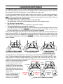
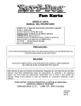
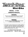
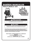
MODEL: 30033, 30034 OWNERS MANUAL WARNING: Read Tecumseh Engine Owners Manual and Important Rules for Safe Operation before Operating Vehicle WARNING: YOU MUST ADD OIL TO THE ENGINE PRIOR TO USE!!! 1 ¼ PINTS OF SAE 30 MOTOR OIL This vehicle is sold for off-road use only. Before operating this vehicle, read all the instructions for safe assembly and operation as well as the instructions governing the engine and other portions of the vehicle. Pay close attention to all caution and warning labels on the Fun-Kart. For Replacements Parts Call: 1-888-389-5522 (U.S.) 1-888-707-1880 (Canada) 05/02/02 01639 Rev. D Read These Important Rules For Safe Operation NOTE: All the items (1-33) below should be read and understood by the Operator and Parent. Failure to follow these instructions could endanger personal safety of the operator and any passenger. 1. This vehicle is not licensable. IT IS NOT TO BE OPERATED ON ANY PUBLIC ROAD, STREET, SIDEWALK or ALLEY. To do so would be a violation of local law. This vehicle may be operated only on private property and upon areas approved by local law. 2. This vehicle should NEVER be operated indoors. The exhaust from the engine contains carbon monoxide, which is tasteless, odorless, and poisonous gas. 3. This Fun-Kart is not intended nor designed for racing. 4. The operator of this vehicle should always wear a D.O.T approved helmet and other protective equipment as recommended by state and local laws. The operator should also wear face shields or goggles, boots, gloves, and other appropriate protective clothing. 5. Unless otherwise specified in this manual, all screws, nuts, and bolts must be kept tight to ensure that the vehicle is in safe operating condition. The engine must be kept free of all dirt and other accumulations, paying particular attention to throttle linkage area. 6. Prevailing Torque type locknuts lose their locking capability with repeated use and require replacement. Ensure locknuts are functioning properly. 2 7. The tire pressure should be checked prior to each use. The recommended inflation pressure is the maximum tire pressure which is printed on the tires sidewall. Improper tire pressure may cause instability and may prevent proper braking or steering. 8. Modification of this vehicle or removal of any original equipment or safety decals may render the vehicle unsafe or illegal. Never remove any chained guard, or belt clutch guard. These covers are for the riders protection. 9. The vehicle should never be started without first checking to see that the throttle is in idle position. Do not start engine without verifying proper function of the throttle. 10. Never attempt to start this vehicle without having the operator sitting in the proper position to ensure control of the kart. 11. The operators ability to operate this off-road vehicle safely is largely dependent upon the operators ability to exercise proper judgement. An operator also must not be too small or too large for controlled operation. The operator must be at least 16 years of age and have understanding, mental capacity and physical capability to safely operate this vehicle. This vehicle should only be operated after mature, supervised instruction and sufficient practice in non-congested areas. 12. This vehicle is designed for one operator and one passenger. A passenger on any vehicle must be sufficient age, understanding, mental capacity, and physical capability to act to protect himself/ herself, and wear a D.O.T approved helmet at all times. This kart is not recommended for cumulative weights exceeding 250 pounds. 13. The engine should be stopped when the vehicle is not in use. 14. Loose clothing, long hair, or articles worn by any riders must be fully contained, or covered to prevent them from possibly being caught in rotating parts of the vehicle or the surrounding environment while riding. Failure to obey could endanger the personal safety of the Riders. 15. Do not place hands, feet, or any other part of the body or any clothing near the engine, muffler, wheels, chain, and other rotating parts of the vehicle while riding or running the engine. Caution must be used in performing required maintenance on or near an operating engine. Special caution should be taken after the engine has been running, since the engine and other drive components may be extremely hot. 16. Wet, slippery, rough, or steep terrain is potentially dangerous and may result in injury if proper caution is not observed. Slow speeds are required to safely operate this vehicle under those conditions. The Operator must use mature judgement, skill, and experience to choose a speed suitable for the terrain and riding conditions. 17. The Governor settings for this vehicles engine must not be tampered with, altered or changed. The governor is set by the engine manufacturer and limits the maximum speed of the engine (and vehicle) and protects the engine from damage. Excessive speeds are potentially dangerous to the rider and the engine. 3 18. Each time before using this vehicle, the fuel supply should be checked. The fuel tank should never be filled while the engine is running or while the engine is hot. Do not fill tank in closed area such as a garage, while smoking, or in the vicinity of an open flame. Do not overfill the tank. Always allow at least ¼ inch of space at the top of the tank for expansion. Never top off tank. Replace cap tightly to prevent spillage of fuel and potential fire hazard. After filling tank, move the vehicle at least 15 feet away from spot of filling before starting. 19. If the vehicle should start making unusual noise or vibrating abnormally, the engine should be stopped and the spark plug wire disconnected. The vehicle should then be checked for damage. Excessive noise or vibration is generally a warning of loose or worn parts. 20. When making repairs or adjustments to the vehicle which do not involve adjustments to the engine, the spark plug wire must be disconnected and kept away from the spark plug to prevent accidental starting. When working on or around or when restarting engine, use extreme caution to avoid contact with the muffler, cylinder head, or any other potentially hot area on or around the engine. 21. Always perform a Pre-Ride Inspection before starting the engine. See Pre-Ride Inspection in the manual. 22. The custom brush guard assembled on this vehicle is for deflecting loose vegetation and must not be removed. 23. When storing the vehicle, it must be kept in a place where gasoline fumes will not reach an open flame or spark. For long periods of storage, such as for winter, the fuel tank should be drained in the open, cool area. The engine must be allowed to cool before storage in any enclosure. Read and keep all printed material supplied with this vehicle. Timely and specific instructions and an Operators Manual revisions are included in supplements. If any printed material included is unclear, please call 1-888-389-5522 for assistance. 24. Never operate this vehicle while under the influence of alcohol, drugs, or medication of any kind. Such operation could be dangerous to you and/or others. 25. Always slow down while turning. High speed turning may cause loss of control, possible injury to the Operator. 26. Do not race, jump, and perform stunt riding or spinouts when operating the Fun-Kart. The Fun-Kart is not designed or intended for such operation. 27. This manual provides guidelines for the assembly, maintenance, and operation of this Fun-Kart and is not intended as a service manual. 28. Assembly, maintenance, and/or repair of this Fun-Kart should only be performed by persons of sufficient mechanical skill, experience, and judgment (such as outdoor equipment dealers, motorcycle dealer/shops, or small engine dealers) so that no unsafe condition or modification is made. 29. Always use extreme caution when starting the engine. Avoid touching the engine, muffler, or drive components. These areas could cause burns on contact. 30. Operator must always be appropriately supervised at all times while operating this vehicle. 4 31. Riding your Fun-Kart requires skill acquired through practice over a period of time. Take the time to learn the basic techniques before attempting to ride the vehicle. 32. Ride only on safe and familiar terrain. Avoid loose gravel and rocks. Be careful on wet surfaces and allow for extra braking distance. 33. ALWAYS mount the caution flag provided on the Fun-Kart for safety purposes. This flag could help prevent dangerous situations. Pay close attention to all Caution and Warning labels on the Fun-Kart. ASSUMPTIONS OF RISK The Owner Or Operator Assumes All The Risks Incident To Or Arising Out Of The Operation Of This Vehicle. Failure To Follow And Comply With All Warnings May Cause Serious Injury Or Death 5 YERF-DOG Fun-Karts by Flexible Flyer LIMITED WARRANTY The Limited Warranty on this vehicle is in two (2) parts: We offer the original purchaser of this product the following warranty: PART 1 ENGINE Tecumseh warrants the engine for (2) years, not Flexible Flyer. See Tecumseh Engine Owners Manual. Engine repair, replacement parts, and warranty claims must be handled through an authorized dealer in your locality. Tecumseh has an extensive authorized sales and service dealer network. (See yellow pages of phone directory under Engine-Gas). PART 2 FRAME The frame and related components are warranted by Flexible Flyer and are applied to any part found to be defective due to material and/or workmanship when inspected at the Flexible Flyer factory. Flexible Flyer will at its option, repair or replace the defective parts to the original purchaser at no charge. The warranty periods are as follows from the date of purchase: A. Frame for 90 days, Void if: 1. Frame is broken or bent due to abuse (underside scraped abusively). 2. Wheels are bent or broken due to impact. 3. Spindles are bent due to impact. 4. Paint is worn off of rear bumper indicating an extra rider. 5. Axles are bent out of ordinary position either horizontally or vertically. 6. Non-Factory altering of engine or its components B. Bearings and sprocket for 30 days C. Clutch for 30 days against breakage of its parts. No warranty is applied for wear of clutch shoes or clutch bearings due to service. D. Throttle cable, brake cable, brake band, chain, tires, seat, shocks, fasteners and other components are not warranted because due to normal service they are subject to excessive wear and abuse. All Warranties are voided if the vehicle has been altered in any way or is used in racing or competition, rented, used under abnormal conditions, or subject to abuse, misuse, neglect, or improper maintenance. Flexible Flyer is not liable for any damage claim or liability claim, personal or otherwise resulting from the operation of this vehicle in any way. 6 FLEXIBLE FLYER 100 Tubb Avenue West Point, MS 39773 FOR REPLACEMENT PARTS PLEASE CALL: 1-888-389-5522 (U.S.) 1-888-707-1880 (Canada) ASSEMBLY 1. Complete the Fun-Kart registration and warranty confirmation on the back of this owners manual and mail in within 10 days of purchase. The information is required when ordering parts. 2. Steering Wheel - Bolt the steering wheel to the anchor plate with fasteners provided in the parts bag included with the Fun-Kart. See Steering Wheel Assembly Instructions page 12. 3. Seat - Install the seat frame to chassis frame with fasteners provided in the parts bag. See Seat Assembly Instructions page 13. 4. Brush Guard - Bolt the brush guard to chassis frame with fasteners provided in the parts bag. See Brush Guard Instructions page 14. 5. Foam - Attach Foam to Brush Guard. See Foam Attachment Diagram page 15. 6. Bolts - Check the screws, nuts and bolts on your vehicle to see that all are tightened securely. For safe operating conditions, do periodic checks and tighten securely. 7. Engine - Fill the crankcase with oil until it reaches the threads in the filler plug neck. (Approximately 1¼ pints) with SAE 30 weight oil. For additional information refer to Tecumseh engine manual for servicing the engine. 8. Fill fuel tank with regular gasoline, leaded or unleaded. Do not use premium gasoline. Do not overfill (No fuel in filler neck). 9. Tire Pressure CHECK AIR PRESSURE IN TIRES!! It is common industry practice to overinflate the tires. This is done to guarantee an airtight seal. Prior to riding the Fun-Kart for the first time, you may need to reduce the air pressure in the tires to the specifications stated below: Rear Tires Front Tires 10 PSI 12 PSI Proper tire pressures will increase the life of the tire and enhance the performance of the Fun-Kart. Driving on asphalt or concrete will significantly reduce the life of the tire!! 7 PRE-RIDE INSPECTION WARNING - Perform this pre-ride inspection everyday before riding the vehicle. If not performed, serious damage to the vehicle and personal injury may result. 1. Engine Oil Level Add oil if required. Check for leaks. Tighten filler cap securely. 2. Fuel Level Add fuel if necessary. Do not overfill (no fuel in filler neck). Replace cap tightly. Check for leaks. Do not mix oil with gas. Only refuel when engine is off and cool. 3. Brakes Perform a Brake Test: Sit in the vehicle with the brake actuated by pressing on the brake pedal. Start the engine with the ignition switch on. Increase the engine RPM gradually to ensure the brake is effective. Do not operate this Fun-Kart unless the brake is working properly. 4. Tires Check conditions and pressure. 5. Drive Chain Check condition, tension, lubricate as necessary. 6. Throttle Check for smooth operation. Assure throttle snaps back to idle. Also, check for frayed cable or damaged cable conduit. If either condition exists replace the cable assembly before riding. 7. Stop Switch Perform this stop switch test. While the engine is running, move the steering column remote stop switch to the OFF position. If this does not stop the engine, move the engine remote switch to the OFF position. If the engine is not equipped with an engine remote switch, pull the spark plug wire. Check to insure that the stop switch wire is attached to the terminal on the engine. Do not operate this vehicle with a stop switch that is not functioning properly. 8. All Nuts, Bolts and Fasteners Check wheels to assure that all axle nuts and lug nuts are tightened properly. Check and tighten all other fasteners as necessary. Regularly check set screws on sprockets and drum. 9. Guards Ensure all protective guards are in place. Never remove any chain guard, or clutch guard. Each of these covers have a protective purpose, if removed it could endanger the personal safety of the operator or passenger. 10. Steering System Ensure that it turns freely. STARTING INSTRUCTIONS NOTE: Do not attempt to start or operate this machine without being completely familiar with all controls necessary to operate this vehicle safely. Do not start the engine before reading and understanding all the rules, warnings, and instructions in this manual. 8 1. Before starting the engine, the operator should be seated in the Fun-Kart. If the rider is not seated in the vehicle, it should be placed against a stationary object and started. 2. Do not start the engine before checking to make sure the throttle assembly is in the idle position. Warning Each time prior to starting the engine, check throttle assembly to ensure that when the throttle pedal (right side) is pushed all the way forward the assembly is working smoothly and returns to idle when released. Do not operate if pedal and engine throttle linkage fail to return to idle. 3. To start a cold engine, pump the engine primer 3 times. If the engine is hot, priming may not be necessary to restart the engine. 4. Pull recoil starter rope sharply. See Tecumseh engine owners manual. Do not flood the engine by continuously pulling the starter rope. If engine does not start after two or three pulls of the starter rope, wait a few minutes then repeat the above procedures. OPERATIONAL SAFETY TIPS TURNING MANUEVERS The new rider must learn to shift his weight and control the throttle to allow the rear tires to negotiate the turn. This is the primary technique to be mastered in riding this vehicle. Practice turning at slow constant speeds. Defer increased speeds until you are confident of your proficiency and are intimately familiar with the terrain. Steer in the direction of the turn, and lean your body to the inside of the turn in order to maximize front tire traction. Use the throttle to maintain posture throughout the turn. Incorrect turning techniques may cause the front tires to slide straight ahead without affecting the vehicles direction of travel. If this should occur, come to a stop, then resume the technique outlined above. If the front wheels tend to skid in mud, sand, or snow, you may be able to improve control by releasing the throttle and allowing the vehicle to coast through the turn. If rear wheel inadvertently skid sideways, correct your slide by steering in the direction of the skid, if you have room to perform this maneuver safely. Avoid braking or accelerating until you have control. To avoid skids while traveling on slippery terrain, the rider must exercise a high degree of caution. Turning maneuvers on slippery terrain are more hazardous than those performed under full traction and must be done slowly. PREVENTIVE MAINTENANCE STORAGE In the event your vehicle is not to be operated for a period in excess of 30 days and at the end of riding season prepare for storage as follows: WARNING - Do not drain fuel while engine is hot. Be sure to move vehicle outside before draining fuel. 9 1. Drain fuel tank and remove all fuel remaining in the tank by using a suction device or by soaking up the fuel with a clean rag or towel. Remove all fuel remaining in the carburetor by allowing engine to run out of fuel. Do not perform any fuel removal procedure while smoking or near an open flame. Dispose of any rags or towels properly. 2. Lubricate engine cylinder by removing the spark plug and pouring an ounce of lean lubricating oil through the spark plug hole into the cylinder. Crank the engine slowly to spread oil and replace spark plug. 3. Do not save or store gasoline over winter. Using old gasoline that has deteriorated from storage will cause hard starting and affect engine performance. 4. When the vehicle is removed from storage re-read the owners manual, perform any assembly required, and perform a pre-ride inspection. See Pre-Ride Inspection section of this manual. GENERAL Just as your automobile needs professional, mechanical maintenance from time to time, so does this vehicle. Replacement of the spark plug and ignition points is made necessary by normal use. Professional air-cooled engine service is easily obtained. Check your phone book yellow pages under Engine Gasoline. SERVICE INSTRUCTIONS Engine Lubrication You must change the oil in the crankcase after the first two hours of operating your new engine and after each 25 hours of use thereafter. That will insure proper lubrication in internal parts and prevent costly repairs due to excessive wear. Refer to Engine Maintenance Instructions. Kart Lubrication Every two or three hours of use lubricate the following items with several drops of oil; steering bearing points, brake rod pivot points, pedal pivot points, steering spindles, and steering rod ends. Use the same grade of lubricating oil that is used in the engine crankcase. Chain Lubrication For the best chain life, it should be lubricated with a graphite type of lubricant such s the spray-on type which evaporates leaving the graphite on the chain. Using oil or grease on the chain in dusty or sandy riding conditions may cause dirt particles to stick to the chain resulting in rapid wear from abrasion. Front Wheel Replacement Care must be used when replacing wheels. Do not over tighten nuts. It is only necessary to tighten the nuts so that the wheel turns freely on the axle with minimum endplay. If the wheel does not turn freely the nut is too tight. Rear Wheel Replacement Loosen the large locknut in the center of the wheel to remove the rear wheel. Chain Adjustment After the first two hours of operation, check the chain adjustment and readjust it if it has more than 1/2 flex. Loosen the engine clamp nuts and slide the engine forward to tighten chain. For Replacement Parts Please Call: 1-888-389-5522 (U.S.) 1-888-707-1880 (Canada) 10 SUSPENSION MAINTENANCE The Suspension System on your Fun-Kart is specifically designed and set up for the smoothest possible ride, while maintaining top performance and kart durability. Your Fun-Karts suspension system uses two shock absorbers on the front suspension , to comfortably tackle rough terrain. The two front shock absorbers affect the camber or slant of your front tires. You may have noticed that your new Fun-Kart has an extreme outward camber or slant of the front tires as shown in Figure A. This is normal. They were set this way at the factory for ensuring maximum tread life on the front tires. There are three important reasons for this outward camber: 1. The weight of the driver and/or passenger is not on the Kart. The added weight of the driver and/or passenger pushes the front suspension down. 2. The Fun-Kart is not in motion. When the Kart is in motion, the front suspension is forced down slightly. 3. The shock absorbers are new and not broken in. Your new Fun-Kart needs at least one hour of use to break in the shocks and level out the tires. After the first 30 minutes of use, the outward camber may be reduced by one half. After 1 hour of use the tires may have almost no or slight outward camber as shown in Figure B. When your Fun-Kart gets an inward camber on the front tires from shock wear as shown in Figure C and steering becomes difficult, the shocks will need to be readjusted. Adjust the front suspension to a slight outward camber as shown in Figure B by increasing the shocks. Adjust the shocks by following the Shock Absorber Adjustment instructions below. When your shocks cannot be adjusted any tighter, they must be replaced. A. EXTREME OUTWARD CAMBER (NEW SHOCKS, NOT BROKEN IN) B. SLIGHT OUTWARD CAMBER (SHOCKS BROKEN IN) C. INWARD CAMBER (SHOCKS NEED TO BE ADJUSTED OR REPLACED) Your Fun Kart has an added feature on the A-Arms for three quick Camber Adjustments Figure D. Note: The factory attaches the shocks at position 2. You may choose to move them to position 1 and adjust shocks to set at Slight Outward Camber (Riding Position) until the shocks break in then either readjust the shocks as shown in Shock Absorber Adjustment or move to position 2. Shocks may bottom out (cannot be adjusted any tighter) DISPLAY POSITION RIDING POSITION before you need to set to position 3. To adjust: Remove 3/8 x 1-3/4 Bolts and 3/8 Nylock Nuts attaching the bottom of the Shocks to the Three Hole Brackets and move to desired hole then reattach Shocks. Tighten Bolts. NOTE: Outside holes can be used for new kart display purposes with new shocks. (Setting at NO CAMBER) SLIGHT OUTWARD CAMBER NO CAMBER POSITION 1 (OUTSIDE HOLE) POSITION 2 (MIDDLE HOLE) 11 POSITION 3 (INSIDE HOLE) D. THREE QUICK CAMBER ADJUSTMENTS SHOCK ABSORBER ADJUSTMENT SHOCK ADJUSTMENT HOLE 1. Locate the SHOCK ABSORBERS (77) at the front of the FUN-KART 2. The SHOCKS are pre-set for normal conditions at the factory. 3. Locate the SHOCK ADJUSTMENT HOLE at the base of the spring. 4. Place the end of a narrow screwdriver in the SHOCK ADJUSTMENT HOLE. 77 SHOCK ABSORBER 5. Turn the SHOCK ADJUSTMENT HOLE counter-clockwise around the SHOCK to decrease shock absorption. 6. Turn the SHOCK ADJUSTMENT HOLE clockwise around the SHOCK to increase shock absorption. 7. Experiment with the adjustment until the desired effect is attained. STEERING WHEEL ASSEMBLY INSTRUCTIONS 90 STEERING WHEEL 1/4 NYLOCK NUT 9 1/4 - 20 x 1-3/4 HEX HEAD BOLT 57 STEERING WHEEL STEERING SHAFT 89 STEERING SHAFT 90 89 STEERING WHEEL CAP 9 STEERING WHEEL HARDWARE Item 9 57 A Description Qty. BOLT, 1/4"-20 X 1-3/4" HEX 3 NUT, 1/4" - 20 NYLOCK 3 SCREW 1 1/4 - 20 x 1-3/4 HEX HEAD BOLT 12 PHILLIPS HEAD SCREW SEAT ASSEMBLY INSTRUCTIONS 6 1. Locate the SEAT FRAME (75), LAP BELTS, and SHOULDER BELTS (74). 2. Align STUDS on the bottom of the SEAT FRAME (75) with the SEAT TAB HOLES on the FUN-KART FRAME. Attach the LAP BELT (74) connectors to the TAB on the back of the SEAT FRAME (75) using the hardware shown. 7. Place the SEAT CUSHION (42) on the SEAT FRAME (75). Secure the bottom of the SEAT CUSHION to the SEAT FRAME using using the hardware shown. 3. Slip SHOULDER BELT (74) connectors onto the rear STUDS on the bottom of the SEAT FRAME (75). 8. Insert the LAP BELTS (74) through the center of the SEAT CUSHION (42). 4. Insert STUDS into SEAT BRACKET HOLES on FRAME. SHOULDER BELTS 5. Secure the SEAT FRAME using the hardware shown. LAP BELTS SEAT CUSHION Item 9 11 61 59 100 102 99 110 SEAT HARDWARE Description Bolt 1/4-20 x 1-3/4 HEX Bolt, 3/8-16 x 1-1/2 HEX Nut, 5/16 LOCK Nut, 3/8-16 NYLOCK Washer, 3/8 Flat Washer, 5/16 Flat Washer, 1/4 Flat Washer, 1/4 Lock Qty 1 1 4 1 2 4 1 1 SEAT FRAME STUDS FUN-KART FRAME SEAT BRACKET 13 BRUSH GUARD ASSEMBLY INSTRUCTIONS 1. Secure the MAIN BRUSH GUARD (30) to the middle tabs on the FUN-KART FRAME, beside the SEAT, using the hardware shown. 5. Join and secure the FRONT BRUSH GUARD (29) to the ends of the REAR BRUSH GUARDS (31) using the hardware shown. 2. Secure the REAR BRUSH GUARD (31) and SAFETY FLAG (47) to the rear tabs on the FRAME using the hardware shown. 6. Mount the connectors of the SHOULDER BELT to the inside of the MAIN BRUSH GUARD (30) using the hardware shown. NOTE: Do not overtighten the hardware attaching the end of the SHOULDER BELT. The BELT must rotate. 3. Align holes and secure the REAR BRUSH GUARDS (31) to the top of the MAIN BRUSH GUARD (30) using the hardware shown. 7. For added security, strap the SAFETY FLAG (47) tightly to the the REAR BRUSH GUARD (31) using WHITE CABLE TIE (33). Cut off and discard the excess CABLE TIE. 4. Secure the FRONT BRUSH GUARD (29) to the front tabs on the FRAME using the hardware shown. REAR BRUSH GUARD SAFETY FLAG FRONT BRUSH GUARD MAIN BRUSH GUARD WHITE WIRE TIE SHOULDER BELTS TAB TAB TAB FUN-KART FRAME TAB BRUSH GUARD HARDWARE TAB TAB 14 Item 18 19 21 22 61 83 102 104 Description BOLT, 5/16-18 x 1 HEX BOLT, 5/16-18 x 1-1/2 HEX BOLT, 5/16-18 x 1-3/4 HEX BOLT, 5/16-18 x 2-1/4 HEX NUT, 5/16-18, NYLOCK SPACER, PLASTIC, BLACK WASHER, 5/16 FLAT WASHER, 5/16 LOCK Qty 5 1 2 4 10 1 22 2 FOAM ATTACHMENT DIAGRAM Attach FOAM (48) to the BRUSH GUARDS using CABLE TIES (32) as shown. 15 SUGGESTED DECAL APPLICATION Apply Decal kit (62000600) as shown in the illustrations below. (Note: Decals are self-adhesive and require no glue.) Yerf Dog logo (2) and Paw Prints (8). Yerf Dog logo (2) applied to both sides of front. Yerf Dog logo (2) applied to both sides of rear. 16 MODEL 30033 (BLUE) REPLACEMENT PARTS IDENTIFICATION Item Part No. Description Item Part No. Description 1 2 3 4 5 6 7 8 9 10 11 12 13 14 15 16 17 18 19 20 21 22 23 24 25 26 27 28 29 30 31 32 33 34 35 36 37 38 39 40 41 42 43 44 45 46 47 48 49 50 51 52 53 54 55 01758 01757 01132 H93110W H99502W H92010W Q43203W 22001400 H32503W H33137W 00922 H61610W 22000300 00920 22000900 01225 H95188W H93290W 2200040 2200030 H33135W 00996 H33136W H36254W 22001700 H92130W H92140W 01638 01627 01629 01630 M12501W M13501W M01001W 36000700 00994 01626 00204 H92690W 03238 H91480W 42000000 62000600 02908 02907 Q43160W H92700W M72038W H91820W H91830W 01204 01067 H92250W H91931W H91780W 56 57 58 59 60 61 62 63 64 65 66 67 68 69 70 71 72 73 74 75 76 77 78 79 80 81 82 83 84 85 86 87 88 89 90 91 92 93 94 95 96 97 98 99 100 101 102 103 104 105 106 107 108 109 110 01639 001203P 00995 001205P HH37524 HH1256T 01226 HH62518 HH10014 F23100W 27000100 32011606 02976 H91470W 01528 H32505W H93200W H93210W 26000900 01617 H92740W 02972B 00951 00919 00983 01133 00513 001467P 01764 01765 H55030W H92541W 23001100 01637 H92561W Q33100W 35000600 02063 02064 46000030 46000040 Q43200W Q43201W 001812P 001616P H53441W 001618P H53132W 000891P H56251W 00925 01964 001474P 03152 000710P A-ARM, LEFT, BLUE A-ARM, RIGHT, BLUE AXLE SHAFT BEARING RETAINER BEARING, 5/8" I.D. BEARING, 1" I.D. BELT, DRIVE BOLT, 1/4-20 X 1-1/2" HEX BOLT, 1/4-20 X 1-3/4" HEX BOLT, 3/8-16 X 1" CARRIAGE BOLT, 3/8-16 X 1-1/2" HEX BOLT, 3/8-16 X 1" HEX BOLT, 3/8-16 X 1-3/4" HEX BOLT, 3/8-16 X 2" CARRIAGE BOLT, 3/8-16 X 2" HEX BOLT, 5/16-18 X 5/8" HEX BOLT, 5/16-18 X 3/4" CARRIAGE BOLT, 5/16-18 X 1-1/2" CARRIAGE BOLT, 5/16-18 X 1" HEX BOLT, 5/16-18 X 1-1/2" HEX BOLT, 5/16-18 X 1-3/4" HEX BOLT, 5/16-18 X 2-1/4" HEX BOLT, 5/16-24 X 1/2" HEX BOLT, 5/8-18 X 3-3/4" HEX BOLT, 5/8-18 X 7" HEX BRAKE BAND BRAKE DRUM, 4" DIA. BRAKE ROD BRUSH GUARD, FRONT, BLUE BRUSH GUARD, MAIN, BLUE BRUSH GUARD, REAR, BLUE CABLE TIE, 11" CABLE TIE, 23" CABLE TIE, 3-1/4" CABLE, 40" THROTTLE CHAIN, DRIVE CHASSIS FRAME, BLUE CLIP, SPRING CLIP, WIRE CLUTCH MOUNT PLATE, BLUE COLLAR, 7/16 BORE X 7/8 O.D. CUSHION, SEAT DECAL SET, GRAY DRIVE COVER, PLASTIC DRIVE COVER MOUNTING BRACKET ENGINE, 6.0 H.P. TECUMSEH FLAG, SAFETY FOAM, BLACK TUBE FOOT PEDAL, LEFT FOOT PEDAL, RIGHT JACKSHAFT, 5/8" DIAMETER KEY, 1/4" X 1/4" X 1" KEY, 1/4" X 1/4" X 2" KEY, 3/16" X 3/16" X .86 MANUAL, ENGINE 17 MANUAL, OWNERS, 30033, 30034 NUT, 1/4-20 NYLOCK NUT, 3/8-16 JAM NUT, 3/8-16 NYLOCK NUT, 3/8-24, THIN NYLOCK NUT, 5/16-18 NYLOCK NUT, 5/16-18, JAM NUT, 5/8-18 THIN NYLOCK NUT;HEX;1-14;THIN;NYLOCK PAD, NON-SKID PIN, SPRING PITMAN ARM, BLUE RETAINER, BRAKE BAND, ZINC RING, 1/4" RETAINING RING, 1" RETAINING SCREW, 1/4-20 X 1/2" SELF-TAP HEX SCREW, 1/4-24 X 1/4" SET SCREW, 5/16-18 X 0.312 SET SEAT BELT, RETRACTABLE SEAT FRAME SEAT RAIL PAIR SHOCK ABSORBER, BLACK SLEEVE, 13-1/8" PVC SLEEVE, 2-3/8" PVC SLEEVE, 4-5/8" PVC SPACER, DRIVE SPACER, SPINDLE SPACER, BLACK PLASTIC SPINDLE, LEFT, BLUE SPINDLE, RIGHT, BLUE SPRING, COMPRESSION SPROCKET, 10 TOOTH SPROCKET, 60 TOOTH STEERING SHAFT STEERING WHEEL, 13" SWITCH, KILL THROTTLE ROD TIE ROD, LEFT TIE ROD, RIGHT TIRE, TURF TREAD, FRONT TIRE, TURF TREAD, REAR TORQUE CONVERTER, DRIVEN TORQUE CONVERTER, DRIVER WASHER, 1/4" FLAT WASHER, 3/8" SPECIAL FLAT WASHER, 5/16" FENDER WASHER, 5/16" FLAT WASHER, 5/16" INTERNAL TOOTH WASHER, 5/16" LOCK WASHER, 5/8" NARROW FLAT WIRE, 107" KILL SWITCH TUBE, BEARING SPACER SCREW; SHEET METAL #10 x 1/2 CAP; VINYL; SCREW WASHER, 1/4 LOCK MODEL 30034 (RED) REPLACEMENT PARTS IDENTIFICATION Item Part No. Description Item Part No. Description 1 2 3 4 5 6 7 8 9 10 11 12 13 14 15 16 17 18 19 20 21 22 23 24 25 26 27 28 29 30 31 32 33 34 35 36 37 38 39 40 41 42 43 44 45 46 47 48 49 50 51 52 53 54 55 01756 01755 01132 H93110W H99502W H92010W Q43203W 22001400 H32503W H33137W 00922 H61610W 22000300 00920 22000900 01225 H95188W H93290W 2200040 2200030 H33135W 00996 H33136W H36254W 22001700 H92130W H92140W 01638 01633 01635 01636 M12501W M13501W M01001W 36000700 00994 01626 00204 H92690W 03257 H91480W 42000000 00918 02908 02907 Q43160W H92700W M72038W H91820W H91830W 01214 01067 H92250W H91931W H91780W 56 57 58 59 60 61 62 63 64 65 66 67 68 69 70 71 72 73 74 75 76 77 78 79 80 81 82 83 84 85 86 87 88 89 90 91 92 93 94 95 96 97 98 99 100 101 102 103 104 105 106 107 108 109 110 01639 001203P 00995 001205P HH37524 HH1256T 01226 HH62518 HH10014 F23100W 27000100 00322 02976 H91470W 01528 H32505W H93200W H93210W 26000900 01617 H92740W 02972B 00951 00919 00983 01133 00513 001467P 01766 01767 H55030W H92541W 23001100 01637 H92561W Q33100W 35000600 02063 02064 46000030 46000040 Q43200W Q43201W 001812P 001616P H53441W 001618P H53132W 000891P H56251W 00925 01964 001474P 03152 000710P A-ARM, LEFT, RED A-ARM, RIGHT, RED AXLE SHAFT BEARING RETAINER BEARING, 5/8" I.D. BEARING, 1" I.D. BELT, DRIVE BOLT, 1/4-20 X 1-1/2" HEX BOLT, 1/4-20 X 1-3/4" HEX BOLT, 3/8-16 X 1" CARRIAGE BOLT, 3/8-16 X 1-1/2" HEX BOLT, 3/8-16 X 1" HEX BOLT, 3/8-16 X 1-3/4" HEX BOLT, 3/8-16 X 2" CARRIAGE BOLT, 3/8-16 X 2" HEX BOLT, 5/16-18 X 5/8" HEX BOLT, 5/16-18 X 3/4" CARRIAGE BOLT, 5/16-18 X 1-1/2" CARRIAGE BOLT, 5/16-18 X 1" HEX BOLT, 5/16-18 X 1-1/2" HEX BOLT, 5/16-18 X 1-3/4" HEX BOLT, 5/16-18 X 2-1/4" HEX BOLT, 5/16-24 X 1/2" HEX BOLT, 5/8-18 X 3-3/4" HEX BOLT, 5/8-18 X 7" HEX BRAKE BAND BRAKE DRUM, 4" DIA. BRAKE ROD BRUSH GUARD, FRONT, RED BRUSH GUARD, MAIN, RED BRUSH GUARD, REAR, RED CABLE TIE, 11 CABLE TIE, 23" CABLE TIE, 3-1/4" CABLE, 40" THROTTLE CHAIN, DRIVE CHASSIS FRAME, BLUE CLIP, SPRING CLIP, WIRE CLUTCH MOUNT PLATE, RED COLLAR, 7/16 BORE X 7/8 O.D. CUSHION, SEAT DECAL SET, RED / YELLOW DRIVE COVER, PLASTIC DRIVE COVER MOUNTING BRACKET ENGINE, 6.0 H.P. TECUMSEH FLAG, SAFETY FOAM, BLACK TUBE FOOT PEDAL, LEFT, FOOT PEDAL, RIGHT, RED JACKSHAFT, 5/8" DIAMETER KEY, 1/4" X 1/4" X 1" KEY, 1/4" X 1/4" X 2" KEY, 3/16" X 3/16" X .86" MANUAL, ENGINE 18 MANUAL, OWNERS, 30033, 30034 NUT, 1/4-20 NYLOCK NUT, 3/8-16 JAM NUT, 3/8-16 NYLOCK NUT, 3/8-24, THIN NYLOCK NUT, 5/16-18 NYLOCK NUT, 5/16-18, JAM NUT, 5/8-18 THIN NYLOCK NUT;HEX;1-14;THIN;NYLOCK PAD, NON-SKID PIN, SPRING PITMAN ARM, RED RETAINER, BRAKE BAND RING, 1/4" RETAINING RING, 1" RETAINING SCREW, 1/4-20 X 1/2" SELF-TAP HEX SCREW, 1/4-24 X 1/4" SET SCREW, 5/16-18 X 0.312 SET SEAT BELT, RETRACTABLE SEAT FRAME SEAT RAIL PAIR SHOCK ABSORBER SLEEVE, 13-1/8" PVC SLEEVE, 2-3/8" PVC SLEEVE, 4-5/8" PVC SPACER, DRIVE SPACER, SPINDLE SPACER, BLACK PLASTIC SPINDLE, LEFT, RED SPINDLE, RIGHT, RED SPRING, COMPRESSION SPROCKET, 10 TOOTH SPROCKET, 60 TOOTH STEERING SHAFT STEERING WHEEL, 13" SWITCH, KILL THROTTLE ROD TIE ROD, LEFT TIE ROD, RIGHT TIRE, TURF TREAD, FRONT TIRE, TURF TREAD, REAR TORQUE CONVERTER, DRIVEN TORQUE CONVERTER, DRIVER WASHER, 1/4" FLAT WASHER, 3/8" SPECIAL FLAT WASHER, 5/16" FENDER WASHER, 5/16" FLAT WASHER, 5/16" INTERNAL TOOTH WASHER, 5/16" LOCK WASHER, 5/8" NARROW FLAT WIRE, 107" KILL SWITCH TUBE, BEARING SPACER SCREW; SHEET METAL #10 x 1/2 CAP; VINYL; SCREW WASHER, 1/4 LOCK 45 108 44 109 103 23 109 107 19 MODEL 3003 SERIES VEHICLE REGISTRATION AND WARRANTY CONFIRMATION IMPORTANT! Please return this information within 10 days of purchase to validate your warranty. Return to: F.F. Acquisition Corp. YERF-DOG Warranty Dept. P.O. Box 1296 West Point, MS 39773 Thank-you for purchasing this fine YERF-DOG product. With proper use, maintenance and service this kart will bring many years of fun and enjoyment. Please complete this vehicle registration and warranty confirmation form to ensure protection under the terms and conditions of the warranty and to verify ownership of this product. To ensure maximum safety while operating your YERF-DOG Fun Kart, observe the following precautions: OPERATE THIS KART OFF ROAD ONLY ADULT SUPERVISION FOR OPERATORS UNDER 16 YEARS OLD WEAR A D.O.T. APPROVED HELMET, PROTECTIVE EYE WEAR, AND CLOTHING SECURE LONG HAIR AND LOOSE CLOTHING; KEEP ARMS, LEGS, AND FEET INSIDE THE KART DO NOT OPERATE UNDER THE INFLUENCE OF DRUGS OR ALCOHOL To ensure maximum owner satisfaction and understanding of this product, you should: READ OWNERS MANUAL BEFORE OPERATING KART REVIEW AND FULLY UNDERSTAND THE KART AND ENGINE WARRANTIES INSPECT THE KART UPON DELIVERY SECURE A COMPLETED COPY OF THIS CERTIFICATE FOR YOUR RECORDS In signing this document, the purchaser acknowledges that he/she understands the warranty limitations, safety, and maintenance guidelines outlined above and in the owners manual and, therefore, agrees that all riders/operators will adhere to these specifications. Model No. Serial No. First Name Initial Date of Purchase Last Name Street Address City State Zip Code Home Telephone Number Parents Signature (Please enclose a copy of your proof of purchase.) 20