1
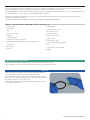
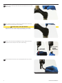
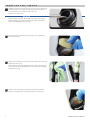
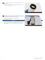
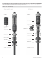
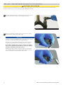
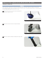
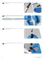
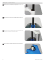
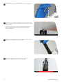
Sektor, Recon,
30 Gold, 30 Silver
Service Manual
GEN.0000000004923 Rev B
© 2015 SRAM, LLC
SRAM LLC WARRANTY
EXTENT OF LIMITED WARRANTY
Except as otherwise set forth herein, SRAM warrants its products to be free from defects in materials or workmanship for a period of two years after
original purchase. This warranty only applies to the original owner and is not transferable. Claims under this warranty must be made through the retailer
where the bicycle or the SRAM component was purchased. Original proof of purchase is required. Except as described herein, SRAM makes no
other warranties, guaranties, or representations of any type (express or implied), and all warranties (including any implied warranties of
reasonable care, merchantibility, or fitness for a particular purpose) are hereby disclaimed.
LOCAL LAW
This warranty statement gives the customer specific legal rights. The customer may also have other rights which vary from state to state (USA), from
province to province (Canada), and from country to country elsewhere in the world.
To the extent that this warranty statement is inconsistent with the local law, this warranty shall be deemed modified to be consistent with such law, under
such local law, certain disclaimers and limitations of this warranty statement may apply to the customer. For example, some states in the United States
of America, as well as some governments outside of the United States (including provinces in Canada) may:
a.Preclude the disclaimers and limitations of this warranty statement from limiting the statutory rights of the consumer
(e.g. United Kingdom).
b.Otherwise restrict the ability of a manufacturer to enforce such disclaimers or limitations.
For Australian customers:
This SRAM limited warranty is provided in Australia by SRAM LLC, 1333 North Kingsbury, 4th floor, Chicago, Illinois, 60642, USA. To make a warranty
claim please contact the retailer from whom you purchased this SRAM product. Alternatively, you may make a claim by contacting SRAM Australia, 6
Marco Court, Rowville 3178, Australia. For valid claims SRAM will, at its option, either repair or replace your SRAM product. Any expenses incurred in
making the warranty claim are your responsibility. The benefits given by this warranty are additional to other rights and remedies that you may have
under laws relating to our products. Our goods come with guarantees that cannot be excluded under the Australian Consumer Law. You are entitled to
a replacement or refund for a major failure and for compensation for any other reasonably foreseeable loss or damage. You are also entitled to have the
goods repaired or replaced if the goods fail to be of acceptable quality and the failure does not amount to a major failure.
LIMITATIONS OF LIABILITY
To the extent allowed by local law, except for the obligations specifically set forth in this warranty statement, in no event shall SRAM or its third party
suppliers be liable for direct, indirect, special, incidental, or consequential damages.
LIMITATIONS OF WARRANTY
This warranty does not apply to products that have been incorrectly installed and/or adjusted according to the respective SRAM user manual. The SRAM
user manuals can be found online at sram.com, rockshox.com, avidbike.com, truvativ.com, or zipp.com.
This warranty does not apply to damage to the product caused by a crash, impact, abuse of the product, non-compliance with manufacturers
specifications of usage or any other circumstances in which the product has been subjected to forces or loads beyond its design.
This warranty does not apply when the product has been modified, including, but not limited to any attempt to open or repair any electronic and
electronic related components, including the motor, controller, battery packs, wiring harnesses, switches, and chargers.
This warranty does not apply when the serial number or production code has been deliberately altered, defaced or removed.
This warranty does not apply to normal wear and tear. Wear and tear parts are subject to damage as a result of normal use, failure to service according
to SRAM recommendations and/or riding or installation in conditions or applications other than recommended.
Wear and tear parts are identified as:
•Dust seals
•Bushings
•Air sealing o-rings
•Glide rings
•Rubber moving parts
•Foam rings
•Rear shock mounting hardware
and main seals
•Upper tubes (stanchions)
•Stripped threads/bolts (aluminium,
titanium, magnesium or steel)
•Brake sleeves
•Brake pads
•Chains
•Sprockets
•Cassettes
•Shifter and brake cables (inner
and outer)
•Handlebar grips
•Shifter grips
•Jockey wheels
•Disc brake rotors
•Wheel braking surfaces
•Bottomout pads
•Bearings
•Bearing races
•Pawls
•Transmission gears
•Spokes
•Free hubs
•Aero bar pads
•Corrosion
•Tools
•Motors
•Batteries
Notwithstanding anything else set forth herein, the battery pack and charger warranty does not include damage from power surges, use of improper
charger, improper maintenance, or such other misuse.
This warranty shall not cover damages caused by the use of parts of different manufacturers.
This warranty shall not cover damages caused by the use of parts that are not compatible, suitable and/or authorised by SRAM for use with SRAM
components.
This warranty shall not cover damages resulting from commercial (rental) use.
TABLE OF CONTENTS
RockShox Suspension Service......................................................................................................................................................... 4
Parts and Tools Needed for Service.............................................................................................................................................................................................. 4
Lower Leg Removal............................................................................................................................................................................ 5
Solo Air Spring Service (Sektor gold, Recon Gold, 30 Gold).................................................................................................... 7
Solo Air Anatomy....................................................................................................................................................................................................................................7
Solo Air Spring Removal/Service Instructions.......................................................................................................................................................................... 8
Optional - All Travel Configuration................................................................................................................................................................................................. 11
Solo Air Spring Installation................................................................................................................................................................................................................ 11
Solo Air spring service (Recon Silver, Sektor Silver, 30 Silver)............................................................................................... 14
Solo Air Anatomy..................................................................................................................................................................................................................................14
Solo Air Spring Removal....................................................................................................................................................................................................................14
Optional - All Travel Configuration................................................................................................................................................................................................ 17
Solo Air Spring Installation............................................................................................................................................................................................................... 17
Damper Service (Sektor Gold, Recon Gold, 30 Gold)...............................................................................................................20
Damper Removal..................................................................................................................................................................................................................................20
Damper Installation............................................................................................................................................................................................................................. 23
Damper Service (Sektor Silver, Recon Silver, 30 Silver)........................................................................................................... 25
Damper Removal.................................................................................................................................................................................................................................. 25
Damper Installation............................................................................................................................................................................................................................. 28
Coil Spring Service (30 Silver, Recon Silver, Sektor Silver, Recon Gold, Sektor Gold).......................................................31
Coil SpringRemoval............................................................................................................................................................................................................................. 31
Coil Spring Installation Instructions............................................................................................................................................................................................. 33
Lower Leg Installation.....................................................................................................................................................................34
SAFETY FIRST!
We care about YOU. Please, always wear your safety glasses and
protective gloves when servicing RockShox products.
Protect yourself! Wear your safety gear!
RockShox Suspension Service
We recommend that you have your RockShox suspension serviced by a qualified bicycle mechanic. Servicing RockShox suspension
requires knowledge of suspension components as well as the special tools and fluids used for service.
For exploded diagram and part number information, please refer to the Spare Parts Catalog available on our web site at www.sram.com.
For order information, please contact your local SRAM distributor or dealer.
Information contained in this publication is subject to change at any time without prior notice. For the latest technical information,
please visit our website at sram.com.
Your product‘s appearance may differ from the pictures/diagrams contained in this publication.
P a r t s a n d To o l s N e e d e d F o r S e r v i c e
• Safety glasses
• Rubber mallet
• Nitrile gloves
• Schrader valve core tool
• Apron
• 2.5 mm hex wrench
• Clean, lint-free rags
• 5 mm hex wrench
• Fluid pan
• 24 mm socket wrench
• Isopropyl alcohol
• Torque wrench
• RockShox 15wt suspension fluid
• 5 mm hex bit socket
• Liquid O-Ring® PM600 military grease or SRAM® butter
• Large internal retaining ring pliers
• Shock pump
• Pick
• Bike stand
• Long plastic or wooden dowel
• Syringe
• Magnet
SAFETY INSTRUCTIONS
Always wear safety glasses and nitrile gloves when working with suspension fluid.
Place a fluid pan on the floor underneath the area where you will be working on the fork.
NOTIC E
Inspect each part for scratches. Do not scratch any sealing surfaces
when servicing your suspension. Scratches can cause leaks.
When replacing seals and o-rings, use your fingers or a pick to remove
the seal or o-ring. Spray isopropyl alcohol on each part and clean with a
rag. Apply grease to the new seal or o-ring.
Only use SRAM® Butter or LIquid O-Ring PM600 military grease when
servicing RockShox Forks.
4
RockShox Suspension Service
Lower Leg Removal
1
Remove the air valve cap from the top cap located on the non-drive
side fork leg.
2
Use a small hex wrench to depress the Schrader valve and release
all of the air pressure from the air chamber.
CAUTION - E YE HAZARD
Verify all pressure is removed from the fork before proceeding.
Failure to do so can result in injury and/or damage to the fork.
3
Remove the external rebound adjuster knob by pulling it from the
bottom bolt at the bottom of the drive side fork leg.
Sektor Gold,
Recon Gold
4
Recon Silver,
30 Gold,
30 Silver,
Sektor Silver
Use a 5 mm hex wrench to loosen both bottom bolts 3 to 4 turns.
5 mm
5
lower Leg Removal
5
Place an oil pan beneath the fork to catch any draining fluid.
26" wheel versions: Use a plastic mallet to firmly strike both
bottom bolts to free the damper and spring shafts from their
press-fit to the lower leg, then remove the bottom bolts.
27.5" and 29" wheel versions: Insert a 5 mm hex wrench into either
bottom bolt. Use a plastic mallet to firmly strike the head of the
5 mm hex wrench to free the damper and spring shafts from their
press-fit to the lower leg, then remove the bottom bolts.
6
Firmly pull the lower leg downward until fluid begins to drain.
5 mm hex
If the upper tubes do not slide out of the lower leg or if fluid doesn’t
drain from either side, the press-fit of the shaft(s) to the lower leg
may still be engaged. Reinstall the bottom bolt(s) 2 to 3 turns and
repeat the previous step.
NOTIC E
Do not hit the fork arch with any tool.
7
Remove the lower leg from the fork by pulling it downward, holding
onto both legs or the fork arch.
8
Spray isopropyl alcohol on and into the lower leg. Clean the lower
leg, then wrap a clean rag around a dowel and clean the inside of
each lower leg.
6
lower Leg Removal
LOWER LEG SEAL SERVICE
1
Stabilize the lower leg on a bench top or on the floor. Place the tip
of a downhill tire lever under the dust wiper seal. Press down on
the downhill tire lever handle to remove the seal.
Repeat on the other side.
NOTIC E
Keep the lower leg stable. Do not allow the lower leg to twist in
opposite directions, compress toward each other, or be pulled
apart. This will damage the lower leg.
Downhill tire lever
2
Use your fingers to remove the foam rings on the top bushing
inside the lower leg.
3
Spray isopropyl alcohol on the inside and outside of the lower leg
and clean it with a rag.
Wrap a rag around a long dowel and insert it into each lower leg
to clean the inside. Verify all debris is removed from the bushings
inside the lower leg.
4
7
Soak the new foam rings in RockShox® 15wt suspension fluid.
Install a new foam ring on each top bushing in the lower leg.
Lower Leg Seal Service
5
Remove the wire spring from the new dust wiper seal and set the
spring aside.
Insert the narrow end of the new dust wiper seal into the recessed
end of the seal installation tool.
Seal installation tool
6
Hold the lower leg firmly and use the seal installation tool to press
the dust wiper seal evenly into the lower leg until the seal surface
is flush with the top of the lower leg surface.
Reinstall the wire spring onto the dust wiper seal.
Repeat on the other side.
NOTIC E
Only press the dust wiper seal into the lower leg until it is flush
with top surface of the lower leg. Pressing the dust wiper seal past
the top surface of the lower leg can dislodge the foam ring and
cause leaks.
Seal installation tool
8
Lower Leg Seal Service
Solo Air Spring Service (Sektor Gold, Recon Gold, 30 Gold)
At this point you should already have the lower leg removed from your fork. If not, you will need to return to the Lower Leg Removal
section of this manual and follow the instructions for removing your fork's lower leg.
Solo Air Anatomy
RECON GOLD, 30 GOLD
Air piston
SEKTOR GOLD
Air piston
Top out bumper
Negative piston
All-Travel spacer
(optional)
Top out bumper
All-Travel spacer
(optional)
Retaining washer
Negative piston
Wavy washer
Retaining washer
Wavy washer
Air shaft guide
Air shaft guide
Retaining ring
Retaining ring
Air shaft
9
Air shaft
SoloAirSpringService(Sektor
Gold,AIR
Recon
Gold,SERVICE
30Gold)
SOLO
SPRING
Solo Air Spring Removal/Service Instructions
CAUTION - E YE HAZARD
Verify all pressure is removed from the fork before proceeding. Depress the Schrader valve again to remove any remaining air
pressure. Failure to do so can result in injury and/or damage to the fork.
1
Use a 24 mm socket wrench to remove the air spring top cap from
the upper tube. Clean the upper tube threads with a rag.
24 mm
2
Push the air shaft into the upper tube to prevent it from getting
scratched while installing the retaining ring.
NOTIC E
Scratches on the air shaft will allow air to bypass the seal head into
the lower leg, resulting in reduced spring performance.
Place the tips of large internal snap ring pliers into the eyelets of
the retaining ring and install the retaining ring into the groove.
Check that the retaining ring is properly seated in the retaining
ring groove by using the snap ring pliers to rotate the retaining
ring and seal head back and forth a few times.
Retaining rings have a sharper-edged side and a rounder-edged
side. Installing retaining rings with the sharper-edged side facing
the tool will allow for easier installation and removal.
10
Solo Air Spring Removal/Service Instructions
3
Firmly pull on the air shaft to remove the air spring assembly from
the upper tube. Clean and inspect the assembly for damage.
4
Spray isopropyl alcohol on the inside and outside of the upper tube
and clean it with a rag. Wrap a rag around a long dowel and insert it
into the upper tube to clean inside the upper tube.
5
Remove the top out bumper, negative piston, travel spacer (if
applicable), washers, and air shaft guide from the air shaft. Spray
isopropyl alcohol on the air shaft and clean it with a rag.
11
Solo Air Spring Removal/Service Instructions
6
Use your fingers or a pick to remove the outer o-ring from the air
piston. Apply grease to the new o-ring and install it.
Do not scratch the air piston. Scratches may cause air to leak.
7
Remove the top out bumper from the negative piston. Use a pick to
remove the inner and outer o-rings from the negative piston.
Apply grease to the new o-rings and install them. Install the top out
bumper onto the negative piston.
Do not scratch the negative piston. Scratches may cause
air to leak.
12
Solo Air Spring Removal/Service Instructions
Optional - All Travel Configuration
The All Travel spacers are located between the air piston and top out bumper. Install the travel spacer to decrease travel, or remove the
spacer to increase travel.
NOTIC E
Installing more than the maximum number of spacers will cause damage to your fork.
Sektor Gold
Recon Gold, 30 Gold
Four
spacers
Two
spacers
No
spacers
No
spacers
One
20 mm
spacer
80 mm
13
100 mm
120 mm
One
10 mm
spacer
130 mm
140 mm
150 mm
Optional - All Travel Configuration
Solo Air Spring Installation
1
Apply grease to the air shaft.
2
Apply grease to the inside of the upper tube, from the end of the
tube (opposite the crown) to approximately 60 mm into the tube.
3
14
Install the travel spacer (if applicable) and top out bumper and
negative piston onto the air shaft with the top out bumper toward
the air piston.
Apply grease to the outer o-rings of both the air piston and the
negative piston.
Solo Air Spring Installation
4
Firmly push the air assembly into the bottom of the upper tube
while gently rocking the air shaft side to side.
Orient the washers so that the steel support washer goes into the
upper tube first, followed by the wavy washer.
Sektor
Gold
Recon
Gold
5
Push the air shaft into the upper tube to prevent it from getting
scratched while installing the retaining ring.
NOTIC E
Scratches on the air shaft will allow air to bypass the seal head into
the lower leg, resulting in reduced spring performance.
Place the tips of large internal snap ring pliers into the eyelets of
the retaining ring and install the retaining ring into the groove.
Check that the retaining ring is properly seated in the retaining
ring groove by using the snap ring pliers to rotate the retaining
ring and seal head back and forth a few times.
Retaining rings have a sharper-edged side and a rounder-edged
side. Installing retaining rings with the sharper-edged side facing
the tool will allow for easier installation and removal.
6
Use a pick to remove the top cap o-ring. Apply a small amount of
grease to a new top cap o-ring and install it. Apply a small amount
of grease to the top cap threads.
NOTIC E
Do not scratch the top cap. Scratches may cause air to leak.
15
Solo Air Spring Installation
7
Insert the top cap into the upper tube and thread it into the upper
tube. Use a torque wrench and a 24 mm socket to tighten the top
cap to 7.3 N·m (65 in-lb).
24 mm
16
7.3 N·m (65 in-lb)
Solo Air Spring Installation
S o l o A i r S p r i n g S e r v i c e ( R e c o n S i l ve r, S e k t o r S i l ve r, 3 0 S i l ve r )
At this point you should already have the lower leg removed from your fork. If not, you will need to return to the Lower Leg Removal
section of this manual and follow the instructions for removing your fork lower leg.
Solo Air Spring Anatomy
Air piston
Top out bumper
Negative piston
Air shaft guide
Air shaft
All Travel spacer
(optional)
Solo Air Spring Removal
CAUTION - E YE HAZARD
Verify all pressure is removed from the fork before proceeding. Depress the Schrader valve again to remove any remaining air
pressure. Failure to do so can result in injury and/or damage to the fork.
NOTIC E
Inspect each part for scratches. Do not scratch any sealing surfaces when servicing your suspension. Scratches can cause leaks.
When replacing seals and o-rings, use your fingers or a pick to remove the seal or o-ring. Spray isopropyl alcohol on each part and clean
with a rag. Apply SRAM® Butter to the new seal or o-ring.
1
Use a 24 mm socket wrench to remove the air spring top cap. The
air spring assembly is attached to the top cap. Pull and lift the air
spring assembly from the upper tube. Clean the upper tube threads
with a rag.
24 mm
2
17
Remove the top cap from the air tube assembly.
solo
spring
removal
SoloAirSpringService(Recon
Silver,air
Sektor
Silver,
30Silver)
3
Remove the air shaft/piston assembly from the bottom of the air
tube by pulling the shaft down and rocking it from side to side.
4
Spray isopropyl alcohol on the inside and outside of the air tube
and clean it with a rag. Wrap a clean rag around a long dowel and
insert it into the air tube to clean inside the air tube.
5
Slide the negative piston assembly from the air shaft. Spray the air
shaft with isopropyl alcohol and clean it with a rag.
18
Solo Air Spring Removal
6
Use a pick to remove the outer o-ring from the air piston. Apply
grease to the new o-ring and install it.
Do not scratch the top cap. Scratches may cause air to leak.
7
Remove the top out bumper from the negative piston. Use a pick to
remove the inner and outer o-rings from the negative piston. Apply
grease to the new o-rings and install them.
Install the top out bumper onto the negative piston.
When using a pick to remove o-rings, do not scratch the negative
piston. Scratches may cause air to leak.
19
Solo Air Spring Removal
Optional - All Travel Configuration
The All Travel spacers are located between the air piston and top out bumper. Install the travel spacer to decrease travel, or remove the
spacer to increase travel.
CAUTION - E YE HAZARD
Do not exceed the overall maximum specified travel of your fork.
Recon Silver, 30 Silver, Recon Gold, 30 Gold
Four
spacers
Two
spacers
80 mm
One
spacer
100 mm
No
spacers
110 mm
120 mm
Sektor Gold
Sektor Silver
No
spacers
One
20 mm
spacer
One
10 mm
spacer
130 mm
20
140 mm
One
spacer
150 mm
No
spacers
130 mm
140 mm
solo
air spring
removal
Optional - All
Travel
Configuration
Solo Air Spring Installation
1
Install the top out bumper back onto the negative piston. Reinstall
the negative piston assembly onto the air shaft, with the top out
bumper toward the air piston.
2
Apply grease to the inside of the air tube, from the bottom end of
the tube to approximately 60 mm into the tube.
3
Apply grease to the outer o-rings of both the air piston and the
negative piston.
Insert the air assembly into the greased end of the air tube. Push
the negative piston into the air tube until it is firmly seated on the
shoulder of the piston.
21
Solo Air Spring Installation
4
Use a pick to remove the top cap o-rings. Apply a small amount of
grease to a new top cap o-rings and install them.
NOTIC E
When using a pick to remove o-rings, do not scratch the top cap.
Scratches may cause air to leak.
5
Press the air top cap into the air tube. Apply a small amount of
grease to the top cap threads.
6
Insert the air assembly, shaft first, into the top of the upper tube.
Guide the air shaft through the shaft guide in the bottom of the
upper tube. Check the bottom of the upper tube to make sure the
air shaft guide is seated into the upper tube shaft guide.
7
Thread the top cap into the upper tube.
22
Solo Air Spring Installation
8
Use a torque wrench and a 24 mm socket to tighten the top cap to
7.3 N·m (65 in-lb).
24 mm
23
7.3 N·m (65 in-lb)
Solo Air Spring Installation
Damper Service (Sektor Gold, Recon Gold, 30 Gold)
Damper Removal
1
Use a 2.5 mm hex wrench to remove the knob retaining screw.
Remove the compression knob.
2.5 mm
2
Use a 24 mm socket to remove the compression damper.
24 mm
3
24
Remove the compression damper assembly from the upper tube.
DAMPER
Damper Service (Sektor Gold, Recon
Gold,REMOVAL
30 Gold)
4
Use your fingers to remove the compression top cap o-rings. Install
new compression top cap o-rings.
5
Pour the fluid into an oil pan. Push in the rebound damper until
there's 25 mm of the damper showing to remove excess fluid.
6
Turn the fork into the horizontal position in the bicycle stand. Use
internal snap ring pliers to remove the retaining ring from the
bottom of the upper tube.
NOTIC E
Scratches on the rebound damper shaft will allow fluid to bypass
the seal head into the lower leg, resulting in reduced spring
performance.
6
25
Remove the rebound damper and seal head assembly from the
upper tube.
Damper Removal
7
Spray isopropyl alcohol on the inside and outside of the upper tube
and clean it with a rag. Wrap a rag around a long dowel and insert
it into the upper tube to clean inside the upper tube.
8
Remove the seal head from the rebound damper shaft. Spray
isopropyl alcohol on the rebound damper shaft and clean it
with a rag.
9
Use your fingers or a pick to remove the outer seal head o-ring. Use
a pick to pierce and remove the inner o-ring.
NOTIC E
When using a pick to remove o-rings, do not scratch the seal head.
Scratches may cause air to leak.
10 Install the seal head on the rebound damper shaft.
26
Damper Removal
Damper Installation
1
Insert the rebound damper assembly and seal head into the bottom
of the upper tube.
2
Push the rebound damper shaft into the upper tube to prevent it
from getting scratched while installing the retaining ring.
NOTIC E
Scratches on the rebound damper shaft will allow oil to bypass
the seal head into the lower leg, resulting in reduced spring
performance.
Place the tips of large internal snap ring pliers into the eyelets of
the retaining ring and install the retaining ring into the groove.
Check that the retaining ring is properly seated in the retaining
ring groove by using the snap ring pliers to rotate the retaining
ring and seal head back and forth a few times.
Retaining rings have a sharper-edged side and a rounder-edged
side. Installing retaining rings with the sharper-edged side facing
the tool will allow for easier installation and removal.
3
Pour RockShox 5wt suspension fluid in the drive side upper tube.
Refer to the RockShox Oil Volume Chart on sram.com for the exact
amount of fluid.
Suspension fluid volume is critical. Too much suspension fluid
reduces available travel, too little suspension fluid decreases
damping performance.
5wt
4
Install the compression damper into the upper tube.
NOTIC E
Damaging the o-ring during the installation of the compression
damper will allow air to leak and cause poor performance.
27
Damper Installation
5
6
28
Use a torque wrench with a 24 mm socket to tighten the
compression damper to 7.3 N•m (65 in-lb).
24 mm
7.3 N•m (65 in-lb)
2.5 mm
1-.25 N•m (11.9-2.2 in-lb)
Install the compression knob and retaining screw. Use a torque
wrench with a 2.5 mm hex bit socket to tighten the knob retaining
screw to 1-.25 N•m (11.9-2.2 in-lb).
Damper Installation
D a m p e r S e r v i c e ( S e k t o r S i l ve r, R e c o n S i l ve r, 3 0 S i l ve r )
Damper Removal
NOTIC E
Inspect each part for scratches. Do not scratch any sealing surfaces when servicing your suspension. Scratches can cause leaks.
When replacing seals and o-rings, use your fingers or a pick to remove the seal or o-ring. Spray isopropyl alcohol on each part and clean
with a rag. Apply SRAM® Butter to the new seal or o-ring.
1
Use a 2.5 mm hex wrench to remove the knob retaining screw.
Remove the compression knob.
2.5 mm
2
Use a 24 mm socket to remove the compression damper.
24 mm
3
29
Remove the compression damper assembly from the upper tube.
DAMPER
DamperService(SektorSilver,ReconSilver,
30SERVICE
Silver)
4
Use your fingers to remove the compression top cap o-rings. Install
new compression top cap o-rings.
5
Pour the fluid into an oil pan. Push in the rebound damper until
there's 25 mm of the damper showing to remove excess fluid.
6
With your finger, push down on the rebound damper. It will slide
down the upper tube into your other hand.
7
Use a flat blade screwdriver to remove the seal head retaining ring.
30
DAMPER SERVICE
8
Use a long dowel to push the seal head down the upper tube into
your other hand.
9
Use your fingers to remove the outer seal head o-rings. Use a pick
to pierce and remove the inner o-ring. Use your fingers to install the
new o-rings.
NOTIC E
Do not scratch the sealing surfaces. Scratches cause air to leak.
Use Liquid O-Ring PM600 military grease to grease the inner and
10 outer
seal head o-rings.
®
11
31
Use Liquid O-Ring® PM600 military grease to grease the seal head
threads.
DAMPER SERVICE
Damper Installation
1
Turn the fork to a vertical position in the bicycle stand. Use a long
dowel to press the seal head into the upper tube.
2
Take the dowel out of the upper tube and clamp the dowel into a
vise.
3
Take the fork out of the bicycle stand. Lower the upper tube onto
the dowel so it pushes the seal head into place.
4
Use your fingers to install the retaining ring onto the upper tube.
32
Damper Installation
5
With your fingers, install the rebound damper into the upper tube.
6
Pour RockShox 5wt suspension fluid in the drive side upper tube.
Refer to the RockShox Oil Volume Chart on sram.com for the exact
amount of fluid.
Suspension fluid volume is critical. Too much suspension fluid
reduces available travel, too little suspension fluid decreases
damping performance.
5wt
7
Grease the o-rings and threads of the compression damper. Insert
the compression damper into the upper tube.
8
Use a torque wrench with a 24 mm socket to tighten the
compression damper top cap to 7.3 N•m (65 in-lb).
24 mm
33
7.3 N•m (65 in-lb)
Damper Installation
9
Install the compression knob and retaining screw. Use a torque
wrench with a 2.5 mm hex bit socket to tighten the knob retaining
screw to 1-.25 N•m (11.9-2.2 in-lb).
2.5 mm
34
1-.25 N•m (11.9-2.2 in-lb)
Damper Installation
C o i l S p r i n g S e r v i c e ( 3 0 S i l ve r, R e c o n S i l ve r,
S e k t o r S i l ve r, R e c o n G o l d , S e k t o r G o l d )
Coil Spring Removal
NOTIC E
At this point you should already have the lower leg removed from your fork. If not, you will need to return to the lower leg removal and
follow the instructions for removing your fork lower leg.
1
Use a 2.5 mm hex wrench to remove the preload adjuster knob
screw. Remove the preload adjuster knob.
2.5 mm
2
Recon Gold: Use a magnet to remove the detent balls and springs
from underneath the top cap.
3
Unthread and remove the spring top cap with a 24 mm socket
wrench.
NOTIC E
Press down firmly when loosening the top cap.
24 mm
35
coil
CoilSpringService(30SilverR
, econSilverS,ektor
SilverR
,spring
econGoldS
,removal
ektorGold)
4
Push the spring shaft upward, from the bottom of the upper tube.
Remove the coil spring and spring shaft from the upper tube.
5
Spray isopropyl alcohol on the spring and the spring shaft and
clean with a rag. Spray the inside and outside of the upper tube.
With a clean wrag, clean the tube's exterior.
Wrap a clean rag around a long dowel and insert it into the upper
tube to clean inside the upper tube.
6
36
Use a pick to remove the o-ring from the top cap. Apply grease to
the new o-ring and install it.
Coil Spring Removal
Coil Spring Installation Instructions
1
Use a brush to apply a liberal amount of grease to the coil spring.
2
Insert the shaft end of the coil spring assembly into the top of the
non-drive side upper tube.
3
Clean the top cap. Apply a small amount of grease to the top cap
threads. Insert and hand thread the top cap into the upper tube.
Use a torque wrench with a a 24 mm socket to tighten it
to 7.3 N•m (65 in-lb).
24 mm
4
Recon Gold: Reinstall the detent springs first, followed by the
detent balls, into the top cap.
7.3 N·m (65 in-lb)
2.5 mm
1.4 N•m (12 in-lb)
Reinstall the preload adjuster knob and knob screw. Use a torque
wrench with a 2.5 mm bit socket to tighten the preload adjuster
knob screw to 1.4 N•m (12 in-lb).
37
Coil Spring Installation Instructions
Lower Leg Installation
1
Spray isopropyl alcohol on the upper tubes and clean them
with a rag.
2
Using a syringe, saturate the foam rings with RockShox 15wt
suspension fluid. Apply a small amount of grease to the inner
surfaces of the dust wipers.
3
Slide the lower leg assembly onto the upper tube assembly just
enough to engage the upper bushing with the upper tubes. Make
sure both springs are seated in their respective grooves.
NOTIC E
Make sure both dust seals slide onto the tubes without folding the
lip of either seal.
4
38
Rotate the fork in the bike stand at a slight angle with the bottom
bolt holes oriented upward, then pour or inject 6 mL of RockShox15
wt suspension fluid into each lower leg through the bottom
bolt hole.
Lower Leg Installation
5
Slide the lower leg assembly along the upper tubes until it stops
and the spring and damper shafts are visible through the bottom
bolt holes. Clean all excess fluid from the outer surface of
the lower leg.
6
Clean the bottom bolts, crush washers, and crush washer retainers.
Inspect the crush washers and retainers. If the crush washers or
retainers are flattened or deformed, replace them with new ones.
Dirty or damaged crush washers can cause oil to leak from
the fork.
7
Insert the bottom bolts into the bottom bolt holes. Use a torque
wrench with a 5 mm hex bit socket to tighten the bolts to
7.3 N·m (65 in-lb).
8
Insert the external rebound damper knob into the rebound damper
bottom bolt until it is secure. Adjust rebound as desired.
5 mm
Sektor,
Recon Gold
39
7.3 N•m (65 in-lb)
Recon Silver
Sektor Silver
Lower Leg Installation
9
Use a shock pump to pressurize the air spring. Refer to the air chart
on the fork lower leg and pressurize the air spring to the
appropriate pressure for your rider weight.
You may see a drop in indicated air pressure on the pump gage
while filling the air spring, this is normal. Continue to fill the air
spring to the suggested air pressure.
10
Spray isopropyl alcohol on entire fork and wipe it with a clean rag.
This concludes the service for Solo Air and coil springs for RockShox
Sektor Gold, Sektor Silver, Recon Gold, Recon Silver, 30 Gold, and
30 Silver
40
Lower Leg Installation
This publication includes trademarks and registered trademarks of the following companies:
TORX® is a registered trademark of Acument Intellectual Properties, LLC
www.sram.com/service