1
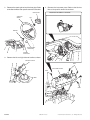
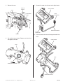
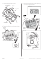
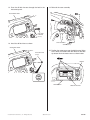
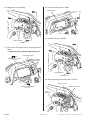
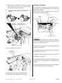
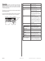
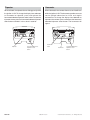
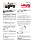
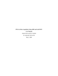
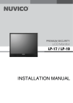
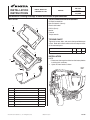
INSTALLATION
INSTRUCTIONS
Accessory
Application
DIGITAL METER KIT
MUV700
Publications No.
MII 12455
Issue Date
P/N 08E80-HL1-100
July 2008
Honda Dealer: Please give a copy of these instructions to your customer.
PARTS LIST
TOOLS AND SUPPLIES REQUIRED
Phillips® screwdriver
Box-end wrench (10 mm)
Electric drill motor
Drill bit (5 mm)
Marker
Fretsaw
Torque wrench
(7)
(5)
TORQUE CHART
Tighten all screws, bolts, and nuts to their specified torque
values. Refer to the Service Manual for the torque values
of the removed parts.
Item
6 mm screw
N·m
kgf·m
Ibf·ft
9
0.9
6.5
(1)
INSTALLATION
NOTE:
• Disconnect the negative cable from the battery before
installing this accessory.
1. Open the front hood as shown.
(6)
FRONT
HOOD
(3)
(4)
(2)
No.
Description
Qty
(1)
Digital meter
(2)
6 mm screw
3
(3)
Collar
3
(4)
Meter sub-harness
1
(5)
Meter cover
1
(6)
6 mm flange nut
3
(7)
Clip
4
© 2008 American Honda Motor Co., Inc - All Rights Reserved.
1
08E80-HL1-1000-91
1 of 10
2. Remove the steering wheel and the lever grips. Refer
to the Service Manual for specific removal instructions.
4. Remove the instrument panel. Refer to the Service
Manual for specific removal instructions.
CENTER PAD
STEERING
WHEEL
Disconnect the vehicle’s connector.
NUT
WASHER
DRIVE SELECT
LEVER GRIP
CHANGE
LEVER GRIP
3. Remove the left and right side net buckle as shown.
SIDE NET BUCKLE
BOLT
INSTRUMENT PANEL
BOLT
BOLT
BOLT
2 of 10
08E80-HL1-1000-91
© 2008 American Honda Motor Co., Inc - All Rights Reserved.
5. Remove the case.
7. Connect the meter sub-harness to the digital meter.
WIRE TIE
Remove.
CASE
DIGITAL METER
10-PIN
CONNECTOR
INSTRUMENT
PANEL
METER SUB-HARNESS
21-PIN
CONNECTOR
SCREW
8. Pass the meter sub-harness through the hole of the
case.
6. Cut out the case as shown. Remove any burrs from
the edges of the hole.
DIGITAL METER
CASE
CASE
FRETSAW
Cut along the marked line.
METER SUB-HARNESS
© 2008 American Honda Motor Co., Inc - All Rights Reserved.
08E80-HL1-1000-91
3 of 10
9. Assemble the digital meter as shown.
11. Cut out the instrument panel as shown. Remove any
burrs from the edges of the hole.
6 mm FLANGE NUT
COLLAR
Cut out area
DIGITAL METER
FRETSAW
Cut out.
CASE
6 mm SCREW
10. Remove the diff lock lens and harness as shown.
DIFF LOCK
HARNESS
Inner side
DIFF LOCK
LENS
FRETSAW
Cut along the marked
line.
4 of 10
08E80-HL1-1000-91
© 2008 American Honda Motor Co., Inc - All Rights Reserved.
12. Pass the diff lock harness through the hole in the
instrument panel.
14. Reinstall the case assembly.
INSTRUMENT PANEL
DIFF LOCK
HARNESS
(Reuse)
CASE ASSEMBLY
13. Install the diff lock lens as shown.
SCREW (Reuse)
INSTRUMENT PANEL
DIFF LOCK LENS
(Reuse)
15. Position the meter cover over the digital meter. Make
sure it does not interfere with the recess or the odo/
trip button. Mark the meter cover as shown below.
MARKER
RECESS
METER COVER
© 2008 American Honda Motor Co., Inc - All Rights Reserved.
08E80-HL1-1000-91
ODO/TRIP BUTTON
5 of 10
16. Remove the case assembly.
18. Install the meter cover as shown.
METER COVER
CLIP
19. Reinstall the case assembly.
CASE ASSEMBLY
SCREW
17. Drill at the marked point of the instrument panel as
shown.
• Remove any burrs from the edge of the hole.
INSTRUMENT PANEL
ELECTRIC DRILL MOTOR
(5 mm BIT)
MARK
CASE ASSEMBLY
SCREW (Reuse)
20. Secure the meter sub-harness with a wire tie.
WIRE TIE (Reuse)
MARK
ELECTRIC DRILL MOTOR
(5 mm BIT)
METER SUB-HARNESS
CASE
ASSEMBLY
6 of 10
08E80-HL1-1000-91
© 2008 American Honda Motor Co., Inc - All Rights Reserved.
21. Reinstall the instrument panel. Connect the meter
sub-harness to the vehicle’s harness. Reconnect all
previously disconnected connectors.
Secure the vehicle’s connector and meter-sub
harness.
Indicators & Displays
The indicators and displays on your vehicle keep you
informed, alert you to possible problems, and make your
riding more enjoyable.
Refer to the indicators frequently. Their functions are
described on the following pages.
4WD indicator
Neutral
indicator
High coolant
temperature indicator
Reverse indicator
PGM-FI indicator
Multi-function
display
VEHICLE’S
10-PIN METER SUBCONNECTOR HARNESS CONNECTOR
hourmeter/odometer/
tripmeter select button
Lamp Check
The High Coolant Temperature indicator and PGM-FI
indicator come on for a few seconds and then go off when
you turn the ignition switch ON.
HARNESS
Install on the case assembly.
22. Secure the harness with a clip.
CLIP (Reuse)
Install on the
case assembly.
The indicators are identified in the table on page 8 with
the words: Lamp Check.
The Reverse indicator comes on and stays on when the
transmission is in reverse.
The Neutral indicator comes on and stays on when the
transmission is in neutral.
The 4WD indicator comes on and stays on when the drive
mode lever is in the 4-wheel-drive rear differential lock
position.
If one of these indicators does not come on when it should,
have your Honda dealer check for problems.
23. Reinstall the left and right side net buckles.
24. Reinstall the steering wheel and lever grips.
© 2008 American Honda Motor Co., Inc - All Rights Reserved.
08E80-HL1-1000-91
7 of 10
Display Check
When the ignition switch is turned ON, the multi-function
display will temporarily show all the modes and digital
segments so you can make sure the liquid crystal display
is functioning properly.
The displays are identified in the table on page 8 with the
words: Display check.
Reverse indicator
Lights when the transmission is in
reverse. Lamp Check.
Neutral indicator
Lights when the transmission is in
neutral. Lamp Check.
4WD indicator
Lights when the drive mode is in the
4WD mode. Lamp Check.
High coolant temperature
Lights when coolant temperature is
indicator
high enough to adversely affect the
service life of the engine.
If the high coolant temperature
indicator comes on while you are
driving, immediately bring the vehicle
If any part of these displays does not come on when it
should, have your Honda dealer check for problems.
to a stop, turn the engine off and let it
cool. Lamp Check.
PGM-FI indicator
Lights when there is any abnormality in
the PGM-FI (Programmed Fuel
Injection) system. Should also light for
Multi-function
display
a few seconds and then go off when
the ignition switch is turned ON. If the
indicator comes on at any other time,
reduce speed and take your vehicle to
a Honda dealer as soon as possible.
Speedometer
Lamp Check.
The display includes the following
functions. Display Check.
Shows the gear position.
Lights when specified maintenance
interval for engine oil change is
reached.
Shows driven speed in miles per hour.
Odometer
Shows the total miles driven.
Tripmeter
Shows the number of miles driven
Multi-function display
Gear position indicator
Oil change indicator
since you last reset the meter.
Hourmeter
Shows hours and tenths of hours of
engine operation.
Hourmeter/odometer/
Selects display of the odometer,
tripmeter select button
tripmeter, or hourmeter. Resets the
tripmeter to zero (0). This button also
used to reset the oil change indicator.
8 of 10
08E80-HL1-1000-91
© 2008 American Honda Motor Co., Inc - All Rights Reserved.
Multi-function Display
Oil change Indicator
The multi-function display includes the following functions:
• Gear position indicator
• Oil change indicator
• Speedometer
• Odometer
• Tripmeter
• Hourmeter
The oil indicator appears in the display when the mileage
or operating hours on your vehicle approaches the oil
change interval specified the maintenance schedule.
Oil change indicator
Gear
position
indicator
Multi-function
display
The oil change indicator comes on at 100 miles (or 20
operating hours) at the initial time, and it comes on every
600 miles (or 100 operating hours) at the second or
subsequent time.
Reset the indicator after each oil change.
To reset the indicator, press and hold the hourmeter/
odometer/tripmeter select button and turn the ignition
switch to ON for more than 2 seconds. The indicator will
disappear.
If the oil is changed before the oil change indicator
appears, be sure to reset the oil change indicator after
changing the oil. The indicator will appears for 2 seconds,
then disappear. This means the indicator is reset.
Odometer/
Tripmeter/
Hourmeter
Oil change indicator
Gear Position Indicator
The gear position indicator shows the gear position when
the ignition switch is in the ON position.
The indicator displays: N for neutral, R for reverse, and D
for drive.
“ - ” will be displayed on the gear position indicator when
the transmission is not shifted into gear properly. Before
driving, check that the gear position is displayed on the
gear position indicator.
Hourmeter/Odometer/
Tripmeter select button
Odometer
If the gear position indicator shows “ - ” and blinks, turn
the ignition switch to the OFF position, and then turn it
back to the ON position again. If the gear position indicator
still shows “ - ” and blinks, see your Honda dealer.
When selected, the odometer registers total distance
traveled in miles while the ignition is ON. To change the
display from tripmeter or hourmeter to odometer, press
and release the hourmeter/odometer/tripmeter select
button.
Gear position
indicator
Odometer
© 2008 American Honda Motor Co., Inc - All Rights Reserved.
08E80-HL1-1000-91
Hourmeter/Odometer/
Tripmeter select button
9 of 10
Tripmeter
Hourmeter
When selected, the tripmeter shows mileage per trip while
the ignition is ON. To change the display from odometer
or hourmeter to tripmeter, press and release the
hourmeter/odometer/tripmeter select button. To reset the
tripmeter to zero, press the hourmeter/odometer/tripmeter
select button and hold it in for at least 2 seconds.
When selected, the hourmeter shows accumulated hours
while the ignition is ON. The hourmeter provides accurate
service period information for initial and regular
maintenance. To change the display from odometer or
tripmeter to hourmeter, press and release the hourmeter/
odometer/tripmeter select button. The hourmeter will
appear.
Tripmeter
10 of 10
Hourmeter
mark
Hourmeter/Odometer/
Tripmeter select
button
Hourmeter
08E80-HL1-1000-91
Hourmeter/Odometer/
Tripmeter select
button
© 2008 American Honda Motor Co., Inc - All Rights Reserved.