1
IPRifAM
FOURTEEN INCH
WINCHESTER
DISK DRIVES
OEM/SERVICE MANUAL
Mt\RCH 15J 1982
* * * * * * *
:~
R
ELI MIN ARY
* * * * * * *
.:REV~SED
September 20, 1982
PRIAM
14-INCH WINCHESTER DISC DRIVES
FIELD SERVICE MANUAL
~RCH
15J 1982
* * * * * * *
PRE LIM I NARY
* * * * * * *
REVISED
September 20, 1982
PRIAM 14" Disc Drives
Field Service Manual
December 21, 1981
PREFACE
This manual has been prepared for the benefit of field service personnel
who are directly involved with the installation and maintenance of PRIAM
14-inch disc drives.
It may also contain information helpful to the OEM
manufacturer of products containing these drives.
In producing this manual, PRIAM has sought to provide enough information to
enable the following field operations to proceed smoothly and efficiently:
Preparation, including provision for compatibility of related
equipment, proper power, and cabling.
Installation and initial testing.
Fault isolation to the assembly level.
Assembly replacement.
The manual contains enough theory of operation to give the reader a general
background on how the drive works. This is intended solely to provide a
context for the testing and troubleshooting procedures. It is not intended
that the manual should enable the reader to do detailed intra-board
troubleshooting or board repair.
i
PRIAM 14" Disc Drives
Field Service Manual
December 21, 1981
TABLE OF CONTENTS
Page
Section
1
GENERAL INFORMATION
1•1
1 .2
1 .3
1 .3. 1
1.3.2
1 .4
1 .4. 1
1 .4.2
FEATURES
SPECIFICATIONS
CONFIGURATION
Physical Configuration
Functional Organization
OPTIONS
Interface Options
Interface Cables and Terminators
Power Supplies and Cables
Mounting Hardware
1 .4.3
1 .4.4
2
INSTALLATION
2. 1
2.2
2.3
2.4
2.5
2.6
2.7
2.8
2.9
2.10
2. 11
2.12
2.13
UNPACKING
VISUAL INSPECTION
JUMPERS
SWITCH SETTINGS
MOUNTING
GROUNDING
CABLING
UNLOCKING
PERFORMANCE CHECK
LOCKING
REPACKING
STORAGE
SHIPPING
3
3.1
OPERATING PROCEDURES
3.2
3.3
4
4.1
4.2
4.3
4.4
4.5
4.6
4.7
SPINDLE AND HEAD LOCKS
POWERING UP/DOWN
PERFORMANCE CHECK
ASSEMBLIES
OVERVIEW
HEAD DISC ASSEMBLY
PHOTOCELL ASSEMBLY
MOTOR CONTROL ASSEMBLY
MAIN PCB
POWER SUPPLY
FRAME ASSEMBLY
ii
PRIAM 14" Disc Drives
Field Service Manual
Page
Section
5
5.1
5.2
5.3
5.4
5.5
5.6
5.7
December 21, 1981
FORMATS
OVERVIEW
SERVO SURFACE
SERVO PATTERN
SERVO SURFACE
SERVO PATTERN
DATA SURFACE
SECTOR FORMAT
NON-QUADRATURE
NON-QUADRATURE
QUADRATURE
QUADRATURE
6
ELECTRICAL CIRCUIT OPERATION
6 •1
6.2
6.3
6.4
6.5
6.6
6.7
6.8
6.9
OVERVIEW
DRIVE SELECTION
POWER UP/DOWN SEQUENCES
MOTOR CONTROL CIRCUITRY
SEEK MODES
SERVO CIRCUITS
DATA READ/WRITE FUNCTIONS
PLO/VFO
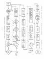
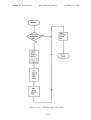
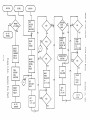
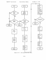
MICROPROCESSOR FLOW CHARTS
7
TROUBLE SHOOTING PROCEDURES
7.1
7.2
7.3
7.4
7.5
FIELD ADJUSTMENTS AND PREVENTIVE MAINTENANCE
GENERAL INSPECTION
STATUS AND ERROR CODES
SYMPTOMS AND CAUSES
SEEK ERRORS AND FAULT CONDITIONS
8
ASSEMBLY REPLACEMENT PROCEDURES
8.1
8.2
8.3
8.4
8.5
8.6
PRECAUTIONS
HEAD DISC ASSEMBLY
PHOTOCELL ASSEMBLY
MOTOR CONTROL ASSEMBLY
MAIN PCB
POWER SUPPLY
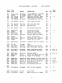
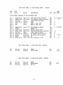
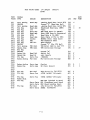
9
SPARE PARTS LIST
10
PRIAM INTERFACE
10.1
10.2
10.3
10.4
10.5
10.6
10.7
10.8
OVERVIEW
CONNECTORS AND PIN ASSIGNMENTS
INTERFACE SIGNAL DESCRIPTIONS
INTERFACE DC CHARACTERISTICS
INTERFACE TIMING
USER-ACCESSIBLE REGISTERS
COMMANDS
REGISTER BIT DEFINITIONS
11
SMD INTERFACE
11.1
11.2
11.3
11.4
11.5
OVERVIEW
CONNECTORS AND PIN ASSIGNMENTS
INTERFACE SIGNAL DESCRIPTIONS
INTERFACE DC CHARACTERISTICS
INTERFACE TIMING
iii
PRIAM 14" Disc Drives
Field Service Manual
December 21, 1981
LIST OF FIGURES
Page
Figure
Title
1.3-1
1.3-2
Physical Configuration of a PRIAM 14-inch Disc Drive
Simplified Block Diagram of a PRIAM 14-inch Disc Drive
2.4-1
2.4-2
2.4-3
2.8-1
Main PCB
Main PCB
Main PCB
Location
5.1-1
5.3-1
5.5-1
Servo and Data Surfaces
Servo Track Signals
Non-Quadrature
Servo Track Signals -- Quadrature
6.1-1
6.4-1
6.6-1
6.7-1
6.7-2
6.7-3
Simplified Block Diagram of a PRIAM 14-inch Disc Drive
Motor Controller
Servo Circuitry
Read/Write Timing and Encoding
Data Write Circuitry
Data Read Circuitry
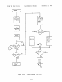
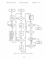
6.9-1
6.9-2
6.9-3
6.9-4
6.9-5
6.9-6
6.9-7
6.9-8
6.9-9
6.9-10
6.9-11
Initialization Flow Chart
Idle Flow Chart
Command Detect Flow Chart
Sequence Up Flow Chart
Sequence Down Flow Chart
Restore Flow Chart
Seek Operation Flow Chart
Track Crossing Flow Chart
Land and On Track Flow Chart
Seek End Flow Chart
Fault Reset Flow Chart
10.4-1
10.4-2
10.4-3
10.4-4
10.4-5
10.5-1
10.5-2
10.5-3
10.5-4
10.5-5
10.5-6
10.5-7
10.5-8
10.5-9
DBUS Transceiver
Single End Line Receiver Gated by DRIVE SELECT
Single End Line Receiver
Single End Line Driver
Differential Line Drivers and Receivers
Register Load Timing
Register Read Timing
Reset Timing
INDEX and SECTOR MARK Timing
WRITE DATA and WRITE CLOCK Timing
READ DATA and READ CLOCK Timing
Record Writing Timing
Record Reading Timing
Read and write Transitions During Gaps
(PRIAM Interface, "B" Drive)
(SMD Interface)
(B-4 Interface)
of Head and Spindle Locks
iv
PRIAM 14" Disc Drives
Field Service Manual
December 21, 1981
Page
Figure
Title
11.4-1
11.4-2
11.4-3
11 .5-1
11.5-2
11.5-3
11.5-4
11.5-5
11.5-6
11.5-7
11.5-8
Typical Read/Write Data and Clock Transmitter and Receiver
Control Line Transmitter
Control Line Receiver
Tag and Bus Timing
Typical Read Timing
Typical Read Control Timing
Typical Write Control Timing
Index and Sector Mark
Drive Select Timing
NRZ Data and Read Clock Timing
Recommended Sector Format
LIST OF TABLES
Table
Title
1.2-1
Specifications for PRIAM 14-inch Disc Drives
2.4-1
Switch Settings on the Main PCB
10.2-1
10.3-1
10.3-2
10.4-1
10.4-2
10.4-3
10.4-4
10.4-5
10.4-6
10.5-1
10.5-2
10.5-3
10.5-4
10.5-5
10.5-6
10.5-7
10.5-8
10.6-1
10.7-1
10.7-2
10.8-1
10.8-2
Interface Connector
Head Selection
Drive Fault Conditions
DBUS Transceiver DC Characteristics
Single End Line Receiver Gated by DRIVE SELECT
DC Characteristics
Single End Line Receiver DC Characteristics
Single End Line Driver DC Characteristics
Differential Line Receiver DC Characteristics
Differential Line Driver DC Characteristics
Register Load AC Characteristics
Register Read AC Characteristics
Reset AC Characteristics
INDEX and SECTOR MARKAC Characteristics
WRITE DATA and WRITE CLOCK AC Characteristics
READ DATA and READ CLOCK AC Characteristics
Record Writing Control AC Characteristics
Record Reading Control AC Characteristics
Register Selection
Command Code Summary
Drive ID Assignments
Status Register Bit Definitions
Address Register Bit Definitions
11 .2-1
11.2-2
11.2-3
Tag Bus I/O Interface ("A" Cable)
Tag Bus Decode ("A" Cable)
"B" Cable Interface
v
Field Service Manual
PRIAM 14" Disc Drives
December 21, 1981
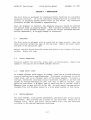
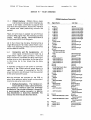
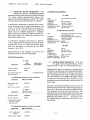
SECTION 1 - GENERAL INFORMATION .
PRIAM 14-inch Winchester disc drives are available in three models,
providing a range of storage capacities, as shown in the following table:
Model Number
1.1
Megabytes
Discs
Data Heads
Tracks/Inch
DISKOS
3350
34
3
480
DISKOS
6650
68
3
960
DISKOS 15450
158
7
960
2
FEATURES
The advantages offered by the 14-inch family of disc drives include:
1.
High Storage Capacity
2.
Low Cost per Megabyte
3.
High Performance
4.
High Reliability
5.
Relatively Small Size
6.
Universal Power Compatibility
7.
Ease of Interfacing
The above advantages are achieved through a combination of design features,
as described in the following paragraphs:
1.
High storage capacity is achieved by using the larger (14")
disc size, in conjunction with high recording and track
densitites.
2.
Low cost per megabyte is achieved by using efficient and
cost-effective methods throughout the entire design,
manufacturing, and marketing process.
3.
High performance is achieved through the use of fully
servoed, linear voice coil head positioning.
This makes
possible the high precision and stability needed in order to
utilize the higher recording and track densities. It also
enables the fast access times necessary for efficient use of
the larger data bases.
4.
High reliability is achieved through the use of a fully
sealed, positive pressure air filtering system, servoed
spindle speed and head positioning systems, cast metal head
disc assembly, efficient cooling system, and microprocessor
implementation of control functions.
1- 1
PRIAM 14" Disc Drives
1.2
Field Service Manual
December 21, '1981
5.
Overall size is kept small by designing the various
assemblies in the proper relationships to one another.
The
(optional) power supply is designed so that it can fit inside
the standard frame. Thus a PRIAM 14-inch disc drive with the
power supply included does not require much more space than a
standard size 8-inch drive with a separate power supply. All
three drives in the PRIAM 14-inch family have identical
overall dimensions. Standard rack mounting can be used.
6.
Power compatibility is assured through the use of all DC
components, including a DC spindle motor. Even when the
built in power supply option is selected, PRIAM drives can
still be used anywhere in the world, since the power supply
input can be strapped to accomodate any of the prevailing
I ine voltages.
7.
Ease of interfacing is assured by the availability of several
different interfaces, including a PRIAM standard interface, a
PRIAM SMD interface, and an ANSI interface. Each of these
has been designed in relation to an entire class of existing
computer hardware.
Virtually any bus now in use can be
accomodated by one PRIAM interface or another.
See the
section on Options (below) for a complete listing.
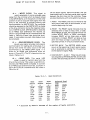
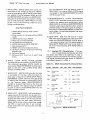
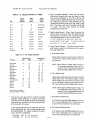
SPECIFICATIONS
Table 1.2-1 summarizes the operating characteristics, physical
characteristics, and power requirements for the three drives in the PRIAM
14-inch family.
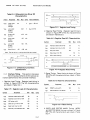
1.3
1.3.1
CONFIGURATION
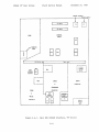
Physical Configuration
Figure 1.3-1 shows the overall physical configuration for the DISKOS 3350,
6650, or 15450.
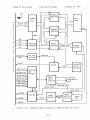
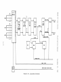
Functional Organization
Figure 1.3-4 is a simplified block diagram showing the relationships among
the major functional units in a PRIAM 14-inch disc drive.
1-2
Table 1.2-1.
December 21, 1981
Field Service Manual
PRIAM 14" Disc Drives
Specifications for PRIAM 14-inch Disc Drives
OPERATING CHARACTERISTICS
DISKOS 3350
DISKOS 6650
DISKOS 15450
33.9 Mbytes
67.8 Mbytes
158.2 Mbytes
Transfer rate (megabytes/second)
1.04
1.04
1.04
Track-to-track seek time (typical)
8 msec
8 msec
8 msec
Average seek time (typical)
45 msec
45 msec
40 msec
Maximum seek time (typical)
85 msec
85 msec
75 msec
9.7 msec
9.7 msec
9.7 msec
Capacity (unformatted)
Average latency
Tracks per inch
Bits per inch
480
960
960
6430
6430
6430
3
3
7
561
1121
1121
3100
3100
3100
20,160
20, 160
20,160
Number of data surfaces
Number of data cylinders
Nominal RPM
Bytes per track
POWER REQUIREMENTS
Power requirements are the same for all three drives:
Maximum
Typical
+ 24 VDC
(~5%)
7.0 A
6.0 A seeking
4.5 A non-seeking
+ 5 VDC
(~5%)
4.0 A*
1.5 A
-
(~5%)
2.0 A
1 .0 A
(~5%
0.7 A
0.5 A
-
5 VDC
12 VDC
)
* 6.0 A maximum with adapters
DIMENSIONS
physical dimensions are the same for all three drives:
Height
Width
Depth
Weight*
*
6.9
16.6
17.6
20.0
52
55
inches
inches
inches with slides
inches
pounds (3350 and 6650)
pounds (15450)
Includes 18 pounds for power supply.
1-3
Add 6 pounds for slides.
PRIAM 14" Disc Drives
December 21, 1981
Field Service Manual
SPINDLE
LOCK
Lever
Drive
Lever
Drive
Positioned Towards
}
Casting=Spindle Locked
Positioned Away From
Casting=Spindle Unlocked
L
~
Locked
Position
!
~
Figure 2.8-1.
CARRIAGE/HEAD
LOCK
.__
~
J,
Location of Head and Spindle Locks
17 56
WI SLIDE OrTION
16.56
[
4 2S
I
2.
C
Zc
BACK
r OWER
I'LUG-
r
o
25-!~
-=~=!
RIGHT
(POWER SUPPLY OPTION)
8-32 UNC-2B
5..PLACES
SPINDl.E LOCK
CARRIAGE LOCK
BOTTOH
Tor
Figure 1.3-1.
Physical Configuration of a PRIAM 14-inch Disc Drive
1-4
PRIAM 14" Disc Drives
-DRIVE SELECT
-RD
-WR
+ADO
+ADI
Field Service Manual
...
.A
~
[ 8-BIT BUS
(tri-state)
PARALLEL
INTERFACE
(Sequencing t
status and
other circuits)
December 21, 1981
SERVO CIRCUITS
HEAD POSITIONER
1--,....
JII"
",
Select and Control Signals
DISC
DATA READ/WRITE HEADS
t>--J ::0..,0'
SERVO HEAD
~
SERVO READ
I.-
&
.
~
R/W CIRCUITS
SPINDLE ASSEMBLY
(Brushless
DC motor,
speed control
circuits)
-HEAD SELECT
-WRITE GATE
*WRITE CLOCK (NRZ)
*WRITE DATA (NRZ)
-READ GATE
SERIAL
INTERFACE
(Data handling
circuits t Index
and Sector Mark)
*(NRZ) READ CLOCK
*(NRZ) READ DATA
-INDEX MARK
-SECTOR MARKS
(NRZ) WRITE CLOCK
*designates differential signals.
Figure 1.3-2.
Simplified Block Diagram of a PRIAM 14-inch Disc Drive
1-5
PRIAM 14" Disc Drives
1.4
1.4.1
Field Service Manual
December 21, 1981
OPTIONS
Interface Options
The PRIAM 14-inch disc drives are available with a variety of interface
options.
Each of these interface options can be used, without
modification, on any disc drive in the 14-inch family.
All PHIAM
interfaces include on-board data separation.
The standard PRIAM Interface is designed for low cost and for efficient use
with microprocessor-based systems. Up to four drives may be daisy-chained,
when this interface is used. The PRIAM interface provides a basic 8--bit
bidirectional bus, which may be used with the currently popular 8-bit and
16-bit :microprocessors. It also provides bit-serial NRZ data exchange. No
elaborate handshaking protocols are required. The PRIAM interface is built
into the disc drive's main PCB. A 50-conductor flat ribbon cable is used
between the PRIAM interface and the host system.
See the PRIAM INTERFACE
section for more details.
The SMD Interface permits a PRIAM drive to be used with existing Storage
Module Drive (SMD) controllers. In the 14-inch drives the SMD interface is
built into the disc drive's main PCB.
The line drivers and line receivers
in the SMD interface are matched to those of typical SMD controllers.
There are two interface cables between the host system's SMD controller and
the PRIAM disc drive's SMD interface -- a 60-conductor twisted-pair flat
cable ("A" cable) and a 26-conductor flat ribbon cable ("B" cable). See
the SMD INTERFACE section for more details.
The ANSI Interface complies with the disc drive interface standard proposed
by ANSI Technical Committee X3T9.
Characteristics of the ANSI interface
include variable and fixed sector sizes, data transfer rates up to 10
megabits per second, and radial attention and select capability. Up to
eight drives may be daisy-chained, on a single 50-conductor flat ribbon
cable. See the ANSI INTERFACE section for more details.
1.4.2
Interface Cables and Terminators
I/O cables are available from PRIAM, for connecting the user's controller
to the PRIAM disc drive, and for connecting daisy-chained drives to one
another.
Terminators are available for I/O signal lines, to minimize reflections and
to ensure maximum data integrity. One set of terminators is required for a
single drive, or for the base drive in a daisy chain.
1-6
PRIAM 14" Disc Drives
1.4.3
Field Service Manual
December 21, 1981
Power Supplies and Cables
PRIAM's optional power supply allows PRIAM disc drives to operate from 100,
120, 220, and 240 VAC, 50 or 60 Hz power. The optional power supply is
delivered already mounted within the drive frame.
No extra space or
interconnection is required.
1.4.4
Mounting Hardware
Optional slides are available from PRIAM.
These slides allow easy access
to drives mounted in standard racks and cabinets.
1-7
PRIAM 14" Disc Drives
Field Service Manual
December 21, 1981
SECTION 2 - INSTALLATION
The disc drive is packaged to withstand normal handling in a reusable
shipping container. It is the customer's responsibility to notify the
carrier if shipping damage should occur to the drive.
Any insurance
protection is also the customer's responsibility.
When the shipment is received, the shipping container should be examined
for obvious signs of shipping damage.
Most insurance adjusters require an
inspection of the damaged container. Notify the carrier and PRIAM Customer
Service immediately, if shipping damage is discovered.
2.1
UNPACKING
The disc drive is shipped with an outer and an inner carton. Open the
outer carton by cutting the tape on the top side.
Remove the inner carton
and open it by cutting the tape.
Remove the disc drive from the carton and place it on a clean, flat work
surface. Remove the wrap.
2.2
VISUAL INSPECTION
Visually inspect the drive for loose, bent, or broken parts.
damage to the carrier and to PRIAM Customer Service.
2.3
Report any
POWER SUPPLY SETUP
If a PRIAM optional power supply is present, check the AC voltage selection
circuit board prior to applying power. This board is adjacent to the AC
input plug, and is an integral part of the power supply.
To select a
voltage, remove the selection circuit board and reinsert it so that the
proper AC voltage designation (100, 120, 220, or 240) is visible. Also
check the fuse value. A 5 ampere fuse is used with 100 or 120 VAC, while a
Z.5ampere fuse is used with 220 or 240 VAC. No modification is required for
changing from a 60 Hz power source to a 50 Hz power source, or vice versa.
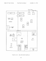
2.4
SWITCH SETTINGS
The drive address, write protect parameters, and sector size are all switch
selectable.
The switches are located on the main PCB.
Referring to
Figures 2.4-1, 2.4-2, and 2.4-3, and to Table 2.4-1, set the switches
according to the desired operating condit~ons.
2-1
December 21, 1981
Field Service Manual
PRIAM 14" Disc Drives
MOTOR CONTROL
PO\o,TER SUPP1.¥
t
I
C
C
I
I
I
II
I
OPEN
~-j--.,
r-----,
,
I
II J4 I:
31 DATA
I
L
,
I
: J3
:
I
L
-',
I
~
32 DATA
CONTROL
LOGIC
I
I
~
I
I
I
I
I
MARKING
______ /
~
o
~
I
AREA
!
I
;,"
I
I
------ ~
I
C,-/
/
",'
,,'
B
BEJ
/)
,,"
DIVISION BAR
"NOT GND"
:
,..---------"'1
I
I
I
I
:
DATA
PLO
I
:
JI
~
WINDOW
ADJUST
r- --------,
I
I
I
:
I
P.O.R.
POWER/
:L
RESET
I
:
oJ:
I
I
I
I
I
,..----------1
I
I
:
I
I
VFO
I
INDEX
I
:
l__ ---------1I
SERVO
CIRCUITS
&
I
I
READ
&
WRITE
CIRCUITS
Figure 2.4-1.
GUARDBAND
I
I
I
CIRCUITS
1 I
L.
R!W
SERVO
Bt]
r-- - - - - - - - - - - - - -
I
I
I
I
I
I
Main PCB (PRIAM Interface, "B" Drive)
2-2
SERVO
POWER
AMP
PRIAM 14" Disc Drives
Field Service Manual
December 21, 1981
MOTOR CONTROL
I
POWER SUPPLY
t
_~
D_ATA .19
~l
DATA Jl
l -.,
r--
: Jl~ :
L~_J
: J3
,
L..-_ _
!'
J
DATA J2
CONTROL
PANEl
.
r-=l
J8
B
~
INTERFACE
B
-----1
"'l
("';
o
I
a . - - MARKING
I
AREA
I
___J
I
B
8
DIVIDER BAR
,
I
8
DATA
WINDOW
ADJUST
R32
r-----,
~-------,
:
I
, PLO
1-.___
,
,
,:
'
,
I
,
:
:
:
I
I
P.O.R.
POWER/
RESET
~----------
I
:
:
:
.
I
I
r
I
I
I
I
VFO
1
INDEX
,
&
SERVO
,
I
CIRCUITS
,
~-----~1
GUARDBAND
I
,,
,
t
READ
CIRCUITS
I
L-1 s~,~o
&
WRITE
CIRCUITS
I
r------
I
I
I
I
I
BE]
Figure 2.4-2.
,!~
I
I
I
Main PCB (SMD Interface)
2-3
,..-- - -- -- -----:
:
I
SERVO
PO\\!ER
ANP
Field Service Manual
PRIAM 14" Disc Drives
December 21, 1981
MOTOR CONTROL
I
pm,TER SUPPl
C
C
J9 DATA
o
CONTROL
PANEL
r
I
J1 DATA
lL.
I
.JI
READY
EJ
o FAULT
EJ
B
-----"1
8
I
J3 :
J2 DATA
INTERFACE
"%j
J--,
I
,
l..-- MARKING
~:
AREA
1
------_-1
PARTITIO~
BAR
I
I
I
r---------l
I
,
I
,
:
DATA
WINDOW
ADJUST
PLO
r--------,
P.O.R.
I
:
:
:
It------
IL
I
.I
POhTER/
:
RESET
J:
I
I
,
I
I
,..----------1
I
I
:
,
,
I
I
VFO
INDEX
:
SERVO
I
I
L-----------l
&
CIRCUITS
I
I
READ
GUARDBAND
,
I
I
I
&
I
WRITE
ILJ
CIRCUITS
Figure 2.4-3.
R/w
SERVO
I
r- ---- - __ J
,
GB
Main PCB (B-4 Interface)
2-4
I~-----------------
I
SERVO
I
pm,'ER
I
AHP
I
I
15450 SPLIT
I:~f
December 21, 1981
Field Service Manual
PRIAM 14" Disc Drives
PRIAM
200208
~
~
13
: W1
J
d
t;f
9F
•
W2 •
15450 SPLIT
C3
off
2E
•
• WI
0
~
~
SMD
200218 & 200263
J
J
~
off
10E
Ba aC
~ ••
W3
••
W2
2-4.1
W4
•
A
IT]
to
~
~
.....
15450-10
SWITCH LOCATION
15450-20
IJ
~
~
~
....o
2E
(I)
1
DEVICE SELECT 1
o
DEVICE SELECT 1
~
roo--
z
0
H
ti
~
z
N
2
2
3
3
4
<4
4
8
••
w
(I)
....
"'Ij
roo--
6
V1
J:'-
-
V1
0
tJ)
1
I
....11
<
(t)
5
p::
w
2
-
~
o
tv
-0
f-'
~
6
SWITCH
ON-WRITE PROTECT
10E
9F
LOCATION
I
'I
-2
3
z
1
I
16
1
,
I
~
V1
16
I
I
2
4
4
8
5
16
I
.
I
I
I
0
32
2
64
4
,
I
32
I
64
..... _n
EB-~
> .......>
u
(t)
128
8
I
128
256
16
,
256
(JQ
tJ
5
~
~
w
~
;.:l
z
-----.
I
I
6
1
8
32
64
I
I
I
I
512
32
1024
64
OFF"SECTOR/TRACK
ONE BYTES/SECTOR
I
,,
I
I
512
102~
UFF"'SI:;CTlJR/TKACK
ON"'BYTES/SECTOR
0
~
"d
~
~
~
n
H
(t)
OJ
0
..
en
11
<
....
Of-'
~
I
~
..,.
>
;:l
~
N
(t)
0,
tv
0
0
tv
::s
~
~
I:;
0
Q
(t)
0
(t)
-:8
w-...I
g.
(t)
11
t-J
.
~
~
\0
ex>
PRIAM 14" Disc Drives
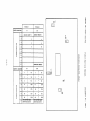
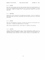
Table 2.4-1.
Note:
December 21, 1981
Field Service Manual
Switch Settings on the Main PCB
"B" Level Drive with PRIAM Interface
Switch Group Location on PCB
Switch #
11K
10K
in Group
1 sector/track
Drive Select 1
1
16 bytes/sector
2 sectors/track
Drive Select 2
2
32 bytes/sector
4 sectors/track
Drive Select 3
3
64 bytes/sector
8 sectors/track
Drive Select 4
4
128 bytes/sector
Skip Defect Prot.
16 sectors/track
5
256 bytes/sector
On = Protected
Write Enable
32 sec"tors/track
6
512 by"tes/sector
All Heads
Write Clock
64 sectors/track
7
Off=Open
1024 bytes/sector
On=Closed
Write Clock
8
Off=Normal
See Note Below
On=Inverted
When Switch 8 is Off, Switches 1-7 select sectors/track.
When Switch 8 is On, Switches 1-7 select bytes/sector.
Switch #
in Group,
SMD Interface
Switch Group Location on PCB
10N
12K
:zq r0
1
Drive Select 1
1 sector/track
2
Drive Select 2
2 sectors/track
2ocf~
3
Drive Select 4
4 sectors/track
/Oztf
.....
4
Drive Select 8
8 sectors/track
~ J
Z-
Z;~
5
Reserved
16 sectors/track
6
Reserved
32 sectors/track
h4
7
Reserved
64 sectors/track
3Z-
8
Write Protect
All Heads
2-5
Off
jZ
Ib
l b '{(,
:z..
\
u'~
~
Or=p
(.>~
~
"3
z
L>6 )
December 21, 1 ';I~I
Field Service Manual
PRIAM 14" Disc Drives
MODEL NUMBER
3150-10
6650-10
6650-20
3350-20
,.
PCBA NUMBER
oo~
WI
0
H 00
E-iH
W2
z~
. W3
u
ZE-i
z
ii:~
::c:
~u
~
W4
0
W5
~
0000
::;::lH
u
o~
.
Z
0
H
E-i
I
P:::l
~~
~
::;::l..-J
0P:::l
P:::l
I
e"E-i
U
•
<r.:
E-i~
U..-J~
::;::l~..-J
0
Z
~~
~
OOOZ
0
000
~ ~ ~
00
H
::c:
E-i
W7
0
p;:::<r.:
~
W6
U
Z
E-i
<t
u
~ H
IJ P;::: ~
~
Wl:x-. H
IX ~
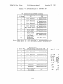
200173-01
".,
*
*
*
*
A-B
*
W8
A-B
W9
WI 1
*
*
A-B
WI2
B-C
WI3
WI0
O<:~ofC
W14
*
*
N
W15
A-B
WH:'
A-B
WI7
A-B
Z
..
w
E-i
0
Z
..
~
E-i
0
Z
200113
200173-02
*
*
*
*
*
*
*
*
*
*
200088
*
*
*
*
*
*
*
*
*
*
*
*
*
*
*
B-C
*
B-C
*
*
PCBA NUMBER
-.
WI
200208
WRITE PROTECT
Z
~-C
*
*
*
200148-02
A-B
*
*
*
B-C
B-C
*
*
*
*
*
*
*
*
*
*
R-C
A-B
B-C
A-B
B-C
A-B
*
*
A-B
B-C
A-B
B-C
B-C
A-B
B-C
R_r
B-C
R-r
INSTALLED
A-B
MODEL NUMBER
15450-10
200148-01
OPEN
I
15450-20
200218/200263
"OR INDEX & SECTOR
WITH READ GATE
H
~
~Z
~~
zu
~§
~~
~c
::;::lZ
IJ<
f/)
or-l
W2
J-I
Q)
SKIP DEFECT RECORD ENABLE ADDRESS MARK
NOT PROTECTED
JUMPER SELECTION CHART
l:l.
S
;:l
IJ
W3
ENABLE LONG RESET
~
Q)
~
'-'
W4
15450 Analog Split 200213
AUTO SEQUENCE UP
A-B ENABLES CYLINDER
ADDRESS BIT 10
R-r. nT~A'RLE~ RTT 10
Wl,W2,W6 & W7 Installed; W5 B-C position;
2-5.1
PRIAM 14" Disc Drives
2.5
Field Service Manual
MOUNTING
The disc drive may be mounted in a standard 19-inch rack.
slides are present, they may be installed at this time~
2.6
December 21, 1981
If the optional
GROUNDING
"EI"
Ground Strap
Ground Terminal
Screw for mounting
Ground Strap
to VCM
' - - - PCB
VCM
2.7
CABLING
If a separate power supply is used, the power cable should be installed to
connector J3 on the Main PCB.
The DC voltages required at the respective
pins on J3 are listed (below) in the PERFORMANCE CHECK section.
Interface
cables to the host system are described in the sections covering each of
the available interface options. Cabling between assemblies within the
disc drive is completed at the factory prior to shipment.
More details on
inter-assembly cabling are given in the ASSEMBLY REPLACEMENT PROCEDURES
section.
2.8
UNLOCKING
Both the dr i ve spindle and the head carr iage are locked pr ior to
shipment.
After the drive has been completely mounted and cabled, these
must be unlocked to enable normal operation.
The spindle lock and the head carriage lock are both fully accessible on
the bottom of the HDA (Head Disc Assembly). Referring to Figure 2.8-1,
place both levers in the UNLOCK position.
CAtnION:
AVOID MANUAL ROTATION OF THE SPINDLE OR MOVEMENT OF THE
CARRIAGE.
DAMAGE TO THE DISC SURFACE MAY OCCUR IF THE BEADS ARE
MOVED ACROSS A NON-ROTATING DISC SURFACE.
2.9
PERFORMANCE CHECK
Conduct a performance check, as described in the OPERATING PROCEDURES
section.
2-6
PRIAM 14" Disc Drives
2.10
Field Service Manual
December 21, 1981
LOCKING
Both the drive spindle and the head carriage should be locked whenever the
drive is to be physically moved, even if it is not to be shipped. To lock
the drive, refer to Figure 2.8-1, and place both levers in the LOCK
position.
2. 11
REPACKING
Repacking is the reverse of the unpacking procedure. Prior to repacking
the drive, make sure that the spindle and carriage locks are in the LOCK
positions.
2.12
STORAGE
When the environment is severe, or when the drive is to be stored for a
long time, it should be repacked prior to storage.
When storing unpacked drives, avoid dusty or unstable environments.
2.13
SHIPPING
Contact PRIAM Customer Service for a return authorization number prior to
shipping a drive or assembly to PRIAM. After locking the drive spindle and
head carriage, pack the drive in its original carton or an equivalent one.
2-7
Field Service Manual
PRIAM 14" Disc Drives
December 21, 1981
SECTION 3 - OPERATING PROCEDURES
3.1
SPINDLE AND HEAD LOCKS
Before -the drive can be operated, it is necessary to place both spindle and
head lock levers in the UNLOCK position.
Refer to Figure 2.8-1 for the
locations of these levers.
Whenever the drive is to be moved for any reason, the spind1e and
head 10ck 1evers shou1d both be p1aced in the LOCK position.
3.2
POWERING UP/DOWN
The exact procedure for powering up the drive depends on the interface
option present.
If the drive has a standard PRIAM interface, apply DC power,
select the drive (via the -DRIVE SELECT lines) and issue a
Sequence Up command.
If the drive has an SMD interface, apply DC power, select the
drive (via the UNIT SELECT lines), then bring PICK and HOLD to
ground.
If the drive has an ANSI interface, apply DC power, select the
drive (via the
Attn / Select lines, then issue a
Spin Up
command.
If the drive has a BASIC FOUR interface, apply DC power and
select the drive (via the UNIT SELECT lines).
Similarly, the procedure for powering down also depends on the interface
option present:
If the drive has a standard PRIAM interface, issue a Sequence
Down command.
If the drive has an SMD interface, remove the ground from PICK or
HOLD.
If the drive has an ANSI
command.
interface,
issue a Sequence Down
If the drive has a BASIC FOUR interface, remove DC power.
3-1
PRIAM 14" Disc Drives
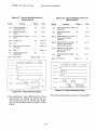
3.3
Field Service Manual
December 21, 1981
PERFORMANCE CHECK
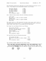
The following procedures are recommended as an initial check for proper
operation of the disc drive:
2.
If any voltages are outside specification, check the corresponding
current demands.
Voltage
Maximum Current
-5 VDC
2.0 amperes
+5 VDC
4.0 amperes for 3350 drive
6.0 amperes for 6650 drive
b.O amperes for 15450 drive
-12 VDC
0.7 amperes
+24 VDC
7.0 amperes from start of spindle rotation
until Ready.
5.0 amperes after Ready.
6.0 amperes after Ready during an active
seek operation.
3.
Power up the drive, as detailed in the POWERING UP/DOWN section,
above.
Spindle rotation should begin.
4.
Watch for the drive to become Ready. If no faults are detected during
the power up sequence, this will take about 60 seconds. If a f aul t
is detected (by the safety circuits within the drive), Ready will be
inhibited and a fault condition will be reported. See the STATUS AND
ERROR CODES section of the TROUBLE SHOOTING PROCEDURES for details.
If, after two minutes, the microprocessor within the drive is unable
to sense that the spindle is rotating at the specified speed, Ready
will be inhibited and spindle rotation will stop.
3-2
PRIAM 14" Disc Drives
5.
December 21, 1981
Field Service Manual
Check the head posi tioning operation by issuing seek commands.
following seek pattern is suggested:
The
From 000 to 001 to 000 to 002 to 000 to 003 to 000 to 004
to 000 to 005 to 000 ••• to maximum cylinder address.
6.
Verify that the average seek time complies with the specification.
This is done by performing a seek between cylinder 000 and a specified
"average" cylinder, and watching for an indication that the seek has
been completed. The cylinder number and the maximum time allowed both
depend on the disc drive type.
The signal line to be monitored
depends on the interface type. The following table gives details:
Drive Type
7.
Cylinder #
Seek Time
DISKOS
3350
187
45 msec
DISKOS
6650
374
48 msec
DISKOS 15450
374
45 msec
Interface Type
Signal Line Monitored
Standard PRIAM
-READY
SMD
ON CYLINDER
ANSI
BUSY
BASIC FOUR
ON CYLINDER
Check for proper data transfer operation by writing and then reading
data with each read/write head.
CAUTION:
WRITE OPERATIONS ALTER PREVIOUSLY RECORDED DATA
Most disc systems require a formatted disc before data transfer can be
performed.
A disc surface defect map is supplied by PRIAM with each disc drive.
The defect map indicates the location of defects discovered during
manufacturing and testing.
A defect location is specified by the
number of byte positions from the index mark.
3-3
PRIAM 14" Disc Drives
Field Service Manual
December 21, 1981
SECTION 4 - ASSEMBLIES
4•1
OVERVIEW
PRIAM disc drives are constructed in a modular fashion, so that defective
assemblies can be easily replaced.
This greatly reduces down time due to
servicing. The six assemblies are:
Head Disc Assembly
Photocell Assembly
Motor Control Assembly
Main PCB
Power Supply
Frame Assembly
The exact procedures for removing and replacing these assemblies are
described in the ASSEMBLY REPLACEMENT PROCEDURES section.
4.2
HEAD DISC ASSEMBLY
The Head Disc Assembly (HDA) is a contamination-resistant enclosure. It
contains the drive spindle assembly, drive motor, voice coil actuator, head
carriage assembly, read/write heads, magnetic disc(s), and air filter
assemblies.
4.3
PHOTOCELL ASSEMBLY
The Photocell Assembly contains three infrared light-emitting diodes and
phototransistors. Its purpose is to monitor and control spindle motor
rotation.
4.4
MOTOR CONTROL ASSEMBLY
The Motor Control Assembly contains the circuitry associated with driving
the spindle motor. This circuitry receives an On/Off command from the Main
PCB, and spindle rotation feedback from the Photocell Assembly.
4-1
PRIAM 14" Disc Drives
4.5
MlUN
Field Service Manual
December 21, '1981
PCB
The main PCB contains all the circuitry associated with head positioning,
read/write control, command execution, and information transfers across the
user interface.
4.6
POWER SUPPLY
If the PRIAM power supply option is chosen, the power supply is mounted
within 1:he Frame Assembly.
The PRIAM power supply can operate from 50 or
60 HZ, with input voltage (selectable) of 100, 120, 220, or 240 VAC.
4.7
FRAME ASSEMBLY
The Frame Assembly is constructed to accomodate all of the standard and
(PRIAM-built) optional assemblies of the disc drive. Its open steel rod
and sheet metal design provides improved air circulation, and also makes
the drive lighter, lower in cost, and easier to install.
4-2
PRIAM 14" Disc Drives
Field Service Manual
December 21, 1981
SECTION 5 - FORMATS
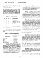
5•1
OVERVIEW
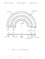
The PRIAM 3350 disc drive has a single disc with two magnetic surfaces.
Each surface accomodates two heads, as shown in Figure 5.1-1.
On the
"bottom" surface, the inner head reads the servo information, and the outer
head writes and reads data surface O.
On the "top" surface the outer head
writes and reads data surface 1, and the inner head writes and reads data
surface 2.
The PRIAM 6650 has exactly the same configuration of disc surfaces and
heads as the 3350, but it achieves twice the storage capacity by having
twice as many tracks per inch.
The PRIAM 15450 has two discs. The configuration of the "lower" disc is
exactly like that of the disc on the 6650. The "upper" disc has four data
heads, which write and read data surfaces 3 through 6.
5.2
SERVO SURFACE -- NON-QUADRATURE
The purpose of the servo surface is to provide a coordinate system by means
of which the electrical circuitry of the disc drive can locate specific
areas for writing or reading data. The servo surface itself is written
once at the factory, and thereafter is a read-only area.
The information
on the servo surface is used to determine the angular position of the disc,
as well as the radial position of the head carriage.
The servo surface for the 3350 is divided into four distinct groups of
tracks.
From the inside (hub) out, these are as follows:
a.
Guardband 3
b.
Servo data band
c.
Guardband
d.
Guardband 2 (landing zone)
22 tracks
7 tracks
45 tracks
Within each of these bands, there are two types of tracks -- odd tracks and
even tracks.
Each track type produces a characteristic signal at the read
head, as described below in the SERVO PATTERN section. If the read head is
closer to an odd track, the odd pattern will have greater amplitude. In
the same manner, the even pattern will have greater amplitude if the read
head is closer to an even track.
The servo circuitry compares the amplitudes of the signals from the
adjacent tracks, and identifies the equal-amplitude condition as a "track
crossing". During seek operations, the servo circuitry counts the track
crossings in order to derive the cylinder address of the data write/read
heads.
During write and read operations, the servo circuitry adjusts the
posi tion of the head carriage in such a manner as to preserve the equalampli tude condition, thus keeping the wri,te/read head "on track".
5-1
PRIAM 14" Disc Drives
Field Service Manual
December 21, 1981
CYLINDER 000
HUB EDGE
+
DATA
BAND 1
DATA BAND
a
HEAD LANDING ZONES
SERVO BAND
Figure 5.1-1.
I
CENTER
POINT
Guardband 1
Guardband 3
Servo and Data Surfaces
5-2
Guardband 2
PRIAM 14" Disc Drives
5.3
Field Service Manual
December 21, 1981
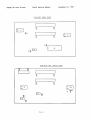
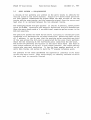
SERVO PATTERN -- NON-QUADRATURE
A variety of bit patterns are written on the servo tracks to identify the
various areas on the servo surface. Figure 5.3-1 shows these patterns.
For each pattern illustrated the figure shows the data written on the odd
tracks and the even tracks, and the composite signal from the servo read
head when it is centered between the two adjacent tracks.
The negative pulses are sync pulses. In the all 0 pattern, these pulses
occur at 2-BYrE' intervals, and serve to define the bit-cell boundaries.
When the servo head reads a 1, an additional negative pulse occurs in the
mid-cell position.
The positive pulses are used by the servo circuitry to recognize track
crossings or to maintain the on-track condi tion. Referring again to the
all 0 pattern, it can be seen that the positive pulse occurring one-third
of the way across the bit-cell is generated by the even track pattern,
while the one occurring at the two-thirds point comes from the odd track.
The first two patterns are written in the servo data band. The bulk of
each track consists of the all 0 (non-index) pattern. The index pattern
occurs only once each revolution.
It has the same angular position on all
servo data tracks, and serves to mark the "0" angular reference point.
The patterns on the three guardbands are repeated at intervals of 512 bytes
around the servo track. They serve simply to identify the band in which
the servo head is currently located.
5-3
Field Service Manual
PRIAM 14" Disc Drives
Non Index
000-560
sync
Odd
o
sync
o
sync
December 21, 1981
o
syr c
...-._ _
0
n ___,S-'
1
1
o
______.J
sync
sync
o
Servo
Index Time
000-560
o
Servo
Guardband 1
Servo
o
___J
Guardband 2
Servo
o
Guardband 3
o
1
1
-fl
Servo
Figure 5.3-1.
Servo Track Signals -- Non-Quadrature
5-4
PRIAM 14" Disc Drives
5 .4
Field Service Manual
December 21, 1981
SERVO SURFACE -- QUADRATURE
The purpose of the servo surface is to provide a coordinate system by means
of which the electrical circuitry of the disc drive can locate specific
areas for writing or reading data. The servo surface itself is written
once at the factory, and thereafter is a read-only area.
The information
on the servo surface is used to determine the angular position of the disc,
as well as the radial position of the head carriage.
The servo surface is divided into four dis1:inct groups of tracks.
inside (hub) out, these are as follows:
From the
a. Ouardband 3
b. Servo Data Bauds
c. Guardband 1
d. Guardband 2 (the Head Landing Zone)
Within each of these bands, there are four types of tracks -- odd normal
tracks, odd quadrature tracks, even normal tracks, and even quadrature
tracks.
Each track type produces a characteristic signal at the servo read
head, as described below in the SERVO PATTERN section.
The closer the
servo read head is to a particular track, the greater will be that track's
contribution to the servo head's output.
The servo circuitry compares the amplitudes of the signals from adjacent
tracks, and identifies an equal-amplitude condition as a "track crossing".
During seek operations, the servo circuitry counts the track crossings in
order to derive the cylinder address of the data write/read heads. During
write and read operations, the servo circuitry adjusts the position of the
head carr iage in such a manner as to preserve the equal-ampli tude
condition, thus keeping the write/read head "on track".
5-5
PRIAM 14" Disc Drives
5.5
Field Service Manual
December 21, '1981
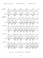
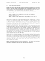
SERVO PATTERN -- QUADRATURE
Figure 5.5-1 shows the four kinds of servo track signals. The normal servo
data patterns are written on the integer tracks, and the quadrature servo
data patterns are written on the half-integer tracks.
The negative pulses are sync pulses.
In the all no" pattern, these pulses
occur at regular intervals, and serve to define the frame boundaries. When
the servo head reads a "1", an additional negative pulse occurs in the midframe position. The frame time interval (T) is equal to 16 write/read data
bit times.
Most of a given track is written with the "0" pattern.
The "1"
pattern occurs once each revolution of the disc, and serves to define the
INDEX location.
The positive pulses are used by the servo circuitry to recognize track
crossings or to maintain the on-track condi tion. Referring again to the
all "0" pattern, i t can be seen that the even normal track generates
positive pulses occurring one-third of the way across the frame, while the
odd normal track generates positive pulses occurring at the two-thirds
point.
The quadrature track patterns have positive pulses alternately at
the one-third and two-thirds positions.
When the servo read head is midway between two adjacent tracks (a "trackcrossing" position) the output resembles the patterns shown at the bottom
of Figure 5.5-1. Successive frames produce the equal-amplitude posi ti ve
peaks, alternating with single large peaks. By analysing which frames have
the equal-amplitude peaks, and whether the large peaks occur at the onethird or the two-thirds locations within the frame, the servo circuitry is
able to determine which of the four kinds of "track-crossing" positions is
being indicated.
Note that the servo read head is midway between two
adjacent~ tracks when the data write/read heads are "on-track".
The servo circui try counts the track crossings in order to determine the
current cylinder address.
In the 3350, data tracks are written at
alternate cylinder address (all integer or all half-interger).
In the
6650 and 1 5450, d at a t r a c k s are w r itt e n at both in t e g era n d ha 1 f - in t e ge r
cylinder addresses.
5-6
PRIAM 14" Disc Drives
LOG1CAl
Field Service Manual
December 21, 1981
.
~_;_'ME_!O_UND_AR_Y--~b~~ o"T"o"~~"rl;~
ODD NORMAL WRITE DATA
.£AD
MelON ODD NORMAL
RiVO
DAC~
ODD QOA.DR.ATUU Vl.IT!
J)A'IA
IUD IACl
~
ODD
QUADRATURE SERVO TlACl
IVEN
IIJl.KALWltITE DATA
EVEN QUADRATURE \.TRITE
DATA
lEAD IACl ON !VEN
QUADRATURE SERVO nACl
n.AD IACl ON DATA TlACl
Jl'NEEN ODD IfJRMAL Am>
IVE N QUAN..ATt1i.! IIiVO nACXS
I.UD IACl ON DAtA nACl .!'TWEEN
IVE N Jl)R.KAL AJro EVE N
QUADRATt1R.! SEIVO nAClS
• ~illin& 'TDc at the fr..e boundary will relult in low .. plitude lim al
• • •bowo at A* aDd ..
Figure 5.5-1.
Servo Track Signals -- Quadrature
5-7
"o"l
PRIAM 14" Disc Drives
5.6
Field Service Manual
December
~1,
1981
DATA SURFACE
The configuration of tracks on the data surfaces has a one-to-one
correspondence with the configuration of servo tracks on the servo surface.
Thus, for example, when the servo head is in the servo data band, all the
wr i te/read heads are in the corresponding posi tions in their respecti ve
write/read data bands.
When the servo head is in the servo landing zone,
each data head is also in its own landing zone.
The write/read data tracks are numbered consecutively, starting with track
o nearest the outside edge of the disc. Each write/read data track is
divided into sectors.
The division of tracks into sectors can be adjus'ted
by the user through switch settings on the main PCB, as detailed in the
INSTALLATION section.
5.7
SECTOR FORMAT
In a typical sector format, each track is divided as follows:
Index Mark
Gap (type 1)
Skip Defect Record
N identical Data Sectors
Gap (type 3)
The index mark is a 1.92 microsecond (two-byte times) pulse,
the index pattern on the servo data surface.
derived from
The type 1 gap allows for VFO synchronization for data separation.
consists of zeros, and has a minimum length of 23 bytes.
It
The composition of the Skip Defect Record and of the N identical Data
Sectors are described below.
The type 3 gap is a function of sector size, and is used to fill (with
zeros) the space left over after the largest possible integer number of
sectors (commensurate with the switch settings) have been written.
It should always be remembered that the switch settings (determining sector
size) are read by the microprocessor as part of the Sequence Up proces s.
Thus, a change in these switch settings will not take effect until the
drive is once again sequenced up, or re-initialized from a power down
condition.
5-8
December 21, 1981
Field Service Manual
PRIAM 14" Disc Drives
The Skip Defect Record can identify up to three defective sectors on the
track. The format for the Skip Defect Record is as follows:
Data sync (FB hex)
1st defect address
2nd defect address
3rd defect address
Check sum
Fill characters (zeros)
1
2
2
2
2
2
byte
bytes
bytes
bytes
bytes
bytes
The N identical Data Sectors have the following structure:
Sector Mark
Gap (type 1 )
Address Field
Gap (type 2)
Data Field
zeros (23 bytes minimum)
zeros ( 11 bytes minimum)
The sector mark is a 960 nanosecond (one byte time) pulse which occurs at
the beginning of each sector.
It is generated by the servo circuitry,
using a byte clock which is initialized by the index pulse.
The format for the Address Field is as follows:
Sync pattern (F9 hex)
Head and high order cylinder address
Low order cylinder address
Sector address
Sector length and flag
CRC
Fill characters (zeros)
1
1
1
1
byte
byte
byte
byte
1 byte
2 bytes
2 bytes
The Data Field has the following structure:
Sync pattern (FD hex)
byte
Data bytes (according to sector length)
CRC
2 bytes
Fill characters (zeros)
2 bytes
The following diagram summarizes the sector format:
f DATA
FIELD
,
L
N
GAP GAP
SKIP GAP ADDRESS GAP
TYPE TYPE DEFECT TYPE FIELD TYPE
RECORD 1
2
3
1
1
INDEX
MARK
DATA
FIELD
GAP ADDRESS GAP
TYPE FIELD TYPE
1
1
SECTOR
MARK
SECTOR
MARK
1
2
5-9
2
2
DATA f
FIELD
2
,
I
PRIAM 14" Disc Drives
Field Service Manual
December 21 ,1981
SECTION 6 - ELECTRICAL CIRCUIT OPERATION
6. 1
OVERVIEW
Figure 6.1-1 is a simplified block diagram of the PRIAM 3350 disc drive
with the standard PRIAM interface.
The overall organization shown is the
same for all drives in the 14" family.
The '15450, however, has two
magnetic discs and seven data heads, rather than "the single disc and three
data heads.
Also the names of the specific interface
signals vary as a function of the interface option present.
With the exception of the head disc assembly and the motor control
assembly, everything shown in Figure 6.1-1 is located on the main PCB. The
disc drive has its own (8035) microprocessor, which controls the sequencing
of all the operations that occur in the drive. De"tailed flowcharts showing
these operations step-by-step are given below in "the MICROPROCESSOR FLOW
CHARTS section.
6.2
DRIVE SELECTION
The disc drive must be properly selected before i.t will respond to any of
the signals on the controller interface.
On the standard PRIAM interface,
this is accomplished by placing the proper address on the DRIVE SELECT 1-4
lines. On the SMD interface, the UNIT SELECT TAG line is activated, and
the proper address is placed on the UNIT SELECT 1, 2, 4, and 8 lines. In
general, the interface lines to be used may be determined by referring to
the section (below) describing the specific interface involved.
The address of an individual drive is determined by switch settings on the
main PCB, as discussed in the INSTALLATION section. The drive responds to
the selection procedure only when its switch-selected address matches that
placed on the interface by the controller.
6-1
+5V
...--_ _..J.................
L.l1
'"
C l.-1
o
N
.......,.
r-v
uPROC
f"IllIIII
REGISTER
~
8035
B
~I
8
o
SEL
~'"
uPROC
Br--Y
I
T
l-I,
B
U
r--v
R
I
T
ADDRESS
REGISTER
R
B
U
S
N
S
ADI
OR
S
VL~ _ _.. . ,
...-1..-....
, 8
T
E
R
COMMAND
PORT
8-BIT BUS
V
L
L
December 21, 1981
Field Service Manual
PRIAM 14" Disc Drives
ADO
-RD
1--1-
""
1--....:...:::::_--......
-WR
M
A
R
OPERATION
:
STATUS...-1
~
L-.-_-,
DECODER 1--+-_ _- ' 1 V REGISTER
8-BIT BUS
SECTOR
Y
DECODER
I - - f - - - - -....
~..
'J
----..
.
......---.....,
.....
_--~
T
I
N
SELECTED
-DRIVE SEL _ DR SEL
LINES
~ SWITCHES
T
I
E
R
F
A
C
E
-READY
DRIVER
HARDWARE
STATUS
....----------~ REGISTER
~----~
READY
WRITE CLK ~ RECEIVERS
RD/REF CLK
WRITE DATA
~~VERS
-WRITE GATE_
--
-READ GATE
_ READ DATA
-HEAD SELECt
..
READ/
.~ SELECTED
WRITE
t - - - - - - - - --<
... READ/WRITE
CIRCUI TS _
~ HEAD
f
REF CLK (PLO)
SECTOR MARK
SEL
r
_ -SECTOR
-
DRIVER
_ -INDEX
INDEX
It-,TDEX
DECODER
~ARRIER
AMP
SERVO
AMPLIFY
AND PLO
BYTE CLOCK
SERVO
HEAD
-RESET
Figure 6.1-1.
Simplified Block Diagram of a PRIAM 14-inch Disc Drive
6-2
-RST
PRIAM 14" Disc Drives
6.3
Field Service Manual
December 21, '1981
POWER UP/DOWN SEQUENCES
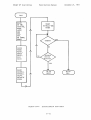
When power is applied to the main PCB, the Microprocessor Ini tializat:ion
sequence occurs automatically. The microprocessor then goes into the idle
state, in which it monitors the controller interface for a command. See
the INIT and IDLE flow charts for details.
The controller may then issue a Sequence Up command to the drive (the exact
manner in which this is done depends on the interface option present). The
microprocessor recognizes this command and starts the spindle motor.
When
the motor is running at the proper speed, the microprocessor reads the
sector length switches, and configures the drive to operate in terms of the
chosen sector length. Next it calls the RSTRGO subroutine, which moves
the heads
C"LtNDE£.. lle.O.
It then enables the drive ready status, resets the busy condition,
and returns to the idle state. See the CMDET, SEQUP, RSTRGO, and CMDEND
flow charts for details.
"'0
The drive is stopped by issuing a Sequence Down command.
This causes the
heads to return to the landing zone, and stops the spindle motor.
See the
SEQDWN and RSTR1 flow charts for details.
6.4
MOTOR CONTROL CIRCUITRY
The spindle motor is
DC motor. The speed
containing an optical
after October 1980 a
a brushless (electronic commutating) permanent magnet
of the motor is controlled by a closed-loop circui t
position encoder and a comparator. In drives shipped
crystal comparator is used.
The position of the rotor relative to the stator is encoded.
Two 90 0
shutters are attached to the spindle motor rotor and three phototransistors
(mounted 30 0 apart) are attached to the photocell circuit board. Each
phototransistor stops conducting when a shutter blocks its infrared LED
Ii gh t source.
With the exception of the phototransistors and the spindle motor itself,
all spindle rotation circuitry is located in the motor control assembly.
Figure 6.4-1 is a block diagram of the motor control circuitry. At the
point marked J2-4 the microprocessor sets the OFF signal true to inhibit
spindle rotation, or false to allow spindle rotation.
The microprocessor
monitors the speed of spindle rotation. If, during the power up sequence,
the motor does not reach its specified speed within one minute, or if,
during normal operation, the motor speed passes outside the specified speed
range, the microprocessor will set the Fault condition, restore the heads
to the landing zone, and inhibit the spindle rotation.
6-3
O,f
.
S3
U
J~
0fFl../1V
n
f
MODI
13
SELECT . . -
SWITCH
MODE
ONE
-I
SPD
,r
t>-=1
(j'l
RST
I
.r::.
RED
I'd
GREEN
H
~
~
.r::.
t:l
1-'-
rn
()
t:l
t1
1-'-
<:
(1)
rn
CONTROL
PULSE
I----!.ORMIR
.
IT1
tI
.-----------
i
I
h:j
OVERSHOOT
L1MIT.R
:
DRIVER
.AMP
I
II
I
14- lIT
COUNTER
~
ILACK
~
SINKS
~
""
FlU
PROM
S2
Sl
~
1
sou ICES
L_-
c-
1-'-
.'
SPD CONTROL I
.__
(1)
t-"
0.
i
I
m
(1)
I
----
t1
<:
1-'-
()
(1)
L-f
READYI
10% SPD
:s:
III
•
::s
J:,:
III
t-"
I
RUIT
I PULSE
~GENE
,
t--
Sl
RATOR
DYNAMIC
IRAKE
OVER I - RIDE
SINK
PO R ......,....DISA.U
~D~:;;'~
1~ ,L~;S
I
.1 =~:::I
ENAIU
Figure 6.4-1.
•
t:l
(1)
()
(1)
fr
T
,
I
(1)
Ii
N
~
~
Motor Controller
IDYNAMIC
IRAKE t-I- - - ,
,
~
1.0
00
PRIAM 14" Disc Drives
6.5
Field Service Manual
December 21, 1981
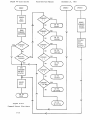
SEEK MODES
The servo system has two main modes of operation -- On Track mode (also
called Position mode) and Move mode.
Move mode becomes active when the drive is commanded to move the heads.
The microprocessor receives the new target cylinder address and the seek
command, determines the direction of travel and the number of tracks to be
crossed, and sets Move mode.
When the servo is in Move mode, a velocity profile (produced by a digitalto-analog converter) is compared (via a summing junction) with the output
of an electronic tachometer, which indicates the velocity of head motion.
The difference signal from the summing junction is fed to the servo power
amplifiers, which control the voice coil motion. The heads are driven
toward the new cylinder address.
The servo circuitry monitors the track
crossings and decreases the velocity of head motion as the selected
cylinder is approached.
When the heads are within 100 microinches of the new cylinder, the On Track
mode becomes active.
In the On Track mode, the heads are held precisely over the designated
track.
Any unintended head movement is detected by the electronic
tachometer and fed to the summing junction. This in turn causes the servo
power amplifiers to adjust the head position, so that the heads remain at
the desired location.
Servo safety circuits drive the heads to the landing zone upon detection of
a low power condition, or if both Move and On Track modes occur
simultaneously. The safety circuits also monitor the voice coil speed. If
the specified speed is exceeded, or if the continuous position information
is lost, an Overspeed signal is established and the servo power amplifi.ers
are disabled. Seek Fault is set if any of the above conditions develop.
For more details, refer to the SEEK, SEEKGO, LAND, HTRK, TRXING, SKDNE,
SKCMP, and SKERR flow charts.
6-5
PRIAM 14" Disc Drives
6.6
Field Service Manual
December 21, 1981
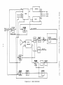
SERVO CIRCUITRY
Figure 6.6-1 is a block diagram of the head carriage servo circuitry.
The
signal from the servo head is amplified by a preamp located adjacent to the
head in the head disc assembly. On the main PCB it is further amplified by
an AGC amplifier. The output of this amplifier has the waveform shown as
ABCD in the figure, when the servo head is located midway between an odd
track and an even track, and the servo data pattern is all Os. A and Dare
the sync pulses occurring at the bit cell boundaries.
When a 1 is present
in the servo data stream, an addi tional "sync" pulse appears at the midcell position.
A sync detect circuit detects the sync pulses at the A and D positions, and
uses these pulses as input for the PLO (phase locked oscillator), which
generates a steady clock signal of approximately '6 MHz, which is phased
locked to the servo data.
The 1s and Os in the
shift register.
The
by a decoder, which
index pattern, and to
bit stream are identified and sent through as-bit
bit configuration in the shift register is monitored
recognizes the bit patterns that correspond to the
the three guardband patterns.
The pulses marked C and B are the pulses that occur at the 1/3 and 2/3
points in the bit cell. The pattern shown in Figure 6.6-1 corresponds to
an all Os servo data stream. The pulse at point 8 is the contribution from
the even servo track, while the pulse at point C comes from the odd track.
In the On Track mode, the Position Demodulator and On Track Compensator are
use to compare the Band C amplitudes, and 'to apply any discrepancies as an
error signal to the input of the voice coil power amplifier, in such a way
that the servo head remains midway between the two tracks.
In the Move mode, theB and C amplitudes are monitored, and the threshold
detector identifies the track crossings, outputting a TRK XING signal which
is used to update a cylinder address counter. The Velocity Tachometer,
Curve Generator, and Integrator Combiner together control the input to the
voice coil power amplifier, in order to control the head carriage velocity.
6-6
.B c
DVOLTs--t\A
1
=1=
FROM
""""NDI
"tI
lr
I
,....
D \
I
I
)
~ flVO
lilAD
OD D
SYNC
DETECT
I
I
I
PLO
.
J
WINDOW
FORMING t----,
PLO TTL.
GATE
.....,
I
----
I----,
-r'
r=
I
I
1116'
J
INDEX
GUARD
lAND
REGISTER
.......,
GENII ..
ATOR
WINDOW
5 .. lIT
SHifT
9
~
~NDEX
GIL 1
DECODE
GIL2
LATCHES
GIL 3
PlO 'MHZ
1
AGC
H
0
L
D
P D
E
M
0
D
U
o L
N A
T
0
R
o
S
I
T
I
~
tJ
.....
tJ
.TO
VFO
Ii
.....
~
CD
-..
M
P
L
'I
~
{fj
()
~
CARRIIR AMP
~
{Jl
TP
1I
ON
TIACK
'LO
LOCI!
POWIR
ON
RESET
CO",PI ..
NSATOI
I'1j
.....
CD
I--'
p,.
(f}
(1)
Ii
~
1-"
J'I
I
()
J5
r-·,
-..J
CD
• •
···•
...
•
u
•
>
I
I
0
u
I
I
•• •I
I
I
I
VEL
TP
VI
TP
1
III
:s:
DJ
::s
C
DJ
I--'
0
I
"'- ..J
tJ
CD
Figure 6.6-1.
()
(1)
Servo Circuitry
CURVI
fr
VELOCITY
CD
GINIRA101
I
L~ ~ -:::
•
-UK XING
Ii
TACHO"
METII
tv
~
CD
DAC 0-6
:
TO
PIOC
PRIAM 14" Disc Drives
6.7
Field Service Manual
December 21, 1981
DATA READ/WRITE FUNCTIONS
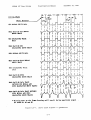
PRIAM disc drives use the MFM (modified frequency modulation) recording
method.
The MFM coding rules determine the relationship between the flux
transitions on the recording medium, the data being written, and the bit
cell boundaries. The following three rules must be observed:
If a 1 is written, there is a flux transition at the center of
the bit cell.
There is always a flux transition at the bit cell boundary
between consecutive Os.
There is never a flux transition at the boundary of a 0 and a 1.
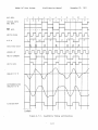
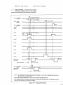
Figure 6.7-1 shows how the MFM encoding works out in practice. The bi t
cells are 120 nanoseconds long, which corresponds to a data read/write rate
of approximately 8 megabi ts per second. The MFM technique assures that
there will never be more than two bit-cell times between successive flux
transitions, and thus there will always be enough information to properly
reconstruct and synchronize the original NRZ data.
As shown in Figure 6.7-1, the write current to the selected data head
changes direction at each of the MFM transition points. The magnetization
on the disc is proportional to this current.
During read operations, the
signal from the read head is as shown on the ANALOG MFM line. The signal
is then differentiated, zero crossings are detected, and these (adjusted to
the nearby bi t-cell boundary or mid point) become the transi tions of the
LIMITED DATA line, which matches the original MFM data.
A data separator
later converts this back into NRZ data.
Figure 6.7-2 is a block diagram of the circuitry involved in the write
operation. The controller initiates a write operation by supplying the
disc drive with Head Select, Write Gate, Write Clock, and NRZ Write Data.
If the drive is selected and ready and if Write Protect is off, the write
operation will begin.
The write circuits will encode the NRZ data to MFM,
synchronize the data to the write clock, and record the data transitions on
the selected disc surface.
Safety circuits monitor the write operation.
If a fault is detected,
writing is inhibited, Fault is set, and Ready is inhibited.
6-8
BIT CELL
LOGICAL DATA
NRZ DATA
1
----
2
December 21, 1981
Field Service Manual
PRIAM 14" Disc Drives
3
0
0
0
T
T
l~T
4
1
6
5
1
0
7
..
~----
0
8
_.-.---.,- ..
9
----~--
1
1
10
11
-ll-'O--r-
NRZ DATA
HRITE CLOCK
M F H
2T
2T
DIGITTZED DATA
HINDOH 2F
hTRITE CURRENT
HRITE DATA
ANALOG M F H
DIFFERENTIATED
ANALOG H F H
LIHITED DATA
Figure 6.7-1.
Read/Write Timing and Encoding
6-9
2T
...
J6
,..
HD
-'"\.>C
···
:,
··
~
·
··
_.~
R/W
»
MATRIX
0
··
r'F
·
'"c
....
f"\
:
I
I
0
c
'"Z
I
2~
't
AND
DIFFEREM
TlATOR
-e
I
I
I
,
·
0
I
.RD CLK
HIGti
FILTER
PRE
AMP
f"\
I
HD
READ
0
· ··
· ··
··
··
I
I
.
---.
'"
,
....
l:-
»"'
r---'
~
...
....
g'"
n"'
...
J7
HD 1
~
...
____l
I
t'[j
v>
DATA
DELAY
AND
GAIN
UMITER
AMP
DATA
DETECTlON
..DATA
r--+ TO
DRIVER
SEPERATOR
1-"
o
Ii
1-'~
(1)
~,
"
en
+2F
~
-
f+.RD DATA _
~ TO I/O
BUS
...'"
t'Ij
"'
+DATA
I
I
I+READ
GATE
1-'(1)
~
OJ
'-- --~
0'
I
o
en
()
~
I
I
I/O
BUS
~
o
r:l
I
:
(f.l
(1)
Ii
~
~
1-'-
VFO
MUX
~
()
(1)
:s:
PJ
::s
~
PJ
~
... READ GATE
o(1)
()
(1)
+WRT
GATE
g.
(1)
Ii
....
....
\.0
tv
HEAD
SELECT
HIAD 51 LECT fROM RECVR
co
Figure 6.7-2.
Data Write Circuitry
PRIAM 14" Disc Drives
Field Service Manual
December 21, 1981
Figure 6.7-3 is a block diagram of the circuitry involved in the read
operation.
The controller initiates a read operation by supplying the disc
drive with Head Select and Read Gate.
The controller sets Read Gate true
in the gap area immediately preceding the desired data.
The gap area
serves to allow time for the data separation circuits to synchronize to the
recorded data.
During the read operation, voltage peaks of alternate polarities are
induced in the selected head. A voltage peak occurs at each detected data
transition. The following functions are performed by the read circuitry:
1.
Amplify, differentiate, and digitize the signal from the
read head.
2.
Verify the pulse width of the digital data and eliminate any
false zero crossings.
3.
Separate the data pulses from the clock pulses.
4.
Discard the detected clock pulses.
5.
Transform the data pulses to the NRZ format.
6.
Develop a Read Clock signal to identify the beginning of
each bit cell.
7.
Transmit the NRZ data and Read Clock to the controller.
A recoverable read error (soft error) resulting from a transient condition
can usually be corrected by re-reading the particular record involved.
An
error of this type is normally detected by the cyclic redundancy checking
(CRC) performed by the controller.
A non-recoverable error (hard error)
is one which persists after several
attempts to read the record. This may be a write error, in which case the
error is cleared by re-writing the record. A hard error may also be caused
by a disc surface defect, in which case the error may persist even after
the record has been re-written.
6-11
~IEMERGENaI
I
+ MULTI sn
"t1
~
JI
~
CONDITION
.
--..
DETECT
+ ACT
UNSAFE
~
~
t:l
1-'CIl
o
lao
J6/J7
r--,
• •
t:l
R/W :~
MA1RI" ..
Ii
1-'-
,0
<:
.
':
10
'I~m
"
_I '.1
i ~ HEAD SlL
:
CD
DRIVER
I
14
2
14
.0
-
, Iii'
C
-
+WRITE CLOCK
D~
WRITI
ENAlLE
WRITE
DRIVERS
HD SlL
IQ
Ul
READ/RE} CLOCK
I
I
'- __ J
Jl PRIAM
~.WRITI CLOC~
~
1-'-
CD
R
:
•'----'
I
p..
m
L.-Jf\----J
CURRE
0'1
I
CD
Ii
<:
IlIMITER
1-'-
~
l\)
I--'
,
.'
o
i
CD
r
CURR'NT
SINK
:s:
,---,
J9 SMD
III
~
~W.ITE $ATEI
CURRENT
L..I
I--'
t W R I T E pATA:
-WRITE GATE
MFM
SOURCI
~
III
!+.WRITI GAT E
.WRITE
DATAl
•
ENCODIR f;WRITI
DATA IRICllVfR
,.RECVD WRT CU
I
:
i
I
I
I
+WRITE fLOCI(
..
I
t
-WRITE ~lOCI<
C
I
t:l
CD
I
o
CD
:L __ JI
.WRITE
GATE
6-CD
Jl PRIAM
~
Ii
iT
l\)
HEAD
IIo-f SELECT
'--I DECODER
I
HEAD
SELECT FROM RECnV!R
(
\D
OJ
Figure 6.7-3.
Data Read Circuitry
PRIAM 14" Disc Drives
6.8
Field Service Manual
December 21, 1981
P:LO/VFO
Two of the circuits shown in Figure 6.7-3 are used to provide the proper
synchronization between the information recorded on the disc and the data
being transferred over the interface to the controller.
The PLO
proceeds at a uniform rate, while the VFD
is subject to variations
because of the analog nature of the write and read operations at the disc
and head level.
The VFO generates the clock signals to be sent to the controller. During
data read operations the raw data stream is used as a source of sync
signals.
The VFO adjusts its output clock frequency in such a manner that
the bit rate at the interface is equal to the average rate at which the bit
cell boundaries are detected in the raw data stream.
During procedures other than read operations, there is no data stream to
synchronize to. At these times the input to the VFO comes from the PLO,
which operates continuously from the servo data. Thus, for example, during
write operations, the PLO generates a surrogate clock to which the VFO
becomes a slave. The VFO output is used to generate the Read Clock signal
to the controller. The controller then uses this signal as a basis for the
Write Clock signal it returns with the data to be written.
6.9
MICROPROCESSOR FLOW CHARTS
This section contains the flow charts that gives details on the
microprocessor controlled sequences used in the disc drive.
When power is
initially applied to the main PCB, the INIT routine is automatically
executed.
The microprocessor then enters the IDLE state, where it wa.its
for a command, as shown in the IDLE flow chart.
If a command is received, the CMDET routine is executed. If the command is
not rejected (CMDREJ) the microprocessor executes the particular command
routine specified.
Power sequencing for the spindle motor is controlled by the SEQUP and
SEQDWN routines. Seek operations are controlled by the RESTOR and SEEK
routines, and their subroutines RSTR1, RSTRGO, SEEKGO, LAND, HTRK, TRXING.
Seek operations terminate with the SKDNE, SKCMP, or SKERR routines.
Commands in general terminate with the CMDEND or CMDREJ routines.
The Fault Reset command is executed by the FLTRST routine.
6-13
PRIAM 14" Disc Drives
Field Service Manual
INIT
RESET
START
ON TRK,
:3
40 MILLI--5EC
TACH POL,
TIMER
POSM,
+OFF,
ODD
FWD,
MOV,
WD TIMER,
READY
ISSUE
PWRON
RESET,
FAULT
RESET,
BUSY
RESET
NO
RESET
SKCMPLT,
SKFAULT,
CYL=O,
MOTOR AT
SPEED
Figure 6.9-1.
Initialization Flow Chart
6-14
December 21, 1981
PRIAM 14" Disc Drives
Field Service Manual
December 21, 1981
IDLE
RESET
WATCH DOG
TIMER
RESET
READY,
CYL=O,
SKCMPLT,
SKFLT
CALL
RSTRGO
SUBROUTINE
NO
SET
DRV FLT
SET
OFFTRK
NO
Figure 6.9-2.
Idle Flow Chart
6-15
RESET
OFFTRK
PRIAM 14" Disc Drives
Field Service Manual
December 21, 1981
CMDREJ
CMDET
ENABLE
W.D.
TIMER
CMDEND
RESET
COMMAND
REJECT
STATUS
READ
COMMAND
REGISTER
ENABLE
DRV
READY
STATUS
GO TO
RESTOR
NO
YES
SET
CONHAND
REJECT
STATUS
RESET
BUSY
NO
GO TO
IDLE
Figure 6.9-3.
Command Detect Flow Chart
6-16
SEQUP
TIME
SPINDLE
ROTATION
'INDEX
TO
INDEX'
I'Ij
1-'LQ
s::
Ii
CD
.
O'l
\0
I
~
READ
SECTOR
LENGTH
SWITCHES
..0
O'l
I
s::
CD
~
()
.....,J
CD
c::
RESET
READY,
SKCMPLT,
SKFLT,
CYL = 0,
LENGTH
~·10V ,
POSM,FWD
TURN
SPINDLE
MOTOR
ON
SET
COUNTER
o = ONE
SHOT 'TO
FIRE 36
BYTE CLK
AFTER
INDEX'
I'Ij
I-'
o
()
::r
OJ
Ii
It
START
1 MIN.
TIMER
SET
SEQUENCED
UP
J'
~
.....
o
1-'-
fJ)
()
o
<
CD
m
H
SET
MOTOR AT
FLAG
SPEED
I'Ij
1-'(1)
I-'
p,.
en
CD
Ii
RESET
READY
<
1-'()
CD
~
OJ
~
s::
OJ
CALL
I-'
TURN
SPINDLE
MOTOR
OFF
AGe SET
SUBROUTINE
o
(1)
()
(1)
g.
(1)
SET
DRVFLT
. INCH fire
L.
1
Ii
l\J
.....
NO
o
H
:t:oJ
Ii
1-'-
SET
COUNTERl
= RATE
GENE RAT 0
'RATE =
SECTOR
LENGTH
YES
~
::0
~
CALCULATE
SECTOR
LENGTH
'"0
~
SET
OUNTER 2
,,= RATE
TRACK
LENGTIt
MINUS
SECTOR
MINUS 3h
'BLOCK
SHORT
SECTOR'
en
CD
CALL
RSTRGO
SUBROUTINE
II
\0
00
PRIAM 14" Disc Drives
December 21, 1981
Field Service Manual
SEQDWN
TURN
SPINDLE
MOTOR
OFF
YES
NO
RESET
READY,
SKCMPLT,
SKFLT,
CYL = 0,
MOTOR AT
SPEEDFLAG
GO TO
CMDEND
SET
ACCESS
TYPE =
LAND
HEADS
CALL
RSTRI
SUBROUTINE
Figure 6.9-5.
Sequence Down Flow Chart
6-18
RSTRGO
"t1
~
~
-"
~
SET
ACCESS
TYPE
RESTORE
t:l
~.
en
n
YES
GO TO
CMDREJ
<:
(1)
RESET
MOVE,
SEQ UP,
MOTOR AT
SPD
\-/. D.
TIMER
1.0
~.
(J)
START
O'l
I
t:l
Ii
RESET
READY
SKCMPLT
SKFLT
CYL=O
....,
....
i
OJ
CIl
(1)
Ii
0\
CALL
RSTRGO
SUBROUTINE
.
"m
CI
G1
l'1'
o
t1
(D
....,
RESET
DRIVE
FAULT
~
~
()
::r
PIl
<:
~.
n
RESET
TACHPOL,
ONTRK,
ODD,
POSM
(D
.
"'%j
~.
(1)
I-'
~t1
\D
I
0\
RM1P
DOWN
VRLOCITY
TO
.075 IPS
SET
DIR-REV
MOVE
(1)
3:
III
NO
RAHP
DOWN
VELOCITY
TO
0.75 IPS
SET
DIR-F\ID
p
III
I-'
DELAY
4
MILLISECS
t:l
(1)
n
(1)
6-
SET
VEL =
2.0 IPS
(1)
Ii
N
GO TO
HTRK
~
::s
--'
--'
1.0
co
\.
~ID~~D
)
PRIAM 14" Disc Drives
Field Service Manual
December 21, 1981
CALCULATE
DIFFERENCE
BETWEEN
CURRENT
CYLINDER
AND TARGET
CYLINDER
SEEKGO
SEEK
READ]
TARGET
ADDRESS
GO TO
CMDREJ
YES
GO TO
CMDREJ
CALL
SEEKGO
NO
START
\oJ. D.
TIHER
GO TO
SKCMP
NO
CALCULATE
TACH
POLARITY
(5)
RESET
DRIVE
FAULT
GO TO
C~IDEND
Figure 6.9-7.
RESET
READY
SKCMPLT
SKFLT
CYL=O
J
SET
ACCESS
TYPE =
SEEK
Seek Operation Flow Chart
6-20
SET
FWD OR
REV
AND
TACHPOL
RESET
POSM,
SET
MOVE
PRIAM 14" Disc Drives
December 21, 1981
Field Service Manual
TRXING
USE
DIFF CNT
TO FETCH
VELOCITY
FROM
TABLE
SET
VELOCI
• 25 IP
SET
IFF CNTR
DIFF -1
NO
YES
START
DIFF CNT
OVTPl'T
VELOCITY
BEGIr-\
CrRVE
FILL TILl
!\[XT
TRACK
XI~G
YES
GO TO
LAND
Figure 6.9-8.
Track Crossing Flow Chart
6-21
PRIAM 14" Disc Drives
Field Service Manual
December 21, 1981
HTRK
LAND
START 3
MILLI SEC
TIMER
SET
VEL =
.075 IPS
RESET
MOVE
GO TO
SKDNE
rAT-THIS -
I POINT THE
I SERVO HAS
i
I MOVED OFF
I OF TARGET
I
I
I
SET
POSM
I TRACK - 1
I APPROACH-II
lING THE
I TARGET
LT~CK __
I
J
GO TO
SKERR
YES
SET
ONTRK
Figure 6.9-9.
Land and On Track Flow Chart
6-22
PRIAM 14" Disc Drives
Field Service Manual
December 21, 1981
SKERR
SKCMP
SKDNE
SET
SKFLT
SET
CAR = 0
SET
CAR=TAR
GO TO
RSTRGO
SET
ACCESS
TYPE =
LAND
SET
OR
RESET
CYL=O
CALL
RSTRI
SUBROUTINE
NO
SET
SKCMPLT
SET
READY
SUBROUTINE
RETURN
Figure 6.9-10.
Seek End Flow Chart
6-23
PRIAM 14" Disc Drives
Field Service Manual
FLTRST
RESET
SKFLT,
DRIVE
FLT
NO
SET
READY
GO TO
CMDEND
Figure 6.9-11.
Fault Reset Flow Chart
6-24
December 21, 1981
PRIAM 14" Disc Drives
SECTION 7 -
Field Service Manual
December 21, '1981
TROUBLESHOOTING PROCEDURES
The overall purpose of field service for PRIAM disc drives is to rest.ore
system operation by the quickest and most economical means possible.
This
usually involves replacement of a faulty or suspected assembly with an
operational spare. The assembly in question may then be returned to a
PRIAM repair depot for component level diagnosis and repair.
Requests for maintenance assistance may be directed to PRIAM's Customer
Service Department. PRIAM offers the following services:
7. 1
1.
Telephone Assistance:
Service representatives are available
(during PRIAM's normal working hours) to assist customers
with maintenance, interfacing, and spare parts inquiries.
2.
On-site Assistance:
PRIAM can provide a factory trained
technician to assist the customer's system technician in the
testing and repair of PRIAM products.
3.
Factory Repair: PRIAM maintains a repair facility at its
factory for the convenience of its customers. An entire disc
drive, or any repairable assembly, may be returned to PRIAM
for repair.
Contact PRIAM Customer Service for a return
authorization number prior to shipping any drive or assembly
to PRIAM.
FIELD ADJUSTMENTS AND PREVENTIVE MAINTENANCE
PRIAM 14-inch disc drives require no field adjustments and no preventive
maintenance.
7.2
GENERAL INSPECTION
The following checklist may be used as a preliminary procedure to be
performed whenever a disc drive is suspected of being faulty:
1.
Check that the spindle lock and the head carriage lock are
both in the UNLOCK position.
2.
Check for proper DC voltages within the disc drive,
described in the OPERATING PROCEDURES section.
3.
Check the fuse in the power supply.
4.
Check the fuse in the motor control assembly.
5.
Check that the device address, write protect, and sector size
switches are correctly set, according to the information
given in the INSTALLATION section.
6.
Check for component discoloration, and for loose or faulty
connections.
7.
Check and recheck all cable and controller connectors.
7-1
as
PRIAM 14" Disc Drives
Field Service Manual
December 21, 1981
If all of the above items seem to be in order, a kind of high-level trouble
shooting can be performed, simply by replacing each of the major assemblies
one-by-one until the problem disappears. This obviously works best on
problems that are stable, as opposed to intermittent.
Replacement of the
main PCB will confirm the operation of approximately 85% of the electronic
circuits in the entire disc drive.
A more symptom-specific approach to troubleshooting is described below in
the SYMPTOMS AND CAUSES section.
7.3
STATUS AND ERROR CODES
The disc drive is capable of providing quite a bit of information
concerning its internal conditions, by means of status indications on the
user interface. The exact information available, and the signal lines
involved depend on the specific interface used.
This is discussed further
in the sections describing each individual interface.
See also the section
on SEEK ERRORS AND FAULT CONDITIONS (below).
7.4
SYMPTOMS AND CAUSES
The functions performed by the disc drive fall into the following five
categories:
1.
Spindle Rotation
2.
Command/Status Transfer
3.
Head Positioning/Servo
4.
Data Write Operations
5.
Data Read Operations
In the pages immediately following, symptoms are listed from each of these
categories, along with possible causes and the corresponding suggested
courses of action.
7-2
PRIAM 14 11 Disc Drives
Field Service Manual
December 21, 1981
SPINDLE ROTATION
Symptom
Possible Cause
Suggested Action
Rotation does
not start.
Spindle locked.
Place in UNLOCK position.
Incorrect or zero
voltage at main PCB
connector J3.
Check power supply.
+OFF signal (J4-4)
is +5 VDC (should
be 0 volts for
rotation).
Check microprocessor reset
signal on main PCB.
Check power-on reset (POR).
Check power reset (PRST).
All these should be false.
Defective motor
control assembly.
Check fuse in motor control
assembly. Check LED voltage
at J1-5 for the following:
+12 VDC on the 3350
+4 VDC on the 6650
VDC on the 15450
Spindle rotates,
but stops after
about one minute.
Defective photocell
assembly.
Check for open LED, defective
connector or phototransistor.
Defective spindle
motor.
Manually rotate spindle in
clockwise (viewed from
bottom) direction only.
If motor is binding, replace
entire disc drive. Depot
repair is required.
Head carriage
locked.
Place in UNLOCK position.
Defective motor
control assembly.
Replace motor control
assembly.
Defective photocell
assembly.
Replace photocell assembly.
Speed control not
being sensed by
microprocessor.
Replace main PCB.
Spindle motor has
excessive drag.
Replace entire disc drive
(depot repair required).
7-3
PRIAM 14" Disc Drives
Field Service Manual
December 21, 1981
SPINDLE ROTATION (continued)
Symptom
Possible Cause
Suggested Action
Spindle rotates,
but drive does
not come Ready,
or Ready comes
and goes.
Fault condition.
Check Fault status.
Intermittent power
supply failure.
Replace power supply.
Defective main PCB.
Replace main PCB.
Defective motor
control assembly.
Replace motor control
assembly.
Defective head disc
assembly.
Replace entire disc drive
(depot repair required).
Comments: Upon completion of power on reset (POR) the microprocessor disables
the +OFF signal to the spindle motor.
With +OFF at 0 volts the
spindle motor should rotate at its specified speed (3100 RPM).
The microprocessor examines Index Marks to determine spindle speed.
If the specified spindle speed is not reached within two minutes,
the +OFF signal is enabled and spindle rotation is stopped.
Power to the disc drive must be cycled (off and then on) to allow
the microprocessor to disable the +OFF signal.
The following diagram shows the connections among the main PCB,
motor control assembly, spindle motor, and photocell assembly.
Mal.n
. PCB
J4
Ground
+24 VDC
Not Used
+OFF
+5 VDC
Ground
Mo t or Con t ro 1 Assem bl.y
Pin
J2 Pin
1
2
3
4
5
1
2
3
4
5
6
6
8 pl.n
. dl e Motor
J1 Pin
8
7
6
5
4
3
2
1
Black
Green
Red
+LED
S1
S2
83
Ground
Photocell
Assembly
1
I
7-4
PRIAM 14" Disc Drives
Field Service Manual
December 21, 1981
COMMAND/STATUS TRANSFER
Symptom
Possible Cause
Suggested Action
Incorrect state
on Unit Selected.
Wrong setting on
device address
switch.
Refer to Section 2.4 for
correct switch settings.
Pick and Hold false or
Open Cable Detect true
(SMD interface only).
Check controller, cable,
and connectors.
Unit Select Tag or
Unit Address missing
or mistimed (SMD
interface only).
Check controller, cable,
and connectors.
Drive not Ready.
See SPINDLE ROTATION (above).
Fault condition.
See FAULT CONDITIONS
section (below).
Defective main PCB.
Replace main PCB.
Selected drive
does not accept
commands.
Tag and bus data
malfunction (SMb
interface only).
Check controller, cable,
and connectors.
Selected drive
issues Fault.
Fault condition.
See FAULT CONDITIONS
section (below).
Selected drive
issues Seek
Error.
Defective servo
operation.
See HEAD POSITIONING/SERVO
(below) •
Selected drive
fails to issue
Index.
Defective main PCB.
Replace main PCB.
Selected drive
does not~ issue
status.
Comments: During servo and data write operations, most circuit functions
are monitored by the microprocessor.
If Ready is true and Fault
is false, i t is likely that the spindle speed, servo, and data
write circuitry are all funtioning in a normal manner.
7-5
PRIAM 14" Disc Drives
Field Service Manual
December 21, 1981
HEAD POSITIONING/SERVO
symptom
Possible Cause
Suggested Action
Drive fails to
move to new
address.
Command transfer
circuitry defect.
See COMMAND/STATUS TRANSFER
(above) •
Continuous
Seek Error
condition.
Defective circuitry.
Defective servo circuitry on
main PCB. If fault persists
with operational spare, and
the fault is not in the spindle
speed circuitry, replace the
entire disc drive.
Faulty connection to
servo read head.
Check connector J6.
Faulty connection to
voice coil actuator.
Check connector J5.
Incorrect power
voltage.
Check connector J3. Refer to
Section 3 for correct voltages.
Head carriage
locked.
Place in UNLOCK position.
Inadequate signal
from controller.
Check controller, cable,
and connectors.
Defective circuitry
or servo system.
Defective circuitry on main
PCB. If the symptom persists
with operational spare, and
the fault is not in the
controller or cable, replace
the entire disc drive.
Drive seeks to
wrong cylinder.
Comments: Note that the seek operation may be normal, while the circuitry
that checks for correct seek location may be defective.
A large number of symptoms may be associated with malfunctions of
the servo circuitry.
If servo malfunction is suspected, the
recommended procedure is to replace the main PCB. If the head
disc assembly is defective, it is highly likely that non-servo
related faults (e.g., data errors, failure to come Ready, Fault
status true) will also be in evidence.
7-6
PRIAM 14" Disc Drives
December 21, '1981
Field Service Manual
DATA WRITE OPERATIONS
Symptom
Possible Cause
Suggested Action
Fault is set
with each attempt
to write data.
Incorrect switch
setting or circuit
defect.
Verify whether multiple heads
have been selected. If this
is the case, the following test:
point will be high:
TP
TP
TP
on the 3350
on the 6650
on the 15450
Check for the Act Unsafe
condition. Act unsafe will
be high if there are write
transitions with Write Gate
false, or no write transitions
with Write Gate true.
See the section on SEEK ERRORS
AND FAULT CONDITIONS for o·ther
possibilities and corresponding
suggested actions.
Data is written
incorrectly and
Fault does not
set.
Difficulty in data
read operation.
See DATA READ OPERATIONS
(below).
DATA READ OPERATIONS
Symptom
Possible Cause
Suggested Action
Drive fails to
read, but will
write without
a Fault.
Defect in read
circuitry.
Check all cable connections.
Replace terminator.
Replace main PCB.
Drive reads data
Difficulty in data
write operation.
fields and header
fields correctly,
but will not read
newly written data.
See DATA WRITE OPERATIONS
(above).
If Fault is set
during write operation, see
the section on SEEK ERRORS
AND FAULT CONDITIONS.
Comments: If read errors persist after replacement of the terminator and
the main PCB, and if the cable connections are correct, it is
possible that the format being used is erroneous.
If the format is correct, replacement of the entire disc drive is
recommended.
7-7
TEST POINT CHART
TEST
POINT
TYPE
LOCK
14"
(200149-SMD)
ORIGIN
DESCRIPTION·
LOC
GND
Read Amp
+Analog MFM Data (To TP5)
Ground "c" (with TPl & TP5)
Digitized Read Data
READ GATE
-Analog MFM Data (with TP1)
VCO Feedback
+SYNC
ENABLE
DATA (Data Sep)
NRZ Read Data
+Phase Error (VFO)(with TPI4)
DATA (Read MUX Output) (PLO)
Data Window
-Phase Error (VFO) (with TP11)
VFO Control Voltage
Ground "c" (VFO Ref)
PLO Correction Voltage
+WRT CLK (MFM Write Data)
-Phase Error (PLO with TP26)
2E3
2F3
2E9
2C7
2F3
2B6
2C7
2D6
3F6
3F4
2C5
2C6
3F6
2C5
2B4
2C4
3D2
3E2
3D4
C
OpAmp Digital R/W Drvr
GROUND
+ACT UNSAFE
Ground "B"
ID2
3Cl
B
OpAmp Digital Head Sel
TTL_D!gital
+MULTI SEL (Head Bias)
+Phase Error (PLO with TP19)
lC2
3D4
B
B
TTL Digital
TTL Digital
OpAmp Analog
OpAmp Digital
OpAmp Analog
OpAmp Analog
OpAmp Analog
TTL Dig
OpAmp Analog
PLO Error
PLO Cntr
Servo Amp
Servo Car
Servo Pos
Servo Pos
Servo Vel
uP Cntl
Servo Pos
+MSB - 2 (To PLO Error Det)
+MSB
AGC'D Servo Data (Carrier)
Sync Detect
Servo Position Peak B
Servo Position Peak A
TRKXING Filler
+MOVE (High During Seek)
Position Demod
3D5
3C7
5F3
B
4D5
4D5
5C7
5B6
4D4
TSTR Alog
GROUND
ECL Digital
ECL Digital
TSTR Alog
TPI
TP2
TP3
TP4
TP5
TP6
TP7
TP8
TP9
TPI0
TPII
TP12
TP13
TP14
TP15
TP16
TP17
TP18
TP19
TP20
TP21
TP22
TP23
TP24
TP25
TP26
TP27
TP28
TP29
TP30
TP31
TP32
TP33
TP34
TP35
TP36
TP37
TP38
TP39
TP40
TP41
TP42
TP43
TP44
TP45
TP46
TP47
TP48
TP49
TTL Dig
OpAmp Analog
D/A Analog
GROUND
Servo HTK
POS
uP D/A
H-SW Servo
+Inihibit Differentiators
Position Signal
+CURVE D/A (Target Velocity)
Ground "E" (H-SW)
5B6
4D3
6E3
5Dl
OpAmp
OpAmp
OpArnp
OpAmp
OpAmp
OpAmp
H-Sw Servo
H-SW
Velocity
POS
POS
H-SW
IR (Voice Coil Current)
Velocity (from Coil Current)
Servo Error (To H-SW Error)
Filtered Position
TACH Differentiator Out (DXA)
Velocity In Tach
5C2
4A4
5E6
4D3
4B3
4B5
TP501
TP502
TPS03
TTL Dig
TTL Dig
TTL Dig
INTF
INTF
Servo SD
SECTOR MARK
READY· BUSY (to D Rdy)
INDEX
7-8
8D4
8C3
4F3
ECL Digital
ECL Digital
ECL Digital
ECL Digital
ECL Digital
ECL Digital
ECL Digital
ECL Digital
OpAmp Analog
GROUND
ECL Digital
TTL Digital
Alog
Analog
Analog
Analog
A/D
Analog
Read Amp
I/O
Read Amp
uP Cntl
uP Cntl
Read DIy
Data Sep
VFO Cntl
MUX
VFO
VFO Cntl
VFO Cntl
MFM Encdr
C
C
C
C
C
C
C
C
C
C
WAVE
FORl-1
30
C
C
33
B
4
B
D
D
D
D
D
D
D
3
1
2
5
5
10-15,22
10-16,20
10-16,20
16
E
D
E
D
17,18
24
23,26
10-16,20
19
D
35,36
B
34
TEST POINT CHART 14 INCH DISK
(200173-PRIAM)
WAVE
FORM
TEST
POINT
TYPE
LOCK
ORIGIN
DESCRIPTION
LOC
GND
TPI
TP2
TP3
TP4
TPS
Tstr Analog
GROUND
ECL Digital
ECL Digital
Tstr Analog
Rd Preamp
Rd Preamp
Rd Limit
Rcvr
Rd Preamp
+Analog MFM Data (with TPS)
Ground "c" Read Preamp
Digitized Read Data (MFM)
+Read Gate (to Read Mux)
-Analog MFM Data with TP1)
2E3
2F3
2E8
C
2F3
TP7
ECL Digital
Wr Clk
+Sync (Delay 9 bytes)
2C7
TP9
TPI0
ECL Digital
ECL Digital
Data Sep
Data Sep
Data (into Data Sep)
NIlZ Read Data
3E6
3F3
C
C
TPl3
ECL Digital
VFO
Data Window (Separator)
3F6
C
TPlS
TP16
TPl7
TPl8
OpAMP Alog
GROUND
OpAmp Alog
ECL Digital
VFO
VFO
PLO
2B3
2C4
C
33
3E4
B
C
4
MFM
VFO Control Voltage
Ground "c" for TP1S
PLO Correction Voltage
+WRT CLK (MFM Write Data)
TP20
TP21
TP22
GROUND
OpAmp Digit
GROUND
R/W
R/W Drvr
PLO
Ground "A" R/W Heads
+Act Unsafe (not latched!)
Ground "B" (for TP17)
lES
ID2
3C2
B
TP2S
OpAmp Digit
R/W Heads
+MultiSel (bias to 2 heads)
lC2
B
TP28
TP29
TP30
TTL Dig
TTL Digital
OpAmp Alog
uP Expdr
PLO Cntr
Servo Amp
+FWD (
+MSB (PLO divided by 32)
AGC'D Servo Data (Carrier)
3B6
SF3
D
D
TP3S
TP36
TTL Digital
OpAmp Alog
uP Expndr
Servo Pos
+Move (high during seek)
Position Demod (Peak Det)
SB6
4D4
D 10--15,22
D 10-16,20
TP40
TP41
TP42
OpAmp Alog
OpAmp Alog
GROUND
Servo Pos
uP D/A
Servo H-sw
Position Signal (
+Curve D/A (Target Velocity)
Ground "E" (H-Switch)
4D3
6E3
SD1
D 10-16,20
D
TP44
TP4S
TP46
TP47
TP48
OpAmp
OPamp
OpAmp
OpAmp
oPAmp
Servo
Servo
Servo
Servo
Servo
SC2
4A5
SE6
4D2
4B2
E
17,18
24
D
23,26
E
D 10-16,20
19
D
TP50
TPSl
TTL Digital
uP Expndr
-PSYC (to PLO Corrector
3A5
B
TP50l
TP502
TTL Digital
TTL Digital
uP Cntr
Status
Sector Mark
Ready & not Busy (to DRDY)
8D4
H
Be3
Alog
Alog
Alog
Alog
Alog
Ecdr
H-Sw Motor Current (to Voice Coil)
H-Sw Velocity (from Coil Current)
H-SW Servo Error (to H-Switch)
Pos
Filtered Position
Pos
Tach Differentiator Out
7-9
C
C
C
30
3
1
37
35,36
TEST POINT CHART
TEST
PIN
TYPE
LOGIC
ORIGIN
14 INCH ANALOG BOARD
(200214)
DESCRIPTION
LOC
GND
SDI
7Bl
D
D
WAVE
FORM
(CHIP SOCKET LOCATION IS 16F ON ANALOG PCB)
Pin
Pin
Pin
Pin
Pin
Pin
Pin
Pin
Pin
Pin
Pin
Pin
Pin
Pin
Pin
Pin
1
2
3
4
5
6
7
8
9
10
11
12
13
14
15
16
OpAmp Alog
OpAmp Alog
TTL Dig
OpAmp Alog
Ref
Ref
Servo S/H
D/A Curve
uProc
OnTrack
Servo
Servo
POSN (Filtered Position)
D/A (Analog Target Velocity)
-POSN (Position Mode)
COMP
BODE 1 (Ref 24K)
BODE 2 (Ref lK)
OpAmp Alog
GROUND
OpAmp Alog
OpArnp Alog
TTL Dig
OpAmp Alog
Analog
OpAmp
OpAmp Alog
Servo S/H
POS (Position Demod)
GROUND "D"
CRV (Sw Target Vel)
DXB (Differentiated Position)
-FWD (Same as TP22)
GC (Analog AGC from D/A)
IR (Voice Coil Current)
D/A Curve
Servo Pos
uProc
AGCC uP
H-Switch
Servo Pos VD
Voice Coil VEL (Integral of IR)
TEST POINT CHART
TPI
TP2
TTL Dig
TTL DIG
Alog Bd
Decoder
TEST POINT CHART
TPI
TP2
TP3
TTL Dig
TTL Dig
TTL Dig
Alog Bd
Decoder
Busy FF
14 INCH SPLIT SMD
INDEX
SECTOR MARK
BUSY FF
7-10
BDI
7Bl
SDI
SDI
D
D
D
SE1
SCI
7A1
6Dl
D
BEl
7F1
7B1
6E1
6Dl
4D3
4E3
PRI~1
D
D
D
D
D
D
10-16,20
17,18
24
(200264)
INDEX
SECTOR MARK
14 INCH SPLIT
10-16,20
16
34
35,36
(200209)
3D3
3E4
1A7
34
35,36
TEST POINT CHART
TEST
POINT
SIGNAL
TYPE
TPl
TP2
TP3
TP4
TP5
TP6
TP7
TP8
TP9
TPlO
TPll
TP12
TP13
TPl4
TPl5
TPl6
TPl7
TPl8
TPl9
TP20
TP2l
TP22
TP23
TP24
TP25
TP26
TP27
TP28
TP29
TP30
TP3l
TP32
TP33
TP34
TP35
TP36
TP37
Tstr Analog
GROUND
Tstr Analog
ECL Dig
ECL Dig
ECL Dig
ECL Dig
ECL Dig
ECL Dig
ECL Dig
ECL Dig
ECL Dig
GROUND
Tstr Analog
OpAmp Alog
ECL Dig
GROUND
OpAmp Dig
OpAmp Dig
TTL Dig
OpAmp Analog
14" ANALOG
15450
(200214)
ORIGIN
DESCRIPTION
LOe
GND
Read Amp
2F3
2F3
2E3
3F8
3B8
4F3
4E5
3e8
3D6
3B7
3e5
4F5
3C4
3e3
3F4
e
VFO Cntl
VFO Cntl
+Analog Read Data (with TP3)
Ground "c" (Read Amp Ref)
-Analog Read Data (with TPl)
Digitized Read Data (MFM)
+Sync
NRZ Read Data (To XMTRS)
Data (MFM Data to Separator)
Read Gate A (To MUX)
Data (Data or PLO to VFO)
ENABLE (Sync Read Gate)
VCO Feedback (VFO)
Data Window
Ground "e" (For VFO Ref)
VFO Error (R40 to Gnd "e")
VFO Correction Voltage
Head Sel
Head l~r
Servo Pos
PLO Cntl
Ground "A"
+Multi Sel
+Act Unsafe
-TRKXING
PLO Correction Voltage
2el
2Bl
2el
6E2
6B5
D
D
OpAmp Analog
OpAmp Dig
Servo Amp
Servo Amp
Carrier
SD (Sync Detect)
5E5
5Fl
D
TTL Dig
TTL Dig
PLO Cntl
Servo Pos
+PLO Error (to PLO,TP2l)
-FIRK (±lOOu" Off track)
6A7
6F2
D
TTL Dig
OpAmp Alog
TTL Dig
Servo Pos
-HTRK (±500u" Off track)
Servo Data
Servo Data
PLO Cntl
Servo Data
FWD ODD (Clocked by :Move)
GBl (Guardband near Data)
GB2 (Head Landing Zone)
-PLO Error (to PLO,TP2l)
INDEX (unshaped)
6E2
6E2
6E5
6e6
6B6
6A7
6e6
TTL Dig
Read
Read
I/O
Data
Read
Amp
Amp
Sep
Amp
RCVR
Read Amp
Clocks
VFO
VFO Div
7-11
WAVE
'FORN
e
c
30
c
c
c
C
C
c
e
e
c
33
F
F
D
F
D
D
D
F
F
F
F
4
1
2
PRIAM 14" Disc Drives
7.5
Field Service Manual
December 21, 1981
SEEK ERRORS AND FAULT CONDITIONS
Seek errors result when a head does not lock on the target track. Whenever
a seek error occurs, the drive's track counter is reset to zero. This is
done automatically by restoring the head to cylinder zero. The fault must
be reset, and a new seek command may then be issued.
The Seek Error indication will be set true whenever the microprocessor
detects any of the following conditions:
1.
Seek Incomplete (track following servo unable to lock onto
track within the prescribed time).
2.
Restore or Rezero not completed within the prescribed time.
3.
Invalid seek address detected (SMD, ANSI and B4 inerfaces only).
4.
Guardband Error (servo head has entered the guardband area).
When the microprocessor detects one of these conditions, it issues an
internal Restore or Rezero command, which returns the head to cylinder 000
and sets a Seek Error Latch. The Seek Error Latch must be cleared by a
Fault Reset, Restore or Rezero command issued to the drive by the user.
The exact manner in which the Seek Error indication appears on the user
interface depends on which interface option is present. See the individual
interface description sections for ,details.
Fa ul t status is set, Ready is disabled, and wr i ting of data is inhJ_bi ted
whenever the safety circuitry on the main PCB detects a Fault conciton.
The following list discusses the possible origins of such a conditon, and
suggests what remedial actions could be taken in each case:
1.
Write Gate true with Write Protect switch ON (or Write Enable
switch OFF).
Check switch for correct setting.
2.
Act Unsafe (Write gate without Write Current or Write Current
without Write Gate).
If the fault is isolated to an individual head, then (with
power off) check the head assembly for continuity.
If the
head assembly is faulty, return the entire disc drive to a
repair depot.
If the fault occurs on all heads, replace the main PCB.
3.
Multiple heads selected (only one data head should be selected at
a given time).
Check the center tap of each data head.
should have +7 VDC.
Only one data head
If more than one data head center tap is at +7 VDC, replace
the main PCB.
7-12
PRIAM 14" Disc Drives
4.
Field Service Manual
December 21, 1981
Write Gate and Read Gate both true at the same time.
Check the controller for proper operation and the interface
cable for the proper connections.
If the problem persists, replace the main PCB.
5.
Write Gate true, but heads not precisely located over the
designated cylinder.
Replace the main PCB.
If the problem persists, replace the entire disc drive.
6.
No seek request, but head movement is detected.
Replace the main PCB.
If the problem persists, replace the entire disc drive.
7.
The PLO signal is not synchronized.
Replace the main PCB.
If the problem persists, replace the entire disc drive.
8.
Spindle rotation is outside of specification.
Check the motor control assembly for a defective component.
Check the photocell assembly for a defective connection,
LED, or phototransistor.
Check the power supply for a defective connection,
voltage level, or component.
DC
If the fault can not be corrected by replacing the motor
control assembly, photocell assembly, and power supply,
then replace the entire disc drive.
9.
More than one control tag is active (SMD and B4 interfaces only).
Check controller, cable, and procedures.
If the problem persists, replace the main PCB.
If any of conditions 6,7, or 8 (above) are detected, the microprocessor
will attempt a restore to cylinder 000.
Any of the following measures will reset Fault status:
1.
Power On Reset -- remove and reapply DC power.
2.
Fault Clear -- Tag 3 and Bit 4 on interface "A" or BUS cable (SMD
and B4 interfaces).
3.
Fault Reset command (PRIAM and ANSI interfaces).
3.
Ground potential at J8-2.
7-'3
PRIAM 14" Disc Drives
SECTION 8 -
Field Service Manual
December 21, 1981
ASSEMBLY REPLACEMENT PROCEDURES
All of the replaceable assemblies in a PRIAM disc drive may be removed and
replaced using standard hand tools.
It is highly recommended that
maintenance personnel use the assembly replacement approach to field
service, rather than attempting component level repair.
8.1
PRECAUTIONS
1.
Always make sure that the head lock and spindle lock levers are
both in the LOCK position before the drive is moved in any way.
2.
Always make sure that the power is off when removing or
reinserting any printed circuit boards or connectors.
3.
Use proper size screwdrivers, wrenches, and other tools. Keep
track of the screws and other parts you remove, and use the same
hardware when reinstalling each assembly.
4.
Use properly calibrated test equipment.
5.
Keep accurate records of all observations made during servicing.
Before attempting to remove any assemblies, make sure that both the spindle
lock and head lock levers are in the LOCK position.
The spindle lock
engages the fan on the spindle motor shaft. To lock it, rotate the spindle
clockwise (as viewed from the bottom) until the teeth of the lock can fit
onto the blades of the fan. The head lock is a wire lever, which should be
pulled out, then turned to the LOCK position. If it does not turn easily,
gently lift the far end of the drive so that the head carriage will return
to the fully retracted position. Then turn the lever to LOCK.
8.2
HEAD DISC ASSEMBLY
The head disc assembly (HDA) is a sealed contamination-resistant enclosure
containing all moving parts in the disc drive. It should not be opened for
any reason.
If the HDA is defective, the entire disc drive should be
returned to a qualified repair depot. Do not remove the HDA from the frame
assembly.
8-1
PRIAM 14" Disc Drives
8.3
Field Service Manual
December 21, 1981
PHOTOCELL ASSEMBLY
The photocell assembly is mounted on the bottom of the motor spindle.
To
remove the photocell assembly, first unplug the connector at the motor
control assembly.
Then remove the two mounting screws, which can be
accessed through the holes provided in the perforated cover over the bottom
of the spindle.
When you install the replacement board, be sure to locate
the LEDs in exactly the same location relative to ·the shutters.
8.4
MOTOR CONTROL ASSEMBLY
The motor control assembly is mounted on the bottom of the frame.
To
remove the motor control assembly, first unplug the two connectors.
'I'hen
remove t:he three mounting bolts and release the two plastic retainers.
8.5
MAIN PCB
The main PCB is mounted on the top of the frame.
To remove it, first
unplug all the connectors, carefully noting their positions and
orientat.ions for later replacement. Then remove the eight mounting screws.
Extreme care should be taken in removing the IC connectors, especially
those going to the head disc assembly. Gently pry the connectors off,
using a suitable size slender screwdriver. If the connectors to the HDA
are broken, it will be necessary to replace the entire disc drive.
8.6
POWER SUPPLY
The power supply may be mounted separately from the disc drive, or it may
be mounted on the bottom of the frame. If it is mounted separately, simply
unplug the power connector.
If it is mounted in the frame, unplug the
connector and then remove the power supply mounting screws.
8-2
PRIAM 14" Disc Drives
Field Service Manual
December 21, 1981
SECTION 9 - SPARE PARTS LIST
Replaceable assembly part numbers are given below.
Additonal part number
information (and/or a bill of material listing for customers establishing
depot repair) is available from PRIAM Customer Service.
Head Disc Assembly (3350)
Head Disc Assembly (6650)
Head Disc Assembly (15450)
330330
330410
331003
Photocell Assembly
200053
Motor Control Assembly
200083
Main
Main
Main
Main
200113 (OLD}
200088 [OLD)
PCB
PCB
PCB
PCB
(PRIAM Interface)
(SMD Interface)
(ANSI Interface)
(Basic Four Interface)
200098
Frame Assembly
330397
15450 Split PRIAM Interface
15450 Analog PCB
15450 Split SMD Interface
200208
200213
200263
Power Supply (3350)
Power Supply (6650)
Power Supply (15450)
330358
330352
Power Cord
101116
Mounting Slides (3350)
Mounting Slides (6650)
Mounting Slides (15450)
330143
330183
Terminator
Terminator
Terminator
Terminator
200133
200128
(PRIAM Interface)
(SMD Interface)
(ANSI Interface)
(Basic Four Interface)
2-co 173 (NELlJ'
20e 148 Cf.JEW)
200138
Orders for spare parts may be placed with your PRIAM Sales Representive or
with PRIAM Customer Service at the factory.
9-1
PRIAM 14" Disc Drives
Field Service Manual
SECTION 10 -
December 2 1, 1981
PRIAM INTERFACE
PRIAM Interface Connector
PRIAM Interface. PRIAM offers a basic
a-bit bidirectional bus control interface designed to be readily connected to popular a-bit
and 16-bit microprocessors. Across this interface
all spindle and head positioning controls are
passed.
10.1
Read and write data is passed via synchronous
serial-bit NRZ signal lines. The interface provides
INDEX, SECTOR MARK, READ/REFERENCE
CLOCK, and WRITE CLOCK signals.
Up to four drives may be daisy chained along a
single 5O-conductor flat ribbon cable. Power is provided via a separate connector. Control switches
are provided on the PCB.
Pin
1
2
3
4
5
6
7
8
9
10
11
12
13
14
15
16
39
40
41
42
Ground
+ DBUS 0
+ DBUS 1
+ DBUS 2
+ DBUS 3
+ DBUS 4
+ DBUS 5
+ DBUS 6
+ DBUS 7
Ground
- READ GATE
Ground
- RESET
Ground
-WRITE GATE
Ground
- RD Received/Single
- WR Received/Single
+AD 1
+ADO
Ground
- DRIVE SELECT 1
- DRIVE SELECT 2
- DRIVE SELECT 3
- DRIVE SELECT 4
Ground
Ground
+ 5 VCD (Terminator Box)
- HEAD SELECT 4
- HEAD SELECT 2
- HEAD SELECT 1
Ground
-INDEX
Ground
-READY
Ground
- SECTOR MARK
Ground
+WRITE DATA
-WRITE DATA
Ground
+ WRITE CLOCK
43
- WRITE CLOCK
44
45
Ground
+ READ/REFERENCE CLOCK
46
- READ/REFERENCE CLOCK
47
48
49
Ground
+ READ DATA
+ READ DATA
Ground
17
Connectors and Pin Assignments. All
drive signal connections are made via a
single 50-pin ribbon cable connector. A second
50-pin connector is available for daisy chaining to
another drive or for a terminator for the last drive
in the string. Up to four drives may be daisy
chained.
10.2
A separate connector for DC power is provided.
However, if the PRIAM optional power supply is
used, then its output is connected to this DC
power connector and AC power must be supplied
to the optional power supply.
Mini·dip switches are provided on the PCB to
select drive address, sector length, write protect
functions, and write clock control.
1 Interface Connectors. The interface connectors are 5O-pin ribbon cable connectors,
and provide for interface cable and terminator
connections. The pins are numbered 1 through 50.
A recommended mating connector is Spectra
Strip 802-050-004 or Scotchflex 3425-ססOO. The
lines (at the drive end) are described below.
18
19
20
21
22
23
24
25
26
27
28
29
30
31
32
33
34
35
36
37
38
50
10-1
Signal Name
Line Type
Ground
Bidirectional/Single
Bidirectional/Single
Bidirectional/Single
Bidirectional/Single
Bidirectional/Single
Bidirectional/Single
Bidirectional/Single
Bidirectional/Single
Ground
Received/Single
Ground
Received/Single
Ground
Received/Single
Ground
Received/Single
Received/Single
Ground
Received/Single
Received/Single
Received/Single
Received/Single
Ground
Ground
Diode OR'ed/Single
Received/Single
Received/Single
Received/Single
Ground
Transmitted/Single
Ground
Transmitted/Single
Ground
Transmitted/Single
Ground
Received/Ol FF
Received/OIFF
Ground
Received or
Transmitted/DIFF
Received or
Transmitted/DIFF
Ground
Received ()r
Transmitted/DIFF
Received or
TransmiUed/DIFF
Ground
Transmitted/ DI FIF
Transmitted/DIFF
Ground
PRIAM 14" Disc Drives
2.
Field Service Manual
December 21, 1981
DC Power Connector
This connector is used to supply DC power to the drive. It is a 6-pin
AMP MATE-N-LOK connector, and the recommended mating connector is an
AMP 1-480270-0 socket with AMP 60617-1 pins.
DC POWER CONNECTOR
PIN
1
2
3
4
5
6
3.
VOLTAGE
Ground
+24 VDC
-5 VDC
-12 VDC
+5 VDC
Ground (+24V Return)
AC Power Connector
This is a 3-pin connector used to supply AC power to the disc drive
when the PRIAM optional power supply is used. The mating connector is
a Belden 5PH-386 or equivalent.
AC POWER CONNECTOR
PIN
L
E
N
4.
VOLTAGE
110 or 220 VAC (HOT)
Frame Ground
110 or 220 VAC (COMMON)
Remote Panel Connector
This is an a-pin DIP socket connector.
sensing and control as described below.
It provides limited remote
REMOTE PANEL CONNECTOR
PIN
1
2
3
4
5
6
7
a
SIGNAL NAME
- WRITE PROTECT (CONTROL)
FAULT RESET (CONTROL)
READY (STATUS)
Ground
BUSY (STATUS)
FAULT (STATUS)
Reserved
+ 5 VDC
10-2
PRIAM 14" Disc Drives
Field Service Manual
Interface Signal Descriptions. This section gives functional description for the signals on the SO-pin interface connector.
10.3
+ DeUS 0-7. This high-active 8-bit wide
bus is used to transfer commands and
status (head carriage control and Interface) between the disc drive and the controller. These lines
connect directly to an 83048 (or 8286) bus transceiver, as shown In Figure IO.'f-/~DC characteristics
are listed in Table 10 Lf-I.These lines should be terminated at each end.
1
+ AD 0-1. This high-active 2-bit wide address bus Is used to select one of three
registers into which data can be stored, or one of
three registers from which data can be read.
These lines connect directly to a 74LS244 Schmittriggered receiver gated by DRIVE SELECTED, as
shown In Figure IOA-2-.The DC characteristics are
listed In Table IO.4/-e.These lines should be terminated at the drive end.
2
- RD. This low-active signal Is used to
gate the contents of the selected register
(decode of ADI, ADO) onto theDBUS. This line Is
connected to a 74LS244, gated by DRIVE SELECTED, as shown in Figure IC.4-zThe DC characteristics
are listed in Table lotJi!This line should be terminated at the drive end.
- HEAD SELECT 1, 2, and 4. These lowactive signals are used to select the desired
data head for reading or writing. Head selection
decoding is shown in Table
This line is connected to a 74LS244, gated by DRIVE SELECTED,
as shown in Figure /I).t/-z The DC characteristics
are listed in Tablelo.~-2.This line should be terminated at the drive end.
7
- READY. This low-active signal from
the drive indicates that the drive is up to
speed and ready to read, write, or seek. T~lis line is
driven by a 75462 open collector driver, as shown
in Figure /0..1-4 The DC characteristics are listed in
Table/O.if4This line must be terminated at the controller end.
8
9
-INDEX. This low·active signal occurs
once per revolution and indicates the beginning of a track. This line is driven by a 75462
open collector driver, as shown in Figure 10.44 The
DC characteristics are listed in Tablelt'44This line
must be terminated at the controller end.
3
4
- WR. This low-active signal is used to
gate the DSUS into the selected register
(decode of AD1, ADO). This line is connected to a
74LS244, gated by DRIVE SELECTED, as shown in
Figure IO·4-l.The DC characteristics are listed in
Table lo.4-Z.The DC characteristics are listed in
Table lo·4-2.This line should be terminated at the
drive end.
- RESET" This low-active signal resets
the drive logic. If the drive is sequenced
down when RESET occurs, it will remain sequenced
down. If the drive is sequenced up, it will remain
up and the head carriage will Restore to cylinder
zero. This line is connected to 74LS244, gated by
DRIVE SELECTED, as shown in Figure 10.4'2 The
DC characteristics are listed in Table lo.4-zThis line
should be terminated at the drive end.
5
6
- DRIVE SELECT 1-4. These low-active
signals (decoded) enable drive response.
No readying, writing, register selection, or command response will occur unless the drive is selected. These lines are connected to single-ended
receivers, as shown in Figure 10.4-3 The DC characteristics are listed in Table lO'~'3This line should be
terminated at the drive end.
10 - SECTOR MARK. This low·active signal
indicates the beginning of a sector. This
line IS driven by a 75462 open collector driver. as
shown in Figure Ic4-1./. The DC characteristics are
listed in Table iO·ff-This line must be terminated at
the controller end.
11 - WRITE GATE. This low-active signal
enables the writing of data by a selected
head. This line is connected to a 74LS244, as shown
in Figure 104..2 The DC characteristics are listed in
Table IO.if. -2.
This line should
be terminated at the drive end.
12 - READ GATE. This low-active signal
initiates synchronization of the drive's
phase lock loop for data separation. READ GATE
must be enabled during a gap. This line is connected to a 74LS244, as shown in Figure IO,'t-2...The DC
characteristics are listed in Table 10,4--2,
This line should be terminated at
the drive end.
13 +, - WRITE DATA. WRITE DATA is an
NRZ serial data signal synchronous with
WRITE CLOCK. WRITE DATA is received by an
RS422 type differential line receiver as shown in
Figure 10.'-I-S'. The DC characteristics are listed in
Table 10.4-5.
10-3
PRIAM 14" Disc Drives
Field Service Manual
Of the above signals, there are several. that are
used specifically to facilitate serial data transfer
between the disc drive and the controller. These
are described below, with some additional details.
14 +, - WRITE CLOCK. This signal is
switch selectable. It can be a square wave
signal from the controller which is phased locked
to the WRITE DATA, or (if the switch is in the other
position) it can be a square wave signal from the
drive to the controller to provide clocking and
synchronization for WRITE DATA. The controller
should be designed so that WRITE DATA is stable
at the drive connector during the negative transition of WRITE CLOCK. WRITE CLOCK is received
by an RS422 type differential line receiver, as
shown in Figure ItJ.¥~SThe DC characteristics are
listed in Table IQ~-5These lines should be terminated. If long cables are used, cable delays must
be considered.
1. /NDEX The INDEX pulse occurs whenever the
servo track index mark is encountered, to indicate the beginning of a track.
2. READY The READY signal indicates that the
selected drive is ready to read, write, or seek.
When READY is false, the controller should not
initiate WRITE, READ, or SEEK commands.
However, READY will go false when a SEEK
command is initiated. READY will later go true
when the head carriage is positioned on the
specified cylinder, if no fault condition exists.
15 +, - READ/REFERENCE CLOCK. This
square wave signal provides clocking and
synchronization for reading and writing data. It is
derived from either the servo clock or the VFO
synchronized to the READ DATA signal. It is
driven by an RS422 type differential driver, as
shown in Figure /0,,/-(;, The DC characteristics are
listed in Table 10.'I-S,
3. SECTOR MARK The SECTOR MARK' pulse
occurs at the beginning of each sector (sector
size is selectable by setting the mini-switches
on the read/write digital PCB).
4. HEAD SELECT 1, 2, and 4 These low-active signals are gated by DRIVE SELECTED, and are used
to select the data head, as shown in Table 10.3-1.
16 +, - READ DATA. This serial NRZ
signal is used to transmit data from the
drive to the controller. This output is valid 9 microseconds after READ GATE is enabled. It is driven
by an RS422 type differential drivers, as shown in
Figure IO.'i-f:, The DC characteristics are listed in
Table 10.4-5.
Head Selection
Table 10.3-1.
Head
Select
1
High
Low
High
Low
High
Low
High
Low
Head
Select
2
High
High
Low
Low
High
High
Low
Low
Head
Select
4
High
High
High
High
Low
Low
Low
Low
Selected Head
3350
15450
6650
Zero
Zero
One
One
Two
Two
Three
Zero·
Four
Zero·
Five
One·
Six
Two·
Zero·
Zero·
• • Selected by default because of the number of heads available.
PRIAM 14" Disc Drives
Field Service Manual
5. WRITE GATE WRITE GATE when active, enables data to be written on the disc. READY
must be true before WRITE GATE is activated.
Any attempt to write between INDEX and the
first SECTOR MARK will result in a DRIVE FAULT,
because the prerecorded skip defect information is write protected. DRIVE FAULT will also
be set if any of the following conditions occur
during a write operation.
Drive Fault Conditions
1. WRITE GATE without write current
at the head
2. Write current at the head without WRITE
GATE
3. WRITE GATE without READY
4. More than one head selected
5. No transitions during write
6. WRITE GATE with WRITE PROTECT
7. Spindle speed error
8. RESET while drive is Sequenced Up
9. Off-Track condition when track following
(READY true)
10. Failura to Restore
11. Software Error (ti me out of watch dog
timer)
6. WRITE CLOCK WRITE CLOCK provides
clocking and synchronization for WRITE DATA.
The controller generates WRITE CLOCK by
echoing the READ/REFERENCE CLOCK signal
back to the drive. with suitable phase delay
relative to WRITE DATA.
7. WRITE DATA WRITE DATA provides the data
to be stored on the disc. N RZ (non-return-tozero) data is required for WRITE DATA. READ/
REFERENCE CLOCK (received from the drive)
is used by the controller to clock WRITE DATA
on the positive edge. READ/REFERENCE
CLOCK is retransmitted back to the drive as
WRITE CLOCK. The negative edge of WRITE
CLOCK is used to strobe WRITE DATA into the
drive's encoder circuitry.
8. READ GATE READ GATE must be enabled in
a gap area (aliOs recorded), and at least 9 microseconds before the sync byte. READ GATE
enables the VFO clock to synchronize with the
information from the read head. Activating
READ GATE during a data record may cause
the VFO to spuriously lock in an incorrect
phase relationship for decoding the recorded
information.
Six microseconds after the leading edge of
READ GATE. the internal READ CLOCK signal
is enabled to the READ/REFERENCE CLOCK
interface signal lines.
9. READ/REFERENCE CLOCK READ/REFERENCE CLOCK provides clocking and synchronization for reading and writing data. When
READ GATE is not active, READIREFERENCE
CLOCK is switched to the PLO clock, wlhich is
phased locked to the servo signal. A change in
the phase of READ/REFERENCE CLOCK will
occur when it is switched between the servo
and VFO clocks.
10. READ DATA Data from the drive is in serial
NRZ (non-return-to-zero) form, and is synchronized with READ/REFERENCE CLOCK after a
microsecond delay from the leading edge of
READ GATE. READ DATA may not be valid for
the first 9 microseconds after READ GATE is
enabled.
10.4 Interface DC Characteristics. This section, through tables and figures, sets forth
the details that need to be observed, in order to
properly transmit and receive the interface signals.
The signal characteristics are shown in Table /0.'1-'
tolO.cl-5and Figures 10,'1-/ to 10.4 - 6
Table
IO.~ -/
DeUS Transceiver DC Characteristics
Symbol
Parameter
VOL
Output Low
Level
VOH
Output High
Level
IOFF
Output Off
Current
VIL
Input Low
Level
VIH
Input High
Level
Min
Max
Units
0.5
V
IOL =32 rnA
V
IOL= -5 rnA
-0.2
rnA
VOFF = 0.45 V
+0.2-
rnA
VOFF
0.9
V
2.4
Test Conditions
=5.25 V
V
2.0
~~i :I""~' ~
,
I
O",vf
-0
DtlU~
~
'':lic"l~
_
J
Figure /0. 'I-I
10-)
)
-----i
••
r--l ~" :::~;:p:.
]JO:I
1
DeUS Transceiver
PRIAM 14" Disc Drives
Field Service Manual
Table Ib.t.f·4 Single End Line Driver DC
Characteristics
Table IIJJ./.-2 Single End Line Receiver Gated by
DRIVE SELECTED Characteristics
Symbol
Parameter
Min
Max
Units
Test Conditions
VIH
Input High
Level
VIL
Input Low
Level
0.8
IIH
High Level
Input
Current
0.02
mA
VI =2.7 V
IlL
Low Level
Input
Current
-0.2
mA
VI =0.4 V
2.0
Symbol
V
Parameter
Min
Max
Units
0.1
mA
IOH
High Level
Output
Current
IOL
Low Level
Output
Current
300
mA
VOH
High Level
Output
Voltage
2.4
V
VOL
Low Level
Output
Voltage
V
Cable connections should be terminated at the last drive.
0.8
V
Test Conditions
IOL=300 mA
This line must be terminated at the controller end.
2li FT .... x
~»------_--:~>-_-1
+5VDC - -_ _-
_ _-4
Figure 10.4-2.. Single End Line Receiver Gated By
DRIVE SELECT
Figure 10.'/-'/. Single End Line Driver
Table 10/../'·3 Single End Line Receiver DC
Characteristics
Symbol
Parameter
Min
Max
Units
VT+
Positivegoing
Threshold
1.4
1.9
V
VT-
Negativegoing
Threshold
0.5
1.0
V
IIH
IlL
High Level
Input
Current
0.02
Low Level
Input
Current
-0.2
mA
Table
Test Conditions
Symbol
Cable connections should be terminated at the last drive.
I
2liFUAX
Differential
Input
High
Threshold
VICR
Common
Mode Input
Range
VI =2.7 V
VI =0.4 V
I
Figure ItJ.'!-3 Single End Line Receiver
10-6
Parameter
VTH
II(REG)
mA
Differential Line Receiver DC
Characteristics
Reveiver
Input
Current
Min
Max
Units
0.2
V
± 15
V
2.3
mA
Test Conditions
PRIAM 14" Disc Drives
Field Service Manual
Table fa"!-b Differential Line Driver DC
Characteristics
ADO'
DRIVE SELECT
r---,ll.-.--.
--v
--J
1........---.--.··_- IAtt"~ ------.----.~
DRUS
>ymbol
Parameter
Min
Max
Units
V
VOH
High Level
Output
Voltage
VOL
Low Level
Output
Voltage
0.32
102
Output Off
Current
±0.2
mA
'OH
High Level
Output
Current
-20
mA
'OL
Low Level
Output
Current
+20
mA
lOS
Short Circuit
2.5
Test Conditions
EfillA8lE
~
---------.:\--1
c::=
. !¥to ......
l..._
-......-'WYf-----...
.......- - - - - - - -
'R ....
- - _
Figure 10.5 -I Register Load Timing
V
'OL=20 mA
2. Register Read Timing Register read timing is
shown in Figure 10.6-2. The AC characteristics
are listed in Table 10.5-2
Table
IO.5·2~ Register
-30
-150
mA
r5FTMAX
~
I
)~K
Max
Units
Address stable before RD
60
ns
tRA
Address hold time for RD
30
ns
tRA
RD pulse width
100
ns
tRD
Data delay from AD
tDF
AD to data floating
A.on1
DATA
_ _~ )
Min
tAR
.....21LS32
OFIIVE SELECT
10
:J
60
ns
40
ns
X
,.... "__ .~ _ _ fAR
lK
~,
Read AC Characteristics
Parameter
Symbol
~
AM2f>LS31
:..----- 'DW --- . ~--~--~--
IOH = -20 mA
Note: The last drive in a string should be terminated.
CAT"
'............... lVwA
X
~
--..1
:..-
~
-..,
TO TERIol'''A TOR
~RD
}--
~
lOF
A4--''''
...-_
ORUS
Figure IO.tf-S Differential Line Drivers
and Receivers
Figure IO,S'-2. Register Read Timing
10.5 Interface Timing. This section discusses
the timing requirements for the various operations performed on the controller interface.
Register load timing is
shown in Figure 10,5-1 The AC characteristics
are listed in Table 10.5"-1.
3. Reset Timing
Table 10.5-3 Reset AC Characteristics
1. Register Load Timing
Table 1{).5-1 Register Load AC Characteristics
Symbol
tAW
Parameter
Address stable before WR
Min
60
Max
Symbol
Parameter
Min
tAST
RESET pulse width
100
ms
Address hold time for WR
tww
WR pulse width
tDW
Max
Units
tSA
DRIVE SELECT TO RESET
o
ns
Units
ns
"RIVE Siller
L-. .; . .
tWA
Reset timing is shown in Figure
IO.5-3The AC characteristics are listed in Table
10,5-3
30
ns
100
ns
Data set up time for WR
60
ns
tWD
Data hold time for WR
30
ns
IAV
Recovery time between WR
200
ns
.
_
''ill
Figure 10.5-3 Reset Timing
4. INDEX AND SECTOR MARK Timing
INDEX
and SECTOR MARK timing is shown in Figure
'O.5-~The AC characteristics are listed in Table
lo.!;-4.
10-7
PRIAM 14" Disc Drives
Field Service Manual
Table 10,5... 4 INDEX and SECTOR MARK AC
Characteristics
Symbol
Parameter
tlW
INDEX pulse width
tlR
INDEX period
Byte period
tBYTE
/-AS
ms
INDEX to first SECTOR
tiS
Units
1.92 + .19
SECTOR MARK pulse width
tsw
tSR
timing
READ
DATA and READ CLOCK timing is shown in Figure Ib.D-6 The AC characteristics are listed in
Table /0,0-1,
6. READ DATA and READ CLOCK Timing
19.35 + .5
960 + 140 ns
30.7 + 4.7 /-AS
Table 10.5-6 READ DATA and READ CLOCK AC
Characteristics
Symbol
Parameter
960 + 144 ns
-
=Sector width =(Sector size in bytes) x (tBYTE)
± 10%
tCLK
READ CLOCK period
Timing
Units
120 + 18
ns
ns
ns
-
tWH
READ CLOCK high pulse
width
60 + 9
tWL
READ CLOCK low pulse
width
60 + 9
tBIT
READ DATA bit period
INDEX
u
SECTOR MARl(
~-'IS
tDC
Figure 10.5'-'-1- INDEX and SECTOR MARK Timing
tBYTE
5. WRITE DATA and WRITE CLOCK Timing
WRIT~ DATA and WRITE CLOCK timing is
shown in Figure IO;S··sThe AC characteristics
are listed in Table 10.5-5
Table 10.5-5 WRITE DATA and WRITE CLOCK AC
Characteristics
_-
Symbol
..
_ . _ - - _ . _ ~
Parameter
-
-
... _--_._---~_.~---
-
Timing
Units
120 + 18
-
ns
tCLK
WRITE CLOCK period
tWH
WRITE CLOCK high pulse
width
60 + 9
-
ns
tWL
WRITE CLOCK low pulse
width
60 + 9
ns
120 + 18
ns
tBIT
WRITE DATA bit period
tDC
WRITE DATA setup time
teD
WRITE DATA hold time
tBYTE
Byte period
H(AOSElEC' 1 1
*
*
nsmin
960 + 144
ns
20
ns min
-
60 ns typical
DRivE SHEeTED
-
20
\L-
tCD
READ DATA setup time
READ DATA hold time
40
960 + 144
Byte period
-
~~:_:~~,--HEAD SELECT' 1-"
READY
,-
---- - - - - - ---
ns
ns min
ns min
ns
--- ---
\~--~- ' "--'--------~-----------
\-----------RI AD CLOCK
READ DATA
Figure 10.5 ~6 READ DATA and READ CLOCK
Timing
Figure I0.5·7shows the timing
requirement for writing full sectors (10 and data
fields) and also writing data fields only. The AC
characteristics are listed in Table 10.5-7
7. Record Writing
\~------------... _ _ 'Wl_
'f'tnlff IJA 1 A
'IIY
Figure 10.5-5 WRITE DATA and WRITE CLOCK
Timing
*
*
60 ns is typical
\\-------------_
120 + 18
40
_
-
-
10-8
PRIAM 14" Disc Drives
Field Service Manual
Table 10.5-7 Record Writing Control AC
Characteristics
Symbol
Parameter
-_._---~-~_
Timing
Units
DRIVE SELECTED to
HEAD SELECTED
20
tSR
DRIVE SELECTED to
READY
100
tSG
SECTOR MARK to WRITE
GATE
tlDG
10 gap timing
tlDF
ID fill
tOG
Data gap (no write-to-read
transitions)
TDF
Data fill
tHW
HEAD SELECTED OR
WRITE GATE
o±
min
tSH
DRIVE SELECTED to HEAD
SELECTED
ns min
tSR
DRIVE SELECTED to
READY
100
ns min
tRDLW
READ GATE delay for gaps
allowing write-to read
transitions
13
IJS
min
tRDLR
READ GATE delay for gaps
limited to read-to-read or
read-to-write transitions
1.9
IJS
min
tSYN
Read PLO synchronization
(data not valid during
this period)
9
IJS
min
tHR
HEAD SELECTED to READ
GATE
25
IJS
min
IJS
bytes min
2
bytes min
11
bytes min
2
bytes min
ns
960 + 144
Byte period
min
23
100
-
Byte period
I
~---
~------
HEAOSELfCTEO
V
---Jr
~,
ns
1
i.e)
DATA FOR"""'T
---11 .... ··_· kO
IJS
16CJ::t 14Cf-
E
--v--
20
ns
tBYTE
~_"_'_".J\.1
Unit:s
Parameter
IJS
1
Timing
Svmbol
.. _-----_._------~-----~--------_._-
tSH
tBYTE
Table IC.S-8 Record Reading Control AC
Characteristics
-,;:=-:: ~
\L..__
":"'!
_
~,---------
READy
:;~;,'o.
--V
",R·lf.
E
'---
.\
----t(
RE .... O GATE
"AlA
r·llD
READ OATA
II'IR,'!'(
l
Figure 10.5-8 Record Reading Timin~,
Figure 10.5-7 Record Writing Timing
8. Record Reading Figure la5-Bshows the timing
requirements for reading full sectors (ID and
data fields) and also for reading data fields
only. The AC characteristics are listed in Table
10.5-B
10-9
The combined operations are shown in Figure IO.5'~9
Field Service Manual
PRIAM 14" Disc Drives
~
25 Bytes (min.)
ZE R
I--_ __ _OS_>-.....,I
)
DATA
REA~~
I
23 Bytes (mon.)
14 B tllS
9 Bytes
'm'.'
'mY•.1
D
I 'm'•.'
ZEROS
t
r
SECTOR MARK
2
Bytes
tf
1
SYNC
,
I
13 Bytes (mill.)
11 Byt. Imin.)
Bytes 2 Bytes 2 Bytes
I
ZEROS
I
'mm.1 ,_•.] 'm,•.'
10 INFORMATION
\ -_ _
---L.~
-I
SPLICE CAUSED BY WRITING GATE TRANSACTIONS
SHORT GAP MAY BE USED IF ONLY READ
TO WRITE TRANSITIONS OCCUR.
_____n
L
--;!
BOTH 1081 DATA
LJ
READ GATE
INVALID
INVALID
f
~
~.$WW
READ CLOCK
READ DATA
-----'---
INVALID
V.loel
WRITE BOTH 10 & DATA
10 & DATA
WRITE GATE
I
- - - - - ' V.ltd continuously whe....... ,he drove II rNdy
~~
WRITE CLOCK
fWl'&%,$074OWdJ
WRITE DATA
READ GATE
READ CLOCK
----.......-.-----,
5
1L.......---------iJ
~A00'$A
INVALID
V.loel
INVALID
V.loel
READ DATA
WRITE GATE
WRITE CLOCK
WRITE DATA
~$@#~#h&$~
G..p of Z.. oo
,
----"
~//§$~
Figure IQ.S-'1 Read and Write Transitions During Gap
User·Accessible Registers. Jhe user
(controller) sends control commands and
target cylinder addresses to the disc drive via ~he
eight bidirectional bus lines DeUS 0-7. The dl~c
drive sends status information and current cylinder address information to the controller via these
same eight lines. DeUS 0-7 is a tri·st~te ~us, and
thus these lines present an open Circuit to the
controller's data bus unless they have been actio
vated by DRIVE SELECT. An active DRIVE SEL.E~T
combined with an active WR enables the dnve s
line receivers on DBUS 0·7, so that the information
on the bus can be written into the drive's three
control registers. An active DRIVE SEL~C\ c~m
bined with an active RD enables the dnve s line
drivers on DeUS 0-7, so that the information in the
drive's three status-like registers can be returned
to the controller. The following six registers are
involved:
10.6
The COMMAND REGISTER receives and stores
commands from the controller.
The TARGET ADDRESS REGISTER - UPPER
BYTE receives and stores the two or three most
significant bits of the desired cylinder address.
The TARGET ADDRESS REGISTER - LOWER
BYTE receives and stores the eight least significant bits of the desired cylinder address.
The STATUS REGISTER holds current drive status
information.
The CURRENT ADDRESS REGISTER - UPPER
BYTE holds the two or three most significant bits
of the current cylinder address.
10--10
Field Service Manual
PRIAM 14" Disc Drives
The CURRENT ADDRESS REGISTER - LOWER
BYTE holds the eight least significant bits of the
current cylinder address.
The registers are accessed by activating the appropriate combinations of address lines A1 and
AD, and the WR or RD signal, as shown in Table
ItMd. Note that the command and target address
registers are write-only, while the status and current address registers are read-only.
Table 10,6-1
Register Selection.
A1
AO
0
0
0
0
0
RD
WR
0
0
0
0
0
0
selected Register
Command Register
Target Address - Upper Byte
0
Target Address - Lower Byte
0
Status Register
Current Address - Upper Byte
0
Current Address - Lower Byte
Note: 1 = Active. 0 = Inactive.
10. 7 Commands. Table 10.7-1 Iists the command codes for the valid commands. The
commands are discussed individually following
Table
Table 10-7-1 Command Code Summary.
Deus
Command Name
Sequence Up
Sequence Down
Restore
Seek
Fault Reset
Read Drive 10
Read Bytes/Sector
7
6
5
4
3
a
a
a
a
a
a
a
a
a
a
a
a
a
a
a
a
a
a
a
a
a
a
a
a
a
a 0 a 1
a 0 1 a
a a 1 1
a 1 a a
a 1 a 1
a a a a
a a a 1
0
1
1
2
1
0
Sequence Up. The Sequence Up command causes the disc drive spindle motor
to power up. The rotational speed of the disc is
monitored, and after the drive Is up to speed, the
heads are positioned to cylinder zero. The drive
presents BUSY status (BUSY bit set In the status
register) while Sequence Up Is in process. At the
successful complet!on of Sequence Up, BUSY is
cleared and CYLINDER ZERO, SEEK COMPLETE,
and READY are set. If Sequence Up Is unsuccessful, WRITE PROTECT and DRIVE FAULT are set.
10-11
Sequence Down. The Sequence Down
command causes the heads to be positioned to the landing zone, and the spindle motor
to be braked to a stop. WRITE PROTECT status Is
set at the completion of Sequence Down.
Restore. The Restore command causes
the head carriage to be positioned to cylinder zero. The drive Restores automatically on Sequence Up, or when a SEEK FAULT is detected. If
the Restore command is unsuccessful, the heads
will be positioned to the landing zone, an(j DRIVE
FAULT status will be set. If the drive is not sequenced up, the Restore command will function
as a Sequence Up Command.
Seek. The Seek command causes the
drive to seek to a specified cylinder. Prior
to issuing the Seek command, the controller must
place the desired cylinder address in thE~ target
address registers. Upon receipt of the Se43k command, the drive clears READY status and sets
BUSY, while moving the head carriage to the correct cylinder. When this has been done, the drive
sets READY and also sets SEEK COM PLETE
status. If the Seek command is unsuccessful, the
drive Restores to cylinder zero, and sets READY,
CYLINDER ZERO, and SEEK FAULT status.
Fault Reset. The Fault Reset command
clears the two fault conditions -- SEEK
FAULT and DRIVE FAULT.
Read Drive 10. The Read Drive ID command loads the drive ID into the lower byte
of the current address register, and clears READY
status. The controller may then retrieve the information by reading the lower byte of the current
address register. The values of the ID code for various PRIAM disc drives are given in Table 3-18.
After the DRIVE ID information has been read by
the controller, a Sequence Up or Restorle command must be issued to bring the drive back to
the READY state. In general, the current address
registers contain the current cylinder adclress if
the drive is READY, and the last requested parameter information if the drive is not READY.
Read Bytes per Sector. The Read Bytes
per Sector command loads the number of
bytes per sector into the current address registers,
and clears READY status.
As with the Read Drive ID command, a Sequence
Up or Restore command must be issued to bring
the drive back to the READY state.
Field Service Manual
PRIAM 14" Disc Drives
Table 10.7-2, Drive ID Assignments
Table 10.8-2. Address Register Bit Definitions
Bit Number
ID Code (Hex)
Byte
00
Not Valid
01
DISKOS 3350-10
or 3350-10
(20,160 bytes/track)
02
DISKOS 3350-01
(19,960 bytes/track)
03
DISKOS 3450
(12,960 bytes/track)
04
DISKOS 3450
(13,440 bytes/track)
05
DISKOS 7050
(13,440 bytes/track)
06
DISKOS 6650
07
DISKOS 15450
OB-OF
Reserved
10
Reserved
11
DISKOS 1070-1
12
CDBOO5
13
CDB010
14
Reserved
15
DISKOS 1070·2
16-1 F
Reserved
20-FF
Reserved
Table IO.S-1
Bit
Drive Designation
Name
6
5
4
3
Upper Byte
0
0
0
0
0
Lower Byte
C7
C6
C5
C4
C3
0
2
ClO Cg
CB
C2
Co
C1
As indicated in the above table, up to eleven bits of
information can be stored in the address registers.
This information may be the target cylinder address,
the current cylinder address, or the requested parametric information, such as bytes per sector or drive
ID. C10 is the most significant bit, and Co is the least
significant bit.
SM D Interface
Status Register Bit Definitions
11.1 Overview. PRIAM offers an optional SMD
interface, designed to permit PRIAM Winchester disc drives to be used with existing Storage Module Device (SMD) controllers. This interface
is available as an SMD ImBl:D with all PRIAM
1LJ.,inch disc drives.
Two interface cables are used with the SMD interface - a 60-conductor "AI! cable and a 26-conductor "B" cable. Line drivers and receivers in the
SMD interface are matched to those of typical
SMD controllers.
Description
READY
The drive is up to speed, the servo
system is locked onto a servo track, and
the drive is able to read, write or seek.
SEEK
COMPLETE
A seek operation has been completed.
This bit is not valid when the BUSY bit
is set.
2
SEEK
A fault was detected during a seek oper·
ation. This bit is not valid when the
BUSY bit is set.
3
CYLINDER
ZERO
The head carriage is at cylinder zero.
This bit is not valid when the BUSY bit
is set.
4
BUSY
The drive is in the process of executing
a command.
5
DRIVE
FAULT
A fault was detected during a write operation, or a drive unsafe condition was
detected.
6
WRITE
PROTECT
The selected head is write protected.
WRITE PROTECT is set by switches on
the main PCB. The entire drive is write
protected when it is not sequenced up.
7
COMMAND
REJECT
The controller attempted to write to a
register when the drive was not READY,
or an invalid command was received by
the drive. This bit is not valid when the
BUSY bit is set.
0
7
Two SMD drive characteristics that are not supported by PRIAM drives are the support of address
marks and dual porting. Also, PRIAM uses pin
numbers 59 and 60 (" A" cable spares) to allow, at
the user's option, 11-bit cylinder addresses,
whereas 10-bit cylinder addresses are the SMD
standard.
Some interface lines have timing characteristics
that vary somewhat as a function of the PRIAM
drive type. This variation is due to differences in
the basic product characteristics. The following
lines are affected:
Tag 2
Index
Sector
Seek End
On Cylinder
Return to Zero
Power Sequence Pick
Power Sequence Hold
11-1
PRIAM 14" Disc Drives
Field Service Manual
11.2 Connectors and Pin Assignments. Two
cables are used for transmitting signals
between the disc drive and the controller. One (the
"A" cable) contains parallel data, status, Unit
Select, and control signals. The other ("8" cable)
contains serial data, clocking and sync signals.
A termination resistance is required at the transmitter and receiver end of each transmission line
in the "A" cable. This resistance is provided on
the drive by an optional terminator assembly
which must be ordered separately. A standard
SMD termination resistance is required at the controller end of each "A" cable line, except for the
Open Cable Detect Line.
A termination resistance (as shown in Section
11.4) is required at the receiver end of each transmission line in the "8" cable. At the disc drive
end, this resistance is provided on the SMD
illff£{clC.E.
Mp,/N
PCB.
Characteristics of the required connectors and
cables are listed on the following pages.
I/O Cable Connectors
"A" Cable
Description
Berg
Part Number
Connector (60 pin)
65043-007
Contact, insert
48048
Spectra Strip
Part Number
3CT-6028-7B-05-100
Flat Cable (twisted Pair)
30 pairs, 28 AWG
"A" Cable Mating Connector on Drive or Controller
Description
AMP Part Number
60 pin right angle
header
3·86479-4
60 pin vertical header
3-87227-0
"B" Cable
Description
3M Part Number
Connector (26 pin)
3399·3000
Connector pull tab
3490·2
Flat cable (26 connector)
with ground plane
and drain wire
I/O Cable Characteristics
alA" Cable
Type:
Twists per inch:
Impedance:
Wire size:
Propagation time:
Maximum cable length:
Voltage rating:
"B" Cable (WIth Ground Plane)
Type:
26 conductor, flat cable with ground
plane and drain wire
Impedance:
65 ohms (3M part number 3476·26)
Wire size:
28 AWG, 7 strands
Propagation time:
1.5 to 1.8 ns/foot
Maximum cable length: 50 feet
Voltage rating:
300 votts rms
"B" Cable
Type:
Impedance:
Wire size:
Diameter over
outer Insulator:
Propagation velocity:
Maximum cable length:
AMP Part Number
26 pin right angle
header
1·86479·0
26 pin vertical header
1·87227·3
Twlnax
160 ± 16 ohms
30 AWG, 7 strands
0.620" maximum
70% minimum
50 feet
11.3 Interface Signal Descriptions. This section gives functional descriptions for the
signals on the "A" and "8" Interface connE~ctors.
Address and control information is transferred to
the drive on a 10-bit bus, with three tag lines defining the type of information on the bus. Unit selection is provided by four binary coded lines gated
into the drive by a Unit Select tag. Major status
conditions of the selected drive, as well CIS index
and sector marks, are returned to the controller on
seven lines.
Data and clock signals between the drive and the
controller require five lines. These lines are associated with a physical drive using a radial connection between the drive and the controller. Two
additional lines in this cable supply an interrupt signal (Seek End) and an indication of selection (Unit
Selected). See Tables 1/.2 -I
and II.Z-3 for the
pin assignments of these lines on the two inter·
face cables.
"B" Cable Mating Connector on Drive or Controller
Description
30 twisted pair, flat cable
2
100 ± 10 ohms
28 AWG, 7 strands
1.6 to 1.8 ns/foot
100 feet cumulative
300 volts rms
11-2
PRIAM 14" Disc Drives
Table 11.2-1.
Function
Unit Select Tag
Unit Select 2 0
Unit Select 2 1
Unit Select 22
Unit Select 2 3
Tag 1
Tag 2
Tag 3
Bit 0
Bit 1
Bit 2
Bit 3
Bit 4
Bit 5
Bit 6
Bit 7
Bit 8
Bit 9
Open Cable Detector
Index
Sector
Fault
Seek Error
On Cylinder
Unit Ready
Unused (always 0)
Write Protected
Power Sequence Pick
Power Sequence Hold
Unused
Spare (Optional Bus
Bit 10)
Field Service Manual
December 21, 1981
Tag Bus I/O Interface ("A" Cable)
Connector Pins
Low
High
43
45
47
51
53
1
3
5
7
9
11
13
15
17
19
21
23
25
27
35
49
29
31
33
37
39
55
41
44
46
48
52
54
2
4
6
8
10
12
14
16
18
20
22
24
26
28
36
50
30
32
34
38
40
56
57
58
42
59
60
Connector Pin
Layout
2
4
6
8
10
12
14
16
18
20
22
24
26
28
30
32
34
36
38
40
42
44
46
48
50
52
54
56
58
60
*
60 position, 28 AWG, 30 twisted pair
straight flat cables
maximum length -- 100 feet
11-3
1*
3
5
7
9
11
13
15
17
19
21
23
25
27
29
31
33
35
37
39
41
43
45
47
49
51
53
55
57
59
Triangle Mark
PRIAM 14" Disc Drives
Field Service Manual
2. Tag 1 (Cylinder Address)
Table 11.2.-2 Tag Bus Decode (" A" Cable)
Tag 3
Control
Select
Tag 1
Cylinder
Address
Tag 2
HEAD
select
20
21
Write Gate
Bit 1
20
21
Bit 2
22
22
Unused
Bit 3
23
Unused
Unused
Bit 4
24
Unused
Fault Clear
Bit 5
25
Unused
Unused
Bit 6
26
Unused
RTZ
Bit 7
27
Unused
Unused
Bit 8
28
Unused
Unused
Bit 9
29
210
Unused
Unused
Unused
Unused
Bus
--_.
Bit 0
Bit 10
(Optional)
Read Gate
3. Tag 2 (Head Select)
Function
--_ ..•. _-----
Write Data
Ground
Write Clock
Ground
Servo Clock
Ground
Read Data
Ground
Read Clock
Ground
Seek End
Unit Selected
Ground
Index
Ground
Sector
Ground
9
14
13
12
10
2
1
6
4
8
19
18
20
17
15
11
3
5
°
4. Tag 3 (Control Select)
Tag 3 acts as an enable,
and must be true for the entire control operation (see Table 11.2.-2.).
a. Bit 0 (Write Gate)
25
Write Gate enables the write driver. See Figure 1I,5-4-for typical Write Gate timing requirements.
Connector Pin
Layout
---_.
.-
7
23
When Tag 2 is active, the
bus bit lines are used to carry the head address
information to the drive. The controller places
the head addresses on the lines with Tao 2.
In the 3350-20 and 6650-20, only bus
bits
and 1 are used. In the 15450-20
bus bits 0, 1, and 2 are used.
Table 11.2,,3 "B" Cable Interface.
Connector Pins
High
tow
When Tag 1 is active,
the ten (or eleven) bus lines are used to carry
the cylinder address to the drive. Since thiS
drive is a direct addressing device, the controller need only place the new address on the
lines and strobe the lines with Tag 1 (see Figure
1/,5-/). The drive must be On Cylinder before Tag
1 is sent. The bus lines should be stable
throughout the tag time.
16
22
21
26
24
__
2
4
6
8
10
12
14
16
18
20
22
24
26
1D.
3
5
NOTE: Write Gate to Read Gate timing is
14 microseconds (see Figure 1/5"-'1) in-
stead of the 10 microseconds required
by the standard SMD specification.
7
9
11
13
15
b. Bit 1 (Read Gate)
17
19
Read Gate enables digital read data onto the
Read Data lines. The leading edge of Read
Gate triggers the read chain to synchronize
on an all zeros pattern (see Figures 11.5'2,
11.5-3, and 1/.5·4for typical Read Gate timinlg).
21
23
25
NOTE: Write Gate to Read Gate timing is 14
microseconds (see Figure //;5-4) instead of the 10 microseconds required
by the standard SMD specification.
26 connector flat cable
maximum length - 50 feet
1. The 10 bus lines are used to transmit cylinder
address, head address, or control functions
from the controller to the drive. Bit 0 is the least
significant bit, and Bit 9 is the most significant
bit (unless Bit 10 is used).
If the optional Bus Bit 10 is used, Bit 10 is the
most significant bit. The normally spare pair,
pins 59 and 60 of "A" Cable, is used for this purpose. This bit is enabled'
6650SMD
15450SMD
W16 in A-B Position
W4 in A-B Position
c. Bit 2 (Servo Offset Plus)
In all drives using the SMD adapter, this function is not supported, and no response will
occur when this operation is attempted.
d. Bit 3 (Servo Offset Minus)
In all drives using the SMD adapter, this func-·
tion is not supported, and no response will
occur when this operation is attempted.
11-4
PRIAM 14" Disc Drives
Field Service Manual
e. Bit 4 (Fault Clear)
.,. Individual Lines
a. Sector
This line clears Fault status. The Fault status
may recur if the fault condition still exists.
The sector mark is derived from the servo
track data, using a byte counter. Timing integrity is maintained throughout seek operations
(see Figure I/S-'Sj. The number of sectors per
revolution and/or the number of bytes per
sector, is switch selectable. In the 14 d/$Kdr/liES the sector switches are located on the
MA IN' 0(" SPLI r PCB. See the INSTALLATION
section for specific information on switch
settings.
f. Bit 5 (AM Enable)
Not supported by this interface. No response
will occur when this operation is attempted.
ft
g. Bit 6 (RTZ)
This line moves the head carriage to cylinder
zero, sets the head address to head zero, and
clears Seek Error.
The microprocessor sets sector size during
initialization. If the switch settings are changed
while the drive is powered up, power must be
removed from the drive and then restored to
cause the newly selected sector size to be established at the drive.
h. Bit 7 (Data Strobe Early)
Not supported by this interface. No response
will occur when this operation is attempted.
i. Bit 8 (Data Strobe Late)
Not supported by this interface. No response
will occur when this operation is attempted.
b. Fault
When the Fault Line is true, a fault condition
exists at the drive. The drive can detect the
following types of faults:
j. Bit 9 (Release)
Not supported by this interface. No response
will occur when this operation is attempted.
1. Write Fault (Write Gate with Write Protect)
2. Write Off Cylinder (Write Gate without On
Cylinder)
3. Multiple Heads Selected
4. No transitions during write (MFM format)
5. Write Gate without write current at the
head
6. Write current at the head without Write
Gate
7. Write when servo is off track
8. Write during a Servo Offset operation
9. Write Gate and Read Gate occurring simultaneously
10. Read Off Cylinder (Read Gate without On
Cylinder)
11. Unable to Restore (RTZ) drive
5. Unit Select Tag Unit Select Tag is used to select the drive defined by the Unit Select 1, 2, 4
and 8 lines. The drive is selected at the leading
edge of Unit Select Tag, and responds (within
200 nanoseconds) with Unit Selected. The drive
address on the Unit Select lines must be stable
200 nanoseconds before the leading edge of
Unit Select Tag.
In all drives using the SMD adapter, the Unit
Select Tag must remain stable throughout the
time that the drive is selected. For detailed timing
information, see Figure 1I.5·b
6. Unit Select 1, 2, 4 and 8 These four lines are
binary coded to select one of 16 logical drive
addresses. The address placed on the Unit Select lines is compared by each drive against the
logical address determined by the settings of
the drive address switches on the main PCB.
When the Unit Select Tag rises, the drive which
compares equal becomes the one selected.
Care must be taken to assure that each physical
drive is assigned a different logical address.
A Fault condition immediately inhibits writing.
The Fault line may be reset by Fault Clear, or by
Restore (RTZ).
c. Seek Error When the Seek Error line is true,
a seek error has occurred. The Seek Error line
may be reset by RTZ. Seek Error indicates
that the drive was unable to complete a seek
operation. When this condition is detected,
the drive automatically returns to cylinder
zero.
Four dip switches are used for assigning the
drive a logical address at installation time, or at
any subsequent time.
11-5
Field Service Manual
PRIAM 14" Disc Drives
Note: For 3350s a seek address greater than
560 (2.30 hex), or for '.6(,50 15'#50, address greater than 112.0 (460 hex) will
cause Seek Error to go true within 450
microseconds, instead of the 100
nanoseconds required by the standard
SMD specification.
ations, and causes the Write Protected line
to be true.
I
Attempting to write to a protected drive will
cause the Fault line to go true.
k. Seek End
Seek End is the OR combination of On Cylinder or Seek Error. It indicates that a seek operation has terminated (see Figure 11.5-1 for
timing details).
d. On Cylinder
On Cylinder indicates that the servo has positioned the heads over the desired data
tracks. On Cylinder is reset by a Seek
operation or a Restore operation.
I.
Power Sequencing is not supported by this
interface. Power Sequence Pick and Power
Sequence Hold are interconnected to represent a Sequenced Up drive at all times.
e. Index
The Index signal occurs once per revolution.
Its leading edge is considered the. leading
edge of Sector Zero. Index is typically a twobyte wide pulse (see Figurell.5·5). Timing integrity is maintained throughout seek operations.
Both Power Sequence Pick and Power Sequence Hold must be held at ground potential to enable drive operation. If either line is
open, or at + 1.4 volts or greater, th,e drive
will sequence down (move the heads to the
landing zone and stop the spindle motor)
and remain sequenced down until both lines
are again at ground potential. When this occurs, the drive will sequence up and, when
the motor is at speed, become Ready.
f. Unit Ready
Unit Ready indicates that the drive is up to
speed, the heads are positioned over the
recording surface, and no fault condition
exists.
g. Open Cable Detector
m. Busy
Open Cable Detector must be false to Gate
the select bits into the compare circuitry.
The open cable detect circuit disables the interface whenever the "A" Cable is disconnected.
The Busy indication is not supported by this
interface.
8. Data and Clock LineS (see Figure 11.5-7)
a. Write Data
h. Address Mark Found
The Write Data Lines carry NRZ data to be recorded on the disc.
Address Mark Found is not supported by this
interface. This line is always false.
i.
b. Servo Clock
Unit Selected
The Servo Clock is a phased·locked clock
generated from the servo track data. It is
used to synchronize write data. Servo Clock
is available at all times (not gated by Unit Select) that the drive is Ready.
When the four Unit Select lines compare with
the setting of the drive address switches on
the SMD BORRD and the Unit Select Tag is
active, the Unit Selected line on the "B" Cable
goes true (see Figure 11.5-6). If, on a multidrive system, multiple Unit Selected responses are received by the controller, it
may indicate that duplicate switch settings
have been used.
j.
Power Sequencing
c. Read Data
The Read Data lines transmit the recovered
data in NRZ form.
Write Protected
d. Read Clock
Setting the Write Protect switch on the drive's
MAIN Oi:.. SPI.1'T PCB inhibits all write oper-
The Read Clock signal defines the beginning
of data bit cell. Read Clock is an internally
11-6
PRIAM 14" Disc Drives
Field Service Manual
derived clock signal that is synchronous
with the recovered data, as shown in Figure
tI.5~'7. Read Clock is in phase sync with the
Read Data within 8 microseconds after the
leading edge of Read Gate.
System Transmitters and receivers of the
SMD standard types 75110A and 75108 or equivalent are used to provide a terminated and balanced transmission system, as shown in Figure
/1."1"'1.
*Terminating resistors are on adapter logic
card or controller. These signals must be star
cabled.
e. Write Clock
The Write Clock signal from the controller to
the drive must be synchronized with the NRZ
write data, as shown in Figure 11.5-7. The
Write Clock is the Servo Clock retransmitted
to the drive during a write operation. Write
Clock need not be transmitted continuously,
but must be transmitted during, and at least
250 nanoseconds prior to Write Gate.
Interface DC Characteristics. This section, through tables and figures, sets forth
the details that need to be observed in order to
properly transmit and receive the interface signals.
2. Line Transmitter Characteristics The SMD standard line transmitters (Figurell.'f-2) are compatible with the line receivers described below.
a. Output Signal Levels
Data Signals: see Figure I/,L/--I •.
Control Signals: see Figure 11.'-1--7..
11 .4
b. Output Line Polarity
Control Signals: On the "A" Cable, the transmitters are connected to the 1/0 line so that
the output, labeled Z (Figure 1I.t/-2.) is connected
to the odd numbered pin of the cable connector. This output in turn connects to the receiver pin labeled 8 (Figure 1/.4-3) except for
the Unit Selected line, which is connected in
the opposite manner.
All input and output signals are digital, using
SMD standard transmitters and receivers to provide a terminated, balanced transmission system.
The "A" cable is a twisted pair flat cable. The "8"
cable is a flat ribbon cable with ground plane and
drain wire. Twisted pair or ground plane shielding,
or both, are used to minimize crosstalk and to reduce inductive coupling.
1. Terminated
and
Balanced
When transmitter and receiver are connected
in this manner, a logical 1 into the transmitter produces a logical 1 out of the receiver,
Transmission
SIGNAL B
470 OHMS
r------..,
I
I
470 OHMS
SIGNAL C
I
I
I
-II
82
OHMS'
L
TRANSMITTER
75110A
RECEIVER
75108
50 FT. MAX
CONTROL
CONTROL
OV
SIGNAL A
> _ + 3 _ V _ , - - - - - - - - - - - - - TRANSMITTER INPUT
I.
-l
OV--------><
10 TO 35"$ (10"0 TO 9()'r., LEVEll
~YOUTPUT
121 VMAX
Z OUTPUT
SIGNAL B
-0715V
..........
-----
____________>_+3,J,...-----SIGNAL C
RECEIVER OUTPUT
OV
• TERMINATING RESISTORS ARE ON ADAPTER LOGIC CARD OR CONTROLLER
THESE SIGNALS MUST BE STAR CABLED
Figure 11.'1-1 Typical ReadlWrite Data and Clock Transmitter and Receiver
11-7
PRIAM 14" Disc Drives
Field Service Manual
except for the Unit Selected line, where a
logical 1 into the transmitter produces a logical 0 out of the receiver.
,-----------,
TRANSMITTER 75110A
,
LOGIC
.......,.---:...y
'::..3
---
1-'1
_2..,.1
~
56
3. Input Amplifier (Receiver) Characteristics The
drive's input amplifier (Figure //.4-3) is SMO-standard compatible with the line transmitter d,escribed above.
OHMS'
INHIBIT
INHIBIT
INHIBIT
a. Receiver Propagation Delay
LOGIC
I
I
L-----t;-----.J
~
The receiver propagation delay is typically 17
nanoseconds, both for a logical 0-to-1 transition and for a logicaI1·to-0 transition.
56
OHMS'
11
-5 II
>+311r---TRANSMITTER LOGIC ,NPUT 0
----J~_
b. Receiver Input Polarity
021 MIN
0.2 MAX
,
NORMAL OUTPUT 2
Control Signals: The input, labeled B (Figure
011==><=1
",ORMAL OUTPUT Y
030811
Oil
/(,'1-3) of the receiver is connected to the odd
"r-
~
10 TO 351>.
numbered pin of the cable connector, and
thus connects to the transmitter pin labeled
Z (Figu re 1104-2.).
>_.3....
RECEIIIER OUTPUT
- TERMINATING RESISTORS ARE REOU'RED ON ALL "An CABLE TRANSMITTERS
'N THE DRIIIE ARE TER"'INATED BY THE TERMINATOR ASSEMlILY
TRANSMITTERS
Figure fI.4-2 Control Line Transmitter
Data Signals: see Figure 11.'1-1
LINE RECEIVER
75108
r--------·,
1K
I
2 J
1
5V
5
6
20K
OPEN CABLE
DETECT
PIN 28 A
470 OHMS
PIN 27 B
470 OHMS
56
56
OHMS·
OHMS·
A 12
.-.JI
L
20K
UNIT SELECTeD
- 5V
470 OHMS
A
470 OHMS
B
56
56
OHMS·
OHMS·
1K
5V
"='
470 OHMS
9
470 OHMS
56
56
OHMS"
OHMS·
• TERMINATING RESISTORS ARE LOCATED
ON ADAPTER LOGIC CARD FOR "B" CABLE LINES
IN A sePARATE TERMINATOR ASSEMBLY FOR "A" CABLE LINES.
11-8
Figure 11.l/-3 Control Line Receiver
PRIAM 14" Disc Drives
Field Service Manual
11 .5
Interface Timing. This section discusses
the timing requirements for the various
operations performed on the controller interface.
TAG 1 (CYLINDER
SELECT)
TAG 2 (HEAD
SELECT)
TAG 3 (CONTROL
SELECT)
81T 2.~
BIT
2'
n
-...I (.--
MOVE TO TRACK 100
"n
~S-~- - - - - - - - - - - - - - - - - - -
-----"
1.0ps TO 0.5 ms
-----I~l
1.0fl'
m;n.
SELEeTHEAD'
n
~~~s-----~HH-I
,
- - -.....
1 +-'
,
RTZ
l
-----lli--l-I-~H~-------~, ~,_ _~I~_---_
I
- - -....I,....,,~~ss
,~I-----'-I- - - - I I
, I
"
I
I
l
I
'
I ~I- ~. . .- 0.-2P-s-mi-n·----....I-II----+I-----O
I
?
__ ps
---...
....-:-
r-+--t
~?-S--------11--+-1_-I i
11.. . _ _-
-----rttL1)-----H',
1_-....-.....1---I I
,
I ,
I I
I
----+'----II~--.SSP-------~~~---41-----
I,
~
- - -.. .I'-r---s
!I
I
HI.....,--~I - - - - I ,
I
S-
~'r-S
-------H,'I'~--II----I
I
BIT 2~
I
---J...--I--H
I I
BIT 2 '
I I
I I
----+-1,-+1--'15'1-5
i
ON CYL AND
SEEK END
1 111 '
I
1--
NOTE 1
-I~~
---1 ,_
ZERO TRACK SEEK
TAG 1 (CYLINDER
SELECT)
ON CYl AND
SEEK END
.,
_
r--I
NOTE 2
_____
I
I
........---i-I
250ns max.
~
_
n~
------l 1-+---
NOTE 1
--IL---1~------1
,-
NOTE 2
NOTE 1: 120 n5 MAXIMUM FOR 3350 SMD, 6650 SMD. AND 15450 SMD (14" DRIVES WITH IMBEDDED SMD INTERFACEl.
SEE NOTE 2 FOR ALL OTHER DRIVES.
NOTE 2: 450 n5 FROM LEADING EDGE OF TAG 1FOR All DRIVES USING SMD ADAPTER.
ON CYLINDER AND SEEK END SIGNALS ARE IDENTICAL UNLESS A SEEK ERROR OCCURS. SEEK ERROR INITIATES A
CONSTANT SEEK END UNTIL RTZ CLEARS THE ERROR.
Figure 1/.5-1 Tag and Bus Timing
11-9
Field Service Manual
PRIAM 14" Di sc Dr i ves
MINIMUM
READ GATE MUST BE DROPPED PRIOR TO THE WRITE SPLICE. IT MUST BE RAISED AT LEAST ONE BIT AFTER THE WRITE SPLICE, AND
WITH AT LEAST 10 BYTES OF ZEROS REMAINING IN THE SYNC FIELD. A 12 -BYTE EXAMPLE CONSISTS OF ONE BYTE FOR WRITE
SPLICE AND 11 ByreS FOR VFO SYNC.
Figure 11.5- 2 Typical Read Timing
CONTROL
SELECT
HEAD SELECT
INDEX OR
SECTOR MARK
READ GATE
~
l - - ,.... - I
1,,,,.
I
JL---Ilf-----------.Jn L,__---llI
READ GATE
1
_
1;.--------~.=J-
WRITE HEAD GAP
SYNC PATTERN,
AND DATA FIELD
READ ADDRESS
0-3~,~~
-.j
1
--l-...4:_'_.j.o_......
_~
1, __
t--
I
_ _1 1 _
I
WRITE GATE
IF A READ OPERATION IS TO BE PERFORMED AFTER INDEX OR SECTOR MARK READ GATE
MUST NOT OCCUR LATER THAN 60 MICROSECONDS AFTER THE LEADING EDGE OF INDEX
OR SECTOR MARK
Figure 11.5-3 Typical Read Control Timing
it~·"
I
Note 1:
Note 2:
THE SECTOR I'VLSE WIDTH IS AS SHOWN IN FIGURE 34' 'NSTEAD OF THE
115 MICROSECOND I'IJLSE LISTED IN rHE STANDARD SMQ SP(CIF,CA rloN
--1 i - 02~_ '.un
I
UNIT SELECT rAG
~s
~S
UNIT SELECr LINES
1.92us for 14 inch SMD
960 TIS for 14 inch SMD
!
I I
I
Figure 11,5-5 Index and Sector Mark
11-10
NDTE
------
I
I
I
I
I
SEcrOR
Figure 1/•.5.-4- Typical Write Control Timing
UNIT SELECTED
--'
I
-I
l-0.~-"'.'
11-__
--,~-
Figure II$-{, Drive Select Timing
Field Service Manual
PRIAM 14" Disc Drives
oscillator to synchronize. Zeros should be
written during this time.
SERVO
CLOCK
1-+-:
AT DRIVE
"'OTE I
I
I
"'OTE 2
I
f.
Sync Pattern The sync pattern, indicating
the beginning of the address or data area,
consists of 1 byte.
g.
Write Driver Turn On The write driver turn
on time is about 960 nanoseconds (one
byte time). This time must be accounted
for, in order to know where the splice areas
are located.
I
",RZ WRITE
DATAAT
- - - - -....
DRIVE
--J
!
"'OTE 1
r--
I
READ
CLOCK
AT DRIVE
6 , 10m
If--
l---
NOTE 2
--I
.------.
"'RZ READ
DATA AT
DRIVE
11. 7 Write Format Procedure.
Note 1: 120±10 ns for 14 inch SMD
Note 2,3: 60±10 ns for 14 inch SMD
i
Provision must
be made to format the disc. A suggested
format is shown in Figure /I.b-I The following pro·
cedure is recommended:
Figure 1/.5-7 NRZ Data and Read Clock Timing
11 .6 Format Design.
Some hardware oriented
constraints must be observed when designing a format. The following is a list of the parameters
involved:
a.
b.
c.
d.
e.
Read Initialization Time Between the deselection of one head and the selection of
another head, there is a 5-microsecond
delay within the drive, due to circuit characteristics. The time from the initiation of a
head change until data can be read using
the selected head is 24 microseconds maximum (5 microseconds for head selection,
10 microseconds for read amplifier stabilization, and 9 microseconds for phase lock
synchronization).
a.
Select desired drive, cylinder, head, and
sector.
b.
The controller must provide a 5 microsecond minimum delay after selecting a head
before starting a search for the leading
edge of the sector pulse is detected.
c.
Search for leading edge of desired sector.
d.
Detect leading edge of the desired sector
and raise Write Gate.
e.
Write all zeros for write recovery and VFO
sync field (20 bytes minimum).
f.
Write a sync pattern, the address, and the
address checkword.
g.
Write-to-Read Recovery Time Assuming
head selection is stabilized, the time before Read Gate can be enabled after
switching Write Gate off is 10 microseconds minimum.
Write all zeros for write splice gap and VFO
sync field (12 bytes minimum).
h.
Read-to-Write Recovery Time Assuming
head selection is stabilized, the time
before Write Gate can be enabled after
switching Read Gate off is 1.0 microsecond minimum.
Write a sync pattern, the data field, the
two-byte data field checkword, and the
five-byte field of zeros (see Figure II.G..·/).
The data field should preferably be a worst
case pattern.
i.
The end tolerance gap specified by the
standard SMD specification is not required
by this drive. However, if it is used, it is recommended that zeros be written to the next
sector pulse.
j.
If the next sector of the same track is to be
formatted, and the head is not deselected,
Write Gate should be left on. In this case,
all zeros should be written until the leading
edge of the next sector or index pulse.
Beginning-of-Record Tolerance This tolerance (a gap of 9 bytes) allows for write
splice and write-to-read recovery time for
multisector operations (see Figurell.6-/).
Read VFO Synchronization 8 microseconds are needed for the variable frequency
11-11
Field Service Manual
PRIAM 14" Disc Drives
-_.,-~---_._-_
....
INDEX/SECTOR
__ . _ - - - - - - - - - - - - - - - - - ' - - -
FIXED SECTOR
INDEX/SECTOR
N IDENTICAL SECTORS
,_ _---1.-1
,
1
1
WRITE
RECOVERY
14 BYTES
PLO
SYNC
11 BYTES
T1
./
./
./
./
./
WRITE
SPLICE
1 BYTE
ADDRESS
./
./
SYNC
PATTERN
Flag StlWs
and
LogiCiI Unit
PLO
SYNC
11 BYTES
SYNC
PATTERN
1 BYTE
-- --- -- --
8 BYTES
UPPER
LOWER
CYLINDER
CYLINDER
HEAD
CRe
DATA
2 BYTES
EOR
PAD
1 BYTE
-- -- -- --
SECTOR
::=I..--.....;;;CR~;;;:..-~I
T1 ::: TIME BETWEEN LEADING EDGE OF INDEX/SECTOR AND READ GATE.
A SPLICE POINT MA Y EXIST WITHIN THIS AREA.
EXAMPLE:
WHAT IS THE DATA FIELD LENGTH USING 66 SECTORS?
DATA FIELD ::
TOTAL 6YTESrrRACK
NUMBE R OF SECTORSrrRACK
_ (SYNC FIELDS TOLERANCE GAPS AND ADDRESSES)
'
,
:: 20,160· _ 49:: 256 BYTES/SECTOR
66
% EFFICIENCY:: 256 X 66
20,160
X
100:: 83.8%
• 20,160 BYTESrrRACK ASSUMED.
NOTE: WRITE RECOVERY IS 14 BYTES INSTEAD OF 16 BYTES, AND EOR PAD IS 1 BYTE INSTEAD
OF 8 BYTES, AS RECOMMENDED BY THE STANDARD SMD SPECIFICATION.
Figure 11,6-1 Recommended Sector Format
11 .8
Control Timing.
Head switching and read amplifier stabiliza·
tion requirements (Figurell b-t) determine the
latest time at which a head can be selected,
in order to read the next successive sector,
using the format shown in Figure
a. Read Data Field
Read Gate is the control line associated with
a read operation.
Read Data and Read Clock may not have
valid data until 8 microseconds after the
leading edge of Read Gate, due to the VFO
synchronizing time.
The leading edge of Read Gate allows the
VFO to synchronize on all-zeros pattern.
Read Gate also enables the output of the
data separator onto the I/O lines. There may
be invalid data transitions on these lines
during the synchronization period. Read
Gate must be dropped and raised again after
going through a splice area. Read Gate may
be enabled 60 ± 4 clock periods after the
leading edge of index or sector.
There should be no splice area while! Read
Gate is raised.
b. Write Data Field
Write Gate is the control line associated with
a write operation.
The sync pattern search may begin 72 servo
clock periods ('I byte times) after the leading
edge of Read Gate.
The sector address must always be read and
verified, prior to writing the data field, except
while formatting.
11-12
PRIAM 14" Disc Drives
Field Service Manual
Writing the data field must always be followed
by writing the data checkword and at least
an eight-bit gap of zeros at the end of the
checkword.
Writing the data field must always be
preceded by writing the VFO sync field and
sync pattern.
The controller must provide an internal delay
of at least two bit times (approximately 240
nanoseconds) between the trailing edge of
Read Gate and the leading edge of Write
Gate. This delay allows for signal propagation tolerances and prevents overlap of Read
Gate and Write Gate in the drive.
During formatting, Write Gate is raised upon
detecting index or sector. During a record
update, Write Gate is raised within two byte
times after the last bit of the address.
11-13
READER COMMENTS
IPRITAM
Your comments concerning this publication are important to us.
Please take the time to complete this questionnaire and return it.
Title of Publication:
.
Document Number:
Your Hardware Model
_
_
_
Describe your likes/dislikes concerning this document:
Technical Information: _ - - - - - - - - - - - - - - - - - - - - - - - - - - -
Supporting Diagrams:
Ease of Use:
_
Your Name:
_
Company and Address:
_
Your Position/Department:
_
111111
NO POSTAGE
NECESSARY
IF MAILED
IN THE
UNITED STATES
BUSINESS REPLY MAIL
FIRST CLASS PERMIT NO. 6673 SAN JOSE, CA
POSTAGE WILL BE PAID BY ADDRESSEE
PRIAM Corp.
ATTN: Tech Support
20 West Montague
San Jose CA 95134
___ .- __ ........
~
~
.... _
~ll
308001-0
SEPTEMBER, 1982
PRIAM
20 West Montague Expwy., San Jose, CA 95134
(408) 946-4600
TWX 910-338-0293