1
VL-H870U
VL-H860S/H/VL-H870S
VL-H875U
VL-H890S/VL-H94E
VL-H890U
VL-H96E/VL-H960E
VL-H860S/H/VL-H870S
VL-H860S/H/VL-H870S
VL-H890S/VL-H94E
VL-H890S/VL-H94E
VL-H96E/VL-H960E
VL-H96E/VL-H960E
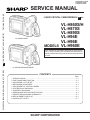
SERVICE MANUAL
S69I1VL-H860S
SERVICE MANUAL
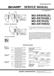
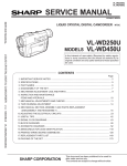
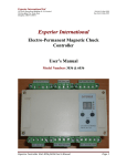
LIQUID CRYSTAL CAMCORDER Hi 8
PAL
LIQUID CRYSTAL CAMCORDER Hi 8
VL-H860S/H
VL-H870S
VL-H890S
VL-H94E
VL-H96E
MODELS VL-H960E
VL-H860S/H/H94E
In the interests of user-safety (Required by safety regulations in some countries) the set should be restored to its
original condition and only parts identical to those specified
be used.
PAL
VL-H870S/H890S/H96E/H960E
MODELS VL-H860S/H/H870S/H890S/H94E/H96E/H960E
CONTENTS
Page
1. SPECIFICATIONS ........................................................................................................................... 1-1
2. PART NAMES AND FUNCTION ...................................................................................................... 2-1
3. DISASSEMBLY OF THE SET .......................................................................................................... 3-1
4. MECHANISM ADJUSTMENT .......................................................................................................... 4-1
5. ADJUSTMENT OF VCR AND CAMERA .......................................................................................... 5-1
6. SYSTEM BLOCK DIAGRAMS ........................................................................................................ 6-1
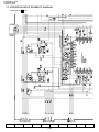
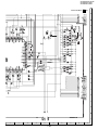
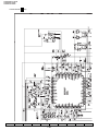
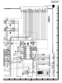
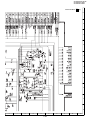
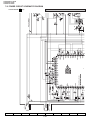
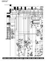
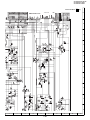
7. SCHEMATIC DIAGRAMS ............................................................................................................... 7-1
8. SEMICONDUCTOR LEAD IDENTIFICATION ................................................................................ 8-1
9. PRINTED WIRING BOARD ASSEMBLIES ..................................................................................... 9-1
10.REPLACEMENT PARTS LIST ...................................................................................................... 10-1
11.PACKING OF THE SET ................................................................................................................ 11-1
SHARP CORPORATION
VL-H870U
VL-H860S/H/VL-H870S
VL-H875U
VL-H890S/VL-H94E
VL-H890U
VL-H96E/VL-H960E
VL-H860S/H/VL-H870S
VL-H890S/VL-H94E
VL-H96E/VL-H960E
1. SPECIFICATIONS
Signal System:
Recording System:
Cassette:
Recording/Playback Time:
Tape Speed:
Pickup Device:
Lens:
Lens Filter Diameter:
Monitor:
Microphone:
Color Temperature Compensation:
Minimum Illumination:
Video Output Level:
Audio Output Level:
Speaker Output:
External Microphone Input:
Power Requirement:
Power Consumption:
Operating Temperature:
Operating Humidity:
Storage Temperature:
Dimensions (approx.):
Weight (approx.):
PAL standard
2 rotary heads, helical scanning system
8 mm video tape, MP type or Hi8 MP, ME type
90 minutes (P5-90)
20.051 mm/second
1/4" (6.4mm, effective size: 4.5 mm) CCD image sensor (with approx.
470,000 pixels including optical black)
22 × power zoom lens (F1.6, f=4.0-88.0 mm) and full-range auto focus
46 mm
3" (7.5 cm) (VL-H860S/H/H870S/H94E/H96E)
3.5" (8.8 cm) (VL-H890S/H960E)
full-color LCD screen (TFT active matrix)
Electret stereo microphone
Auto white balance with white balance lock
5 lux* (with gain-up, F1.6)
1.0 Vp-p 75-ohm unbalanced
–8 dBs, impedance less than 2.2 kohms
200 mW
3.5 mm diameter mini-plug, –66 dBs, output impedance 6.8kohms, DC
4 V, for plug-in-power microphone use
DC 7.4V
4.95W (VL-H860S/H/H870S/H94E/H96E)
5.3W (VL-H890S/H960E)
(during camera recording in full auto mode with zoom motor off, Extend
Zoom, DIS and Snapshot functions off, and backlight in normal mode)
0°C to + 40°C
30% to 80%
–20°C to +60°C
180 mm (W) × 112 mm (H) × 107 mm (D)
740g (VL-H860S/H/H94E)
760g (VL-H870S/H96E)
765g (VL-H890S/H960E)
(without battery pack, lithium battery, video cassette, and lens cap)
AC Adapter UADP-0304TAZZ
Battery Pack BT-L241
DC Output: 7.4 V
Dimensions (approx.): 40 mm (W) × 43 mm (H) ×
54 mm (D)
Weight (approx.): 97 g
Power Requirement:
DC Output:
Power Consumption:
Dimensions (approx.):
AC 110-240 V, 50/60 Hz
9.0 V
15 W
68 mm (W) × 37 mm (H) ×
130 mm (D)
Weight (approx.): 230 g
Specifications are subject to change without notice.
* Minimum illumination: Since there is no widely accepted testing procedure for determining minimum
illumination capability, lux ratings are comparable only between models from the
same manufacturer
1-1
VL-H870U
VL-H860S/H/VL-H870S
VL-H875U
VL-H890S/VL-H94E
VL-H890U
VL-H96E/VL-H960E
VL-H860S/H/VL-H870S
VL-H890S/VL-H94E
VL-H96E/VL-H960E
2. PART NAMES AND FUNCTION
For details on the use of each control.
2-1
VL-H870U
VL-H860S/H/VL-H870S
VL-H875U
VL-H890S/VL-H94E
VL-H890U
VL-H96E/VL-H960E
VL-H860S/H/VL-H870S
VL-H890S/VL-H94E
VL-H96E/VL-H960E
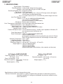
3. DISASSEMBLY OF THE SET
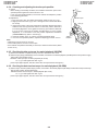
3-1. DISASSEMBLY OF THE VCR PARTS
Note:
Before removing the cabinet, turn off the power supply, and ascertain that the battery has been removed.
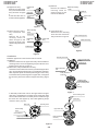
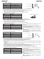
<1. Removal of the Cabinet L>
(i)
(1) Slide the VCR lid knob in the arrow direction, open the VCR (5) Remove the screws (i)XiPSN20P04000(2pcs.).
lid.
L.Cabinet
FPC connector
(b)
(2) Remove the screws (b)LX-HZ0018TAFF(2pcs.).
(6) Close the VCR lid.
(7) Lift about half of the L.Cabinet parts in the arrow direction,
remove the FPC connector.
(i)
(8) Remove the outside charging battery connector.
(d)
(3) Turn the Camera section, and remove the screws
(i)XiPSN20P04000(1pc.), (d)XiPSF20P04000(1pc.).
A.V.terminal FPC
(i)
(4) Remove the A.V.terminal cover and the screws
(i)XiPSN20P04000(3pcs.).
(9) Remove the A.V.terminal FPC.
Note:
The FPCs and the wires of process (7), (8), and (9) are connecting with the L.Cabinet, and remove the L.Cabinet while it is
floating from the main body.
If the L.Cabinet is drawed violently, they have some apprehensions of snap off the wires.
3-1
VL-H870U
VL-H860S/H/VL-H870S
VL-H875U
VL-H890S/VL-H94E
VL-H890U
VL-H96E/VL-H960E
VL-H860S/H/VL-H870S
VL-H890S/VL-H94E
VL-H96E/VL-H960E
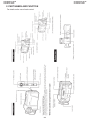
(f)
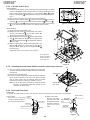
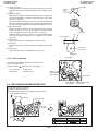
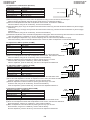
<2. Remove the Tripod Angle.>
(d)
Main PWB
(f)
(f)
Tripod Angle
Microphone connector
(3) Remove the Microphone connector.
Remove the main PWB fixing screws (f)XiPSD20P03000(3pcs.).
Lift the main PWB in the arrow direction and remove the
connection "B to B".
<5. Removal of the main P.W.B>
(d)
Lithium connector
(1) Remove the screws (d)XiPSF20P04000(3pcs.), pull the Tripod Angle.
<3. Removal of the LCD unit>
LCD unit
Camera FPC
Main PWB
(b)
Inverter transformer
(d)
(1) Remove the Camera FPCs(2pcs.) are connected with main
PWB and the Camera section, and remove the Lithium
connector.
C
Remove the battery
connector
B
A
Remove EJECT TURN
S.W. connector
(1) Remove the FPCs from connectors A, B and C.
("C" isn't used with VL-H860S/H94E/EX.)
(2) Remove the screws (d)XiPSF20P04000(1pc.) and (b)LXHZ0018TAFF(1pc.).
<4. Removal of the V.Cabinet>
(b)
(2) The same as process 4., remove the battery connector in the
reverse side of PWB and EJECT TURN S.W. connector, and
disconnect the Tilt section and main PWB.
<6. Removal of the Cabinet and Mechanism>
(b)
Remove the Lithium
Holder
(e)
V.Cabinet
(1) • Firstly, remove the Lithium Holder.
• Turn to upside the surface of V.lid, remove the
V.Cabinet fixing screw (b)LX-HZ0018TAFF(1pc.).
(d)
(e)
(1) Remove the screws (b)LX-HZ0018TAFF(1pc.), (d)
XiPSF20P04000(3pcs.) and (e)LX-BZ0191TAFD(2pcs.).
(d)
Side angle
(b)
(e)
(g)
(2) Turn the Camera section to right angle, remove the Tilt side
fixing screws (g)LX-HZ0045TAFF(2pcs.), the bottom side
screw (b)LX-HZ0018TAFF(1pc.), open the VCR lid, and
remove the slant wise screw (d)XiPSF20P04000(1pc.).
Note:
The Tilt section is setting with the parts of the Camera section .
(Never remove the parts of Camera section only.)
(2) Pull the Mechanism from K.S.V.Cabinet, remove the screw
(e)LX-BZ0191TAFD(1pc.) and the side angle.
3-2
VL-H870U
VL-H860S/H/VL-H870S
VL-H875U
VL-H890S/VL-H94E
VL-H890U
VL-H96E/VL-H960E
VL-H860S/H/VL-H870S
VL-H890S/VL-H94E
VL-H96E/VL-H960E
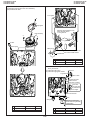
<7. Removal of the cassette compartment lid>
B
C
C
Note:
When fixing the cassette compartment lid, first engage the
claws A and B, and then engage the claws C and D, verify that
the four claws (A, B, C and D) of the cassette compartment lid
are securely engaged as shown in the view below.
A
B
D
E
Claw C
A
Claw B
View E
Claw A
D
Claw D
View F
F
(1) Using the slotted precision screwdriver, push and turn the two claws (C and D) which fasten the cassette compartment lid, and
the cassette compartment lid will be removed from the hook area of the cassette component.
(2) Turning the cassette compartment lid in the arrow direction, lift it, and the claws A and B will be disengaged to remove the
cassette compartment lid.
Note:
Take care to prevent breaking the claws of the cassette compartment lid.
<8. Removal of LCD Unit>
(3)
(D)
(L)
(B)
(J)
(2)
(C)
(E)
(A)
(4)
(K)
(F)
(G)
(H)
(a)
(A) Touch Panel Fitting A
(1)
(B) Touch Panel
(C) LCD Panel
(D) LCD Holder A
(I)
(E) DBEF Sheet
(F) Prism Sheet
(G) Diffusion Sheet
(H) Light Guide Plate
(I) Reflection Polarizing Sheet
(J) Lamp Inverter
(K) LCD Holding Sheet
(L) Touch Panel Sheet
• At the time of removing from the LCD Holder A(D), and take off the hooks(1)(2pcs.).
• At the time of removing from the LCD Holder A(D), take off (K), remove the FPC from
the hooks(3)(2pcs.), disengage the claw(2), and slide the LCD Panel(C) in the (a)
direction to remove the LCD Holder A(D).
• At the time of removing from the LCD Holder A(D), remove the claws(4)(2pcs.).
•As for VL-H860S/H/H94E (A) (B) (L) (E) isn't used.
` Refer to the item CABINET EXPLODED VIEW about other parts.
3-3
VL-H870U
VL-H860S/H/VL-H870S
VL-H875U
VL-H890S/VL-H94E
VL-H890U
VL-H96E/VL-H960E
VL-H860S/H/VL-H870S
VL-H890S/VL-H94E
VL-H96E/VL-H960E
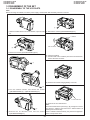
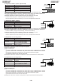
3-2. REMOVAL OF THE CAMERA PARTS
Note:
Before removing the Cabinet, turn off the power supply,and ascertain that the battery has been removed.
(b)
(d)
(c)
(c)
(a)
(c)
(b)
Pull out
(d)
Pull out
Camera front cabinet
1. Remove the screws (b)LX-HZ0018TAFF(1pc.), (a)LX-HZ
0018TAFN(1pc.),(c)LX-HZ0045TAFN(1pc.)and
(d)XiPSF20P04000(1pc.), pull out the Front cabinet.
Speaker connector
(g)
4. Remove the screws(b)LX-HZ0018TAFF(1pc.),(c)LXHZ0045TAFN(2pcs.) and (d)XiPSF20P04000(1pc.),pulling out
the Camera rear Cabinet, and remove the Speaker connector.
Camera rear grip cover
Remove
(c)
(g)
2. Remove the screws (g)LX-HZ0045TAFF(2pcs.) and the Camera rear grip cover .
Battery catcher connector
Pull out
Tilt Frame C
Connector
Claw
3. Remove the connector.
5. Remove the screw (c)LX-HZ0045TAFN(1pc.) and pull out
the Tilt Frame C.
Pull out the Tilt Frame C. at right angle, because of closing the
claw.
Then, pull out the battery catcher connector from the Tilt
Frame C.
3-4
VL-H870U
VL-H860S/H/VL-H870S
VL-H875U
VL-H890S/VL-H94E
VL-H890U
VL-H96E/VL-H960E
VL-H860S/H/VL-H870S
VL-H890S/VL-H94E
VL-H96E/VL-H960E
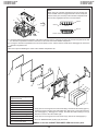
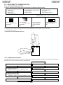
Remove
Open
(c)
Remove
Tilt connector
Open
6. Remove the Tilt connectors(2pcs.) as the Tilt Frame C. are
floating in the air.
Note:
Take care to prevent breaking the FPC when the Tilt Frame C.
is removing from them.
(g)
7. Remove the screws (g)LX-HZ0045TAFF(1pc.) and (c)LXHZ0045TAFN(1pc.), opening the claws(2pcs.) to outward,
remove the Lens unit with Camera P.W.B.
Screws
a
LX-HZ0018TAFN M2x6 Tapping Screw, Silver
b
LX-HZ0018TAFF
c
LX-HZ0045TAFN M2x4 Tapping Screw, Silver
M2x6 Tapping Screw, Black
d
XiPSF20P04000
e
LX-BZ0191TAFD
M2 Special Screw
f
XiPSD20P03000
M2x3 Screw
g
LX-HZ0045TAFF
M2x4 Tapping Screw, Black
h
LX-HZ0013TAFF
M1.7x6 Tapping Screw, Black
i
XiPSN20P04000
M2x4 Small Screw, Silver
j
LX-HZ0050TAFN M1.7x4 Tapping Screw, Silver
k
LX-BZ0236TAFD
M2x8 Screw
l
XiPSF20P03000
M2x3 Screw, Black
M2x4 Small Screw, Black Zinc Plating
3-5
VL-H870U
VL-H860S/H/VL-H870S
VL-H875U
VL-H890S/VL-H94E
VL-H890U
VL-H96E/VL-H960E
VL-H860S/H/VL-H870S
VL-H890S/VL-H94E
VL-H96E/VL-H960E
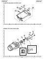
3-3. REPLACEMENT OF CCD SENSOR
3-3-1. Before replacement
1) The CCD image sensor is more sensitive to electrostatic breakage than C-MOS LSI. Therefore sufficient means to prevent
electrostatic damage must be taken when it is replaced.
• Ground the soldering iron.
• Ground also the human body, using the wrist strap(through an 1 Mohm resistor).
• Until the CCDsensor is mounted on the PWB, fit it to the conductive sponge, and short-circuit the foot lead.
2) Take utmost care so that the surface glass of CCD sensor and optical filter are not contaminated and damaged. If any contamination
is found, for example fingerprint, wipe it off with silicon paper or clean chamois skin.
3) When replacing the CCD sensor, use the antistaic grounded soldring iron, and perform quickly soldering.
1
7
Lot No. (Max 7)
Control No.
Week manufactured
Year manufactured
I C X 2 0 9
A K
14
8
3-3-2. Removal of CCD
1) Unsolder the CCD sensor leads from the sensor PWB.
2) Take out the sensor PWB.
3) Remove the two screws (b), and remove the sensor holder and CCD sensor.
3-3-3. Mounting of CCD
1) Place the lens unit upright (since the CCD sensor mount ID faces upward, care must be taken so as not to damage the front lens of
unit), put the crystal filter first and then the dust protection rubber into the CCD holder of lens unit. Set the crystal unit with its thin side
toward the lens unit.
2) Place the CCD sensor so that the its No. 1 pin is at the right lower (Positioning hole to be at right), and put the CCD sensor into the
CCD holder. For smooth and tight fitting, press the right lower part of back of CCD sensor, and then press the left upper part.
Note: Pay attention to the direction of CCD sensor.
3) Place the sensor holder so that its two round markings be visible, and fix the sensor holder with the two screws ((b)LX-HZ0013TAFF).
4) Mount the sensor PWB so that the CCD sensor leads go thorough the PWB holes.
5) Solder the CCD sensor lead to the sensor PWB.
(b)
Note: Take care not to apply excessive heat.
Sensor Holder
CCD Sensor
Crystal
Rubber
The mark must be on
this face.
Lens
Side
CCD
Side
Mark
The THIN SIDE
faces the lens
3-6
VL-H870U
VL-H860S/H/VL-H870S
VL-H875U
VL-H890S/VL-H94E
VL-H890U
VL-H96E/VL-H960E
VL-H860S/H/VL-H870S
VL-H890S/VL-H94E
VL-H96E/VL-H960E
4. MECHANISM ADJUSTMENT
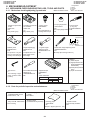
4-1. MECHANISM CHECKING/ADJUSTING JIGS, TOOLS AND PARTS
4-1-1. Mechanism checking/adjusting jigs and tools
1. Cassette torquemeter
for PB
2. JiG8T-012
3. CV
* (10 g·cm/25 g·cm)
1. Cassette torquemeter
for VS-REW
2. JiG8T-032
3. CV
* (50 g·cm/25 g·cm)
<Note: The entries of list>
1. Torque gauge
2. JiGTG0045
3. CN
* For measurement of
loading brake torque
Configuration
1. Name
2. Part No.
3. Code
* Model, Uses Remarks
1. Torque gauge head
1. Torque driver
2. JiGTH-MX7U
(1.5 kg·cm)
3. BS
2. JiGTD1500RT0H
* For torque gauge listed 3. CB
left
Tolerance±0.1
2
1.8
4
1. Master plane
2. JiGMP-MX7U
3. CG
1. Height adjusting jig
2. 9DAGH-E31S
3. BM
* For adjustment of Tu guide * For adjustment of Tu
height, Si roller height and guide height and Si
checking of reel disk height roller height
1. Tu guide height
adjusting driver
2. 9EQDRiVER-V712
3. BL
1. Guide roller height adjusting driver
2. JiGDRiVERHMX7U
3. BU
* Bit shape (See the figure above.)
<Others>
(1) Slide calipers
(2) High-precision screwdrivers (Phillips head,
slotted head)
(3) Radio pliers (with thin
jaws)
(4) A pair of tweezers
1. Hex wrench
1. Tension Band and Plate 1. Alignment tape
3. —
Adjusting Jig
2. VR2DBOPS
* For loosening or tight- 2. JiGDRiVERMX7U2
3. BT
ening of Motor stator 3. BN
TAPE CONTENTS
(1.3mm)
VIDEO IMAGE
MONOSCOPE
Edge
thickness 0.5
AUDIO
TIME
L-CH 400Hz
30MIN
R-CH 1,000Hz
4-1-2. Parts for periodic inspection and maintenance.
<Note: The entries of list>
Configuration
1. Name
2. Part No.
3. Code
* Model, Uses Remarks
1. Oil
COSMOHYDRO HV100
* Cosmo Oil Co., Ltd.
1. Screw locking agent
(1401B)
* Three Bond
1. Greases
1. Cleaning liquid
1. Superfine swab
(Industrial-use ethyl alcohol) 1. Cleaning paper
2. JiGDUSPER
* Commercially available
3. AP
item
* Dusper ∑ (Sigma) (Ozu Co., Ltd.)
Morycoat YM-103/X5-6020
* Dow Coaning
4-1
VL-H870U
VL-H860S/H/VL-H870S
VL-H875U
VL-H890S/VL-H94E
VL-H890U
VL-H96E/VL-H960E
VL-H860S/H/VL-H870S
VL-H890S/VL-H94E
VL-H96E/VL-H960E
4-2. ITEMS AND TIMINGS OF INSPECTION AND MAINTENANCE
The mechanism of VCR needs the following periodic inspection and maintenance in order that it maintains its high quality. Also,
after the machine is repaired, execute the following maintenance and checks regardless of how long it has been used.
4-2-1. Inspection and maintenance list
Checking/Maintenance point
500
Usage time (hrs.)
1,000 1,500 2,000
Possible symptom
encountered
3,000
Tape travel system
• Lateral noise
• Unclean head
• Screen shaking
Tape travelling route
(Refer to Section)
Drum (Refer to Section)
• Improper S/N ratio
• No color appears.
Video head
Remarks
Rollers
• If abnormal rotation or deflection (significant) is
found, replace the roller.
Other than rollers
• Clean the tape contacting
areas. Be sure to use the
specified cleaning agent.
★
★
★
• Tape does not run.
• Tape slackens.
• Screen shakes.
• Replace if failure is found.
Relay Pulle shaft
Pulle gear shaft
∆
∆
∆
• Abnormal sound
Drive gear shaft
∆
∆
∆
• Apply oil.
(Oil : COSMOHYDRO
HV100)
Note:
After oil is applied to the
drive gear shaft, slightly
wipe it off with swab.
• Not ejectable
• The specific mode cannot
be set.
• Replace if failure (abnormal sound) is detected.
Timing belt
Pinch roller
Capstan D.D. motor
Driving system
★
Loading motor
Performance check
Abnormal sound
★
PB/VS-REW take-up torque
PB/VS-REW back tension torque
Tu brake
★
★
★
★
★
★
★
★
★
★
★
★
★
★
★
• If conformance to the
standard is not ensured,
replace part.
HC (Head Cleaner)
Oil: COSMOHYDRO HV100
Greases: MORYCOAT YM-103/X5-6020
Screw locking agent: THREE BOND 1401B
Cleaning liquid: Industrial-use ethyl alcohol
: Replace.
: Clean.
∆ : Apply oil.
★ : Check.
Oil
4-2-2. Notes and cautions
(1) Any cut washers, once removed for parts replacement or for other
reason, must be replaced with new ones.
(2) The mechanism of this VCR does not involve any volume adjustment.
If the specified range is not satisfied, either cleaning or replacing the
parts is required.
(3) Oils
a) Be sure to use the specified oils (different viscosity may cause
troubles).
b) For the bearings, be sure to use oil that is free form dust and other
foreign substances. (Dust or foreign substance contained in the oil
may cause wear or seizure of the bearings.)
c) A drop of oil represents the amount of oil which is held on the needle
top as shown in the figure 1.
(4) The circuit repair must be executed without removing the V frame.
(5) For operating the mechanism alone, actuate it with the motor. The
terminal-to-terminal voltage must be DC4V or less.
(6) When installing the cassette control, press the part A shown in Figure
2.
*Do not press other parts.
(7) Take care so that the whole mechanism is not deformed.
Diameter φ1.5 or less
Figure 1
A
4-2
Figure 2
VL-H870U
VL-H860S/H/VL-H870S
VL-H875U
VL-H890S/VL-H94E
VL-H890U
VL-H96E/VL-H960E
VL-H860S/H/VL-H870S
VL-H890S/VL-H94E
VL-H96E/VL-H960E
4-3. MECHANISM CHECKS AND ADJUSTMENTS
The description given below relates to the general field services, but does not relate to the adjustment and replacement that require
high level equipments, jigs, and technical skills.
In order to maintain the initial characteristics of the machine, it is necessary to execute the maintenance and check and to prevent
damage to tapes and other parts. For adjustments which need jigs, be sure to use the jigs.
Notes and cautions
(1) For mechanism checks and adjustments, be sure to use the AC adapter as the power supply.
(2) For running the tape, be sure to install the cassette control ass’y in advance. (If the cassette control ass’y is to be removed
subsequently after its installation.)
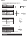
4-3-1. Checking the reel disk height
(1) Remove the cassette control ass’y.
(2) Taking due care not to let the master plane touch the tape running areas such as the drum and the guide rollers, position the
master plane so that the two guides (A and B in the figure 1) are set in the holes of master plane, then properly set it in the
mechanism.
(3) Using the slide callipers or the like, check that the distance from the upper surface of master plane to the reel support surface
of the S/Tu reel disk is within the specified range. (Figure 2)
Note:
When measuring, do not apply excessive force to the reel support surface of reel disk.
(4) If the measurement is not within the specified range, replace the reel disk ass’y.
(5) Check the items (2) to (4) above in the following two modes.
a) Standby mode
b) Playback (recording) mode
A
Figure 1
4.4 ± 0.15
Reel support surface
4.4 ± 0.15
B
Figure 2
4-3-2. Checking the take-up torque for playback (recording)
(1) Set the torque cassette (JiG8T-012) in position, and check in the SP-mode recording mode (tape recorded in SP mode) that
the torque at the tape taking-up side is within the standard range.
Standard of take-up torque for SP-mode recording (playback)
9 ± 3 g·cm with ripples less than 4 g·cm
(If the torque ripples appear, read the center value of torque between the ripples.)
4-3-3. Checking and adjusting the back tension torque for playback (recording)
(1) Checking
1) Set the torque cassette (JiG8T-012) in position, and check in the SP-mode recording mode
(tape recorded in SP mode) that the torque at the tape supply side is within the standard
range.
Standard of back tension torque for SP-mode recording (playback):
8 ± 2 g·cm with ripples of less than 2 g·cm
(Torque ripple must be within 8 ± 2g·cm)
(2) Adjustment
1) If the back tension torque is not within the standard range, adjust the tension spring hooking
position. If the back tension is too high, hook the spring in the direction A. If the back tension
is too low, hook the spring in the direction B.
Note:
1. After back tension torque adjustment be sure to check the tension pole position.
4-3
A
B
VL-H870U
VL-H860S/H/VL-H870S
VL-H875U
VL-H890S/VL-H94E
VL-H890U
VL-H96E/VL-H960E
VL-H860S/H/VL-H870S
VL-H890S/VL-H94E
VL-H96E/VL-H960E
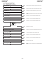
4-3-4. Checking and adjusting the tension pole position
(1) Check
When winding of P5-90 tape is started, check whether the tension pole is in the
specified position against Si roller as shown or not.
If it is not in the specified position, remove the cassette and adjust the position
in the following procedure.
(2) Adjustment
1. Don’t set up any tape, and select the PB mode. (Refer to Item 4-5-1-(4).)
2. Slightly loosen the screw (a) (to such a strength as the T band holder B can
be moved).
3. If the tension pole is in the inner position than specified, dislocate the T band
holder B in the arrow (A) direction and if it is in the outer position, dislocate it
in the arrow (B) position. Then, tighten the screw (a). (For reference, dislocate
it 0.4 to 0.8 mm outer from the position specified above.) For the position
adjustment, it is convenient to use the position adjustment screwdriver
(JiGDRiVERMX7U2). (Set it in the hole (C).)
4. Check the position in the “(1) Check” procedure described above.
5. If it is not in the specified position, repeat the adjusting procedure 1 thru 3.
Note:
• Tightening torque of screw (a) 70 mN·m
• To check the position, be sure to run the tape.
• If the cassette compartment assembly is removed, it makes the work easier. (Refer
to Item 4-5-3.)
0
3 – 0.5
Si roller
Tension pole
Hole (C)
(B)
(A)
Screw
T Band (a)
Holder B
4-3-5. Checking the take-up torque for rewind playback (VS-REW)
(1) Remove the cassette compartment ass'y and set to the sensor OFF mode.
(2) Set the torque gauge (JiGTG0045) on the S reel disk, and check in the rewind playback (VS-REW) that the torque at the supply
side is within the specified range.
Standard of take-up torque in rewind playback (SP mode)
31 ± 5 g·cm with ripples less than 5 g·cm.
(If the torque ripples appear, read the center value of torque between the ripples.)
4-3-6. Checking the back tension torque for rewind playback (VS-REW)
(1) Set the torque cassette (JiG8T-032) in position, and check in the rewind playback (VS-REW) mode that the torque at the tape
take-up side is within the specified range.
Standard of back tension torque in rewind playback (SP mode):
14 ± 5 g·cm with ripples less than 5 g·cm
(If the torque ripples appear, read the center value of torque between the ripples.)
4-4
VL-H870U
VL-H860S/H/VL-H870S
VL-H875U
VL-H890S/VL-H94E
VL-H890U
VL-H96E/VL-H960E
VL-H860S/H/VL-H870S
VL-H890S/VL-H94E
VL-H96E/VL-H960E
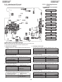
4-4. ADJUSTMENT OF MECHANISM TAPE TRAVEL SYSTEM
Sup tilted pole
4-4-1. Preparation for adjustment
Sup GR
(1) Clean the tape running areas (guide poles, rollers, drum,
Capstan shaft, Pinch roller) (Figure 1)
Si roller
(2) Connect the oscilloscope to the following TPs.
RF output ..... TL7406
H-SW-P ....... TL7446
GND ............. TL7452
(3) Playback the alignment tape (VR2DBOPS).
Tension pole
(4) Ascertain that each guide is free from remarkable curl.
(5) Ascertain that the RF waveform of inlet and outlet sides is flat
on the oscilloscope (Figure 2, (a)). Unless the waveform is
flat, (Figure 2, (b), (c)), make an adjustment as follows.
,,
,,
,, ,,,,
,,,,
,,,,
,,,,
,,,,
Tu tilted pole A
Tu GR
Tu tilted pole B
Capstan shaft
Tu guide
Drum
Pinch roller
Reel
Tape travel system (Figure 1)
4-4-2. Adjusting the Sup GR and Tu GR
(1) Turn the Sup and Tu guide rollers to get the flat waveform at the inlet and outlet sides.
Inlet side
Outlet side
(c) Outlet side
waveform is disturbed.
(b) Inlet side
waveform is disturbed.
(a) Normal
Figure 2
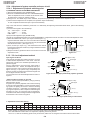
4-4-3. Adjusting the Si roller height
Height adjusting jig
Upper flange
After replacement of Si roller preset and adjust the Si roller
height.
(1) Si roller height presetting
Adjust the height from the upper surface ofmechanism chassis to the upper surface of lower flange with the aid of jig. Then
lower it by 90° (clockwise).
Master plane
(JiGMP-MX7U)
Lower
flange
Figure 3
(2) Adjusting the Si roller
1 Playback the tape to set the V/SR mode.
2 Ascertain that the tape is not folded on the lower flange (B) of Si roller. (Figure 4)
If tape folding is found, turn the upper flange (A) of Si roller with the driver (clockwise) to eliminate the folding.
3 Playback the alignment tape (VR2DBOPS).
4 Adjust the Sup GR and Tu GR by the procedure described in section 4-2 above.
5 After V/S F,R perform playback so as to ascertain that the waveform rises horizontally within 2 seconds.
6 Unless the normal waveform is obtained (Figure 5), turn counterclockwise the upper flange (A) of Si roller, and repeat the step
(5) above. Repeat the steps (5) and (6) until the normal waveform is obtained. At this time ascertain that the inlet travel does
not change in the normal playback state. If any change is found, adjust the Sup GR, and redo the step (5).
Si roller
Rise waveform
Upper flange (A)
REV
OK
Playback
REV
NG
Playback
REV mode
Lower flange (B)
Tape must be free from foldeng.
Figure 5
Figure 4
4-5
VL-H870U
VL-H860S/H/VL-H870S
VL-H875U
VL-H890S/VL-H94E
VL-H890U
VL-H96E/VL-H960E
VL-H860S/H/VL-H870S
VL-H890S/VL-H94E
VL-H96E/VL-H960E
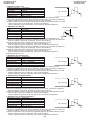
4-4-4. Adjusting the Tu guide
After replacement of Tu guide preset and adjust the height.
(1) Tu guide height presetting (Figure 6)
Adjust the height from the upper surface of mechanism chassis to the
upper surface of lower flange with the aid of jig.
Height setting jig
Master plane
(JiGMP-MX7U)
Upper flange
Lower
flange
Figure 6
(2) Adjusting the Tu guide (Figure 7)
1 Playback the alignment tape (VR2DBOPS).
2 Check that the tape runs at the same height near the capstan shaft in case of
V/S F and V/S R.
3 If the tape running position in case of V/S R is higher than the tape running
position in case of V/S F, turn clockwise the Tu guide nat.
If the tape running position in case of V/S R is lower than the running position
in case of V/S F, turn counterclockwise the Tu guide nat.
Capstan shaft
Nat
Pinch roller
Figure 7
4-4-5. Checking the V/S F and R waveforms (Figure 8)
(1) Playback alignment tape (VR2DBOPS), and set the V/S R mode. At this time
ascertain that the waveform crest pitch is kept constant for more than 5 seconds.
(2) Set the V/S F mode. At this time ascertain that the waveform crest pitch is kept
constant for more than 5 seconds.
Unless the constant pitch is obtained, execute the checks of Section 4-2, 3, and
4.
a
b
c
d
a b c d
Figure 8
4-4-6. Checking after adjustment
(1) Envelope check
1 Playback the alignment tape (VR2DBOPS).
2 Ascertain that the envelope maximum to minimum ratio is 65% or more. (Figure 9)
3 Ascertain that the waveform does not change remarkably. (Figure 10)
C
A
E MIN E MAX
C
Figure 9
E MIN
E MAX
C 1/8A
Figure 10
65 (%)
(2) Rise check
1 Playback the alignment tape (VR2DBOPS).
Capstan shaft
Tu guide
2 Once eject the cassette, and then load it again.
3 Set the playback mode, and ascertain that the RF waveform rises horizontally
within 2 seconds. At this time ascertain that there is no tape slackness near
the pinch roller.
Tu GR
Tape slackness
4 After V/S F, R and FF/REW execute playback, and ascertain that the RF
waveform rises horizontally within 2 seconds. At this time ascertain that there
is no tape slackness near the pinch roller.
Tension pole
Figure 11
Sup tilted pole
(3) Checking the tape travel
1 When the tape is played back, ascertain that tape lift and tape curl of 0.3 mm
or more do not occur at the lower flange of Si roller, upper flange of Sup GR,
upper flange of Tu GR, and upper/lower flange of Tu guide.
Drum
Si roller Sup GR
Tu GR
2 In case of V/S F and R ascertain that no curl is found at each flange.
Drum
Tu guide
Tu tilted pole Pinch roller
Figure 12
4-4-7. Checking and adjusting the playback switching point
Refer to the description of playback switching point adjustment in section of VCR circuit adjustment.
4-6
VL-H870U
VL-H860S/H/VL-H870S
VL-H875U
VL-H890S/VL-H94E
VL-H890U
VL-H96E/VL-H960E
VL-H860S/H/VL-H870S
VL-H890S/VL-H94E
VL-H96E/VL-H960E
4-5. MECHANISM ASSEMBLING AND PARTS REPLACEMENT
(DISASSEMBLING AND ASSEMBLING)
Below is given an explanation of assembling of mechanism and its parts replacement.
The removal of cabinet and Circuit Board is explained in the relevant service manual.
Notes
1 After removal of cut washers be sure to replace them with new ones.
2 Do not place the mechanism upside down on the table. Otherwise, the mechanism part may be deformed or damaged, resulting
in malfunction.
3 When assembling, take care so that screw, washer or other foreign substance do not enter. Otherwise mechanism malfunction
may occur.
4 Be sure to use the specified cleaning liquid, oil, grease and screw lock as listed below. Otherwise mechanism malfunction may
occur.
Oil:
Cosmo Oil Co., Ltd.
COSMOHYDRO HV100
Greases:
Dow Coaning
MORYCOAT YM-103/X5-6020
Screw lock:
THREE BOND
1401B
Cleaning liquid: Industrial-use ethyl alcohol
4-5-1. Mechanism modes
To actuate the mechanism, apply DC3 to 4V to the L motor. At this time the L motor connector must have been disconnected in advance.
Below is given an explanation of the mechanism mode necessary for mechanism check, adjustment and replacement.
(1). EJ (Eject) mode (See Figure 1)
(2). S/B (Standby) mode (See Figure 2)
In this mode, it is mechanically positioned to eject the
cassette. It is the position where the EJECT lever is moved
the farthest in the direction A in the S/B mode. (In this
mode, the cassette compartment assembly can not be
locked.)
Slide
chassis
A
A
When the cassette is loaded, the mechanism is set to the
S/B mode. In this mode the slide chassis is most far from
the drum. In this mode the Eject lever is in position shown
in Figure 2 (in position where the cassette control ass’y
can be locked).
Slide
chassis
EJECT
Lever
EJECT
Lever
EJ mode
S/B mode
Figure 2
Figure 1
(3). STOP mode (See Figure 3)
(4). PB mode (See Figure 4)
In the STOP mode the S.T pole base is depressed in the
STOP position (or Rec Lock position in CAMERA mode),
and the S brake is in contact with the S reel disk.
S pole base
In this mode, it is positioned for the replay, record and so
on. It is the mechanical position where the pinch roller is
pressed against the capstan shaft to make the pinchpressing spring the most longest.
T pole base
Capstan
shaft
Pinch
Spring
S reel disk
Pinch roller
S brake
STOP mode
Figure 3
PB mode
Figure 4
4-7
VL-H870U
VL-H860S/H/VL-H870S
VL-H875U
VL-H890S/VL-H94E
VL-H890U
VL-H96E/VL-H960E
VL-H860S/H/VL-H870S
VL-H890S/VL-H94E
VL-H96E/VL-H960E
4-5-2. Cassette control ass’y
<Disassembling>
(1) Set the unit to the EJECT mode, and let the housing stand upright. Or set the
unit to the STANDBY mode, press the lock lever in the arrow direction, and
let the housing stand upright. (See Fig. 5: in the direction a or b ) (When
pushing in the direction a , slightly lift the housing by hand to release the lock
lever.)
(2) Remove the four screws 2 and take out the down guide 3.
(3) Slide the two link support shafts c and the two roller shafts d to the round
openings g on their respective slide chassis slits (two at e and two at f ).
(4) Deflect the roller shafts d a little inward to get them out of the round openings
g on the slide chassis. (Be careful not to deform the inner links.)
Lock Lever
Down Guide
a
c
i
Screw
b
j
Figure 5. Lock lever section
l
<Reassembling>
(1) Set the unit to the STANDBY mode.
(2) Deflect the roller shafts d a little inward, and fit them
into the round openings g on the slide chassis. (Be
careful not to deform the inner links.)
(3) Align the flanges of roller shafts d with the slide chassis
slits f . While sliding the flanges, fit the support shafts
c in the slide chassis slits e , and slide them until they
reach the slits.
(4) Attach the down guide. (While pressing the guide in the
direction i , tighten the screws until the gap j between the down guide 3 and the support shafts c
becomes zero.)
Tightening torque: 70±7 mN·m (0.7±0.07 kg·cm)
4
1
m
m
k
n
c
d
r
d
c
f
e
2
Screw tightening
torque (4 locations)
0.069±0.007 N·m
(0.7±0.07kg·cm)
g
i
3
i
f
2
g
e
2
2
Figure 6
4-5-3. Actuating the mechanism with the cassette control ass’y removed
(1) Turn on the power supply with the cabinet and camera unit
removed, referring to the Service Manual (so as to actuate the
mechanism).
(2) Put the cap on the light guide.
(3) Press the cassette control down switch through the adhesive
tape in the arrow direction so as to turn it on. At this time take
care to avoid contact with the cassette. Keep the switch
pressed (if the switch is turned off, unloading occurs).
Note: To set the Rec mode, press the pin (marked with the
asterisk *) of recognition switch (this operation is not
necessary in other modes).
Cap
Adhesive tape
Cassette control
down switch
Light guide
Recognition switch
*
4-5-4. Drum and Drum base
<Removal>
* To replace the upper drum, be sure to put on gloves. Due care is required so that the drum is not damaged.
(1) Drum base
Remove the 3 mounting
screws as shown in Figure 1,
and remove the drum base.
Mounting
screw
(2) Drum motor stator
Remove the stator
mounting screw with
Earth spring
the hexagonal wrench
as shown in Figure 2,
remove the motor
stator.
Positioning
Drum base
Upper/lower drum ass'y
Phase matching
hole
Motor stator
Stator mounting
screw
Upper/lower
drum ass'y
hole
Figure 1
Figure 2
4-8
VL-H870U
VL-H860S/H/VL-H870S
VL-H875U
VL-H890S/VL-H94E
VL-H890U
VL-H96E/VL-H960E
VL-H860S/H/VL-H870S
VL-H890S/VL-H94E
VL-H96E/VL-H960E
(3) Upper drum ass’y
Remove the upper drum
ass’y from the lower drum
ass'y as shown in Figure
3.
At this time take care so
as not to lose the gap shim.
(5) Balancer
Remove the balancer
mounting screw as
shown in Figure 5, and
remove the balancer.
Upper drum
ass'y
Gap shim
Balancer mounting
screw
Balancer
Lower drum
ass'y
Upper drum
ass'y
Figure 5
Figure 3
(4) Motor rotor ass'y and rotary transformer rotor
ass'y
Remove the 2 rotor
mounting screws as
shown in Figure 4, and
remove the motor rotor
and the rotary transformer
ass'y.
Rotor mounting
screw
(6) Lower drum ass'y
Remove the FPC mounting
screw from the lower drum
ass'y as shown in Figure 6.
Motor rotor
Positioning
hole
FPC mounting screw
Upper drum
ass'y
Lower drum ass'y
Positioning pin
Figure 6
Figure 4
<Installation>
Mounting screw hole
Install the upper drum in the reverse order of removal.
(1) Balancer
Mount the balancer to the upper drum ass'y with the balancer
mounting screw. The screw tightening torque must be 0.1N·m
(tighting torque 1kg·cm). (Figure 5)
(2) Motor rotor, rotary transformer rotor ass’y
Clean the contact surfaces of rotor ass’y holder and upper drum
ass'y, and ascertain that there are no contamination and flaws.
Next, adjust the phase so that the positioning pin of rotor ass'y
is inserted into the positioning hole of upper drum, and tight fit
the rotor ass'y to the lower surface of upper drum ass'y (Figure
7).
Cleaning (shaded area)
(holder)
Positioning pin
Rotary transformer
rotor
Rotary transformer
Rotor ass'y
Positioning hole
To be aligned with
RTr rotor side position
pin.
Cleaning
Figure 7
In this state put the motor rotor on the upper surface of upper
drum ass'y, and tighten the mounting screw. At this time make
sure that the head screw in the three places is visible through
the motor rotor hole (Figure 8). The screw tightening torque
must be 0.1N·m (1 kg·cm).
Rotor mounting screw
Motor rotor
L ch
Motor rotor
Mounting screw
Upper drum ass'y
Head mounting
screw
Screw relief hole
Upper drum ass'y
Rotary transformer
rotor ass'y
Alignment position (3 pcs.)
R ch
Figure 8
4-9
VL-H870U
VL-H860S/H/VL-H870S
VL-H875U
VL-H890S/VL-H94E
VL-H890U
VL-H96E/VL-H960E
VL-H860S/H/VL-H870S
VL-H890S/VL-H94E
VL-H96E/VL-H960E
(3) Lower drum ass'y
Tighten the FPC mounting screw to the lower drum ass'y. The screw
tightening torque must be 0.08N·m (tighting torque 0.8kg·cm). (Figure 6)
(4) Upper drum ass’y
After fitting the gap shim which was removed when the upper drum
ass'y was dismantled to the shaft of lower drum ass’y, fit the upper
drum ass’y. (Figure 3)
At this time slightly turn the upper drum ass'y by hand to ascertain that
RTr does not scrape. If scrape is found, replace the gap shim with the
gap shim packaged together with the replacement upper drum ass’y.
(5) Drum motor stator
Fit the motor stator to the shaft. Then, apply the preliminary pressure
0.07N·m (0.7kg) to the motor stator, tighten the stator mounting
screw. The tightening torque must be 0.15N·m (1.5kg·cm).
Install the stator so that the chassis line is nearly parallel with the
motor stator straight section when it is installed on the chassis.
(Figure 9)
(6) Drum base
Align the positioning pin, and tighten the screws (3 pcs.).
(7) Drum ass’y
Install the drum ass’y on the main chassis, and tighten the screws (3
pcs.).
(8) Tape guide
Align the positioning pin, and tighten the screw (1 pc.).
Motor stator
Stator set
screw
Chassis line
FPC
Arrange parallel.
Motor stator
circuit board
Figure 9
Lo relay gear
4-5-5. Phase matching
The phase of the following parts must be matched as
shown in the figure below.
(Ascertain that the
marks and round holes align.)
(1) Lo relay gear
(3) Sub-cam
(2) Main cam
(4) Mode switch
Phase
alignment mark
(Round hole)
Mode switch
Phase alignment
mark ( Mark)
4-6. MECHANISM ASSEMBLING METHOD
Phase alignment mark
(Round hole)
(1) Adjust the phase of each part.
(2) Install screws and washers.
(3) Install the segment gear, T arm guide and the M-function
lever. Install the eject lever.
a
T arm guide
Segment gear
M-function lever
Move claw
to rear side.
Move claw to
rear side.
Item
a S Tight M1.4 x 3
B ø0.8-ø3-t0.2
B
4-10
Tightening torque
70mN·m (0.7kgf·cm)
Quantity
1
1
VL-H870U
VL-H860S/H/VL-H870S
VL-H875U
VL-H890S/VL-H94E
VL-H890U
VL-H96E/VL-H960E
VL-H860S/H/VL-H870S
VL-H890S/VL-H94E
VL-H96E/VL-H960E
(7) Install the guide rail assembly taking care to position it
(4) Install the loading block assembly and the capstan motor.
correctly.
(5) Install the drive gear. At this time, pay attention to the
direction of gear. (The small gear must be located in the
B
A
chassis side.)
a
a
A
a
Make sure not deform the arm.
Loading motor
Capstan motor
a
A
a
D
C
Move FF
downwards
Install the
motor under
this plate.
Drive gear
Position the small gear of the drive
towards the chassis.
Item
Tightening torque
A S Tight M1.4 x 2.5
70mN·m
a S Tight M1.4 x 3
70mN·m
Quantity
1
4
(6) Install the guide rail assembly.
A
B
C
D
a
Make sure not to
deform the arm.
Item
Tightening torque
S Tight M1.4 x 2.5
70mN·m
S Tight M1.4 x 4
40mN·m
ø0.8-ø3-t0.2
ø2.1-ø5-t0.25
S Tight M1.4 x 3
70mN·m
Quantity
2
1
1
1
1
Insert the part in the
rail and slide it down.
Align the marks on the parts.
Square Hollow Mark
Triangle Mark
Round Hole
Insert the part in the rail
and slide it down.
Edge A
Su arm Ass'y T Lo arm Ass'y
Segment gear
4-11
VL-H870U
VL-H860S/H/VL-H870S
VL-H875U
VL-H890S/VL-H94E
VL-H890U
VL-H96E/VL-H960E
VL-H860S/H/VL-H870S
VL-H890S/VL-H94E
VL-H96E/VL-H960E
(8) Install the drum assembly in the chassis.
(9) Install the tape guide in the drum assembly.
(10) Install the Si roller.
(11) Install the slide chassis.
T arm guide
B
Tape guide
A
Slide this part towards the T arm.
Place the slide chassis
on the guide rail.
A
Drum assembly
B
A
A
Si roller
B
Roller spring
Main cam pin
B
Insert the main cam pin into the
hole of cam of slide chassis.
Sup reel base
Item
A M1.4 x 1.5 ø4
B M1.4 x 1.5 ø3.5
Chassis drawing
Tightening torque
40mN·m
40mN·m
Quantity
1
3
(12) Install in the following order: T guide lever spring, T guide
lever, pinch lever.
Pinch lever
(13) Install the swing arm.
(14) Install the right guide holder.
Tu guide lever
Attach to hook
Tu guide lever SPR
Attach to hook
Take care of position.
Pinch lever
Stopper
The pinch lever
is positioned on
the stopper.
B
Secure on back side
Claw
Claw
Swing arm
Item
A S tight M1.7 x L5.3
B S tight M1.7 x L2.5
Tightening torque
100mN·m
60mN·m
Take care not to bend the
tension band during assembly
or disassembly.
A
Quantity
3
1
Item
A S tight M1.4 x 2.5
B CW ø0.8-ø3-t0.2
4-12
Tightening torque
70mN·m
70mN·m
Quantity
1
1
VL-H870U
VL-H860S/H/VL-H870S
VL-H875U
VL-H890S/VL-H94E
VL-H890U
VL-H96E/VL-H960E
VL-H860S/H/VL-H870S
VL-H890S/VL-H94E
VL-H96E/VL-H960E
5. ADJUSTMENT OF VCR AND CAMERA
5-1. INITIAL SETTING OF E2PROM IC
5-1-1. E2PROM data alterable ways
1) Set the switch of main body to CAM, and use the remote control (RRMCG0033TASA) for adjustment to turn on the adjustment
mode.
2) VCR adjustment address setting.
V ADJ
0000
“0000” is blinking
After an objective address was established, play key is pushed and set.
In addition, numerical change uses a “REW” or “FF” key.
3) VCR adjustment data setting.
V ADJ
0000 ##
Value of “##” differs by an address.
After an objective data was established, “PLAY” key is pushed and set.
4) When data of other address are changed successively, push “STOP” key, and please repeat operation to 5) from 3).
5) When SW of the substance is turned into off, data are written to E2PROM from systematic microcomputer.
5-1-2. IC703 (E2PROM)
When the IC703 has been replaced, make the following settings and adjustments.
1. Remove the backup battery (CR2025).
2. Turn power switch to CAMERA.
3. Setting up the V ADJ mode as follows.
* After press the CONTINUE key, press the VCR ADJ key on service remote control (RRMCG0033TASA).
4. After setting the above data, clear the V ADJ mode and turn off the power by pull out the battery pack or DC cable.
Neglect about 30 seconds after turned of power, because data of address becomes effective after microcomputer is reset.
Now the setting of data is completion.
address
03 (Specificaton code)
02 (Country code)
H860S H860H H870S H890S H94E H94EW H94EX H96E H96EW H96EX H960E H960EW
data
data
data
data
data
data
data
data
data
data
data
data
28
20
28
28
01
01
01
20
01
01
01
01
00
00
00
00
00
00
00
00
00
00
00
00
Adjustments to follow
Make the system controller servo, VCR, and LCD adjustments according to their respective instructions.
5-1-3. Camera adjustment
When the IC2 has been replaced, make the camera adjustment according to its instructions.
All the camera adjustment data are written in the E2PROM provided on the lens unit. Therefore, when the lens is replaced, the
camera must be adjusted again according to the camera adjusting procedure.
5-2. ADJUSTING THE Y/C, AUDIO AND LCD CIRCUITS ON MODELS WITHOUT A/V IN MODE
(A/V IN MODE SET-UP PRODUCE)
1) Set the switch of main body to CAM, and use the remote control (RRMCG0033TASA) for adjustment to turn on the adjustment
mode.
2) Set up the adjustment address (example : EE mode adjustment address 14). Once this address has been set up, the A/V IN mode (test
mode) is automatically brought and the images appear on the LCD display.
3) Now make the adjustments referring to the instruotions in the manual.
5-3. ADJUSTMENT OF VCR SECTION
5-3-1. Before starting the electric circuit adjustment
• Electric circuit adjustment becomes necessary, in most cases, when any of the wear mechanical parts or the video head has been
replaced. Before starting the electric circuit adjustment, be sure to check that the mechanical parts work well (i.e., the mechanical
parts have all been perfectly adjusted). In case a trouble or troubles are found in the electric circuitry, be sure to pinpoint the cause(s)
by using the measuring instruments described below. After locating the trouble spot(s), then proceed to repair, replacement or
adjustment. Do not change the positions of the controls when adequate measuring instruments are not available.
• In order to implement a higher-density, smaller machine, most of the electric circuit parts used on the Circuit Boards are of smallsized, surface-mounted type. For replacing part(s) as after-sales service, work with a soldering iron as speedily as possible. The
heat resistance of the surface-mounted components is poor, when compared with the larger-sized discrete parts used for television
sets and stationary decks, owning to their small sizes. Therefore, exercise due care to avoid long-time exposure of the pins of these
parts to the heat of the soldering iron which may possibly damage them. Such care should be exercised especially for chip-layer
capacitor replacement. It is advisable to use a temperature-controlled ceramic soldering iron (temperature at the tip: 250°C,
contacting time: less than 5 seconds).
5-1
VL-H870U
VL-H860S/H/VL-H870S
VL-H875U
VL-H890S/VL-H94E
VL-H890U
VL-H96E/VL-H960E
VL-H860S/H/VL-H870S
VL-H890S/VL-H94E
VL-H96E/VL-H960E
< Adjusting the video/LCD section >
• Measuring instruments:
*Color monitor TV set
*Digital voltmeter
*DC power supply
*Audio generator (CR oscillator)
*Alignment tape (JiGWR5-5CSP)
(JiGWR5-8CSE)
(JiGWR5-9CS)
*AC adapter
*Oscilloscope
*Frequency counter
*Signal generator
*AV output cable (accessory)
*Video recording tape
(For Y/C, audio and servo adjustments)
*DC cable (AC adapter accessory)
*Video extension cables
*Vector scope
5-3-2. Servicing the VCR section Adjustment
5-3-2-1. Typical connections
Configuration
<Note: The entries of list> 1. Name 2. Part No. 3. Code
4. Note
* Model, Uses Remarks
<Extension Cable etc.>
1
2
3
4
5
1. Extension Cable
Inverter~VCR (7pin)
2. QCNW-1265TAZZ
3. AX
1. Extension Cable
1. Extension Cable
1. Extension Cable
1. Extension Cable LCD~
MECHA~VCR (70pin)
Camera~VCR (18pin)
Camera~VCR (19pin)
VCR (24pin)
2. QCNW-1534TAZZ
2. QCNW-1270TAZZ
2. QCNW-1381TAZZ
2. QCNW-1382TAZZ
3. BS
3. AY
3. AX
3. BD
6
7
8
9
1. Operation Unit
2. QSW-Z0287TAZZ
3. AW
~1
1. DC-IN Jack Unit
2. QJAKZ0069TAZZ
3. AK
1. AV Jack Unit
2. QJAKZ0070TAZZ
3. AX
1. Extension Cable
Touch Panel (6pin)
2. QCNW-1267TAZZ
3. AX
~2
insulating sleeve
1. Connector fitting and
withdrawing extractor
· Alignment Tape
JiGWR5-5CSP (PAL) ....... Normal 8 TAPE (MONO)
JiGWR5-8CSE (PAL) ...... Hi8 TAPE (MONO)
JiGWR5-9CS (PAL) ......... Hi8 TAPE (STEREO)
* Y/C Audio Alignment
1. Connector fitting and 1. Service remote control
withdrawing tweezers 2. RRMCG0033TASA
3. BT
2. 9EQPiNSET06GE
3. BR
~1 VL-H870/H890/H96/H960
"
(FF) Button" functions to as "DISPLAY-button".
~2 It is unnecessary with the VL-H860/H94.
MECHA
UNIT
4
9
7
8
2
VCR
UNIT
3
6
1
LCD
UNIT
INVERTER
5
5-2
CAMERA
UNIT
VL-H870U
VL-H860S/H/VL-H870S
VL-H875U
VL-H890S/VL-H94E
VL-H890U
VL-H96E/VL-H960E
VL-H860S/H/VL-H870S
VL-H890S/VL-H94E
VL-H96E/VL-H960E
• Types of test modes
TEST No.
1
3
Title
Sensors off
Contents
All sensors but the cassette controller switch, dew sensor and
battery sensor stay off.
Battery sensor’s input voltage put in memory.
Automatic battery sensor
adjustment
Battery adjustment error
display
Battery sensor’s adjustment errors are displayed at the right of
the “past errors” area.
5
6
PASS mode
Camera adjustment mode
Track shift mode (1/4 shift)
Camera adjustment mode
7
8
VCR adjustment mode
Automatic switching point
adjustment (STOP ADJ)
VCR adjustment mode
Play standard tape and call this mode. Switching point is
automatically adjusted.
4
Sensor on/off
All sensors on
All but sensors
on
All sensors on
[VCR
interrupted]
1 When the battery adjustment mode is selected from the camera adjustment mode with a cassette with the erase protection tab,
the VCR is automatically put in the REC mode.
• Below discussed are these seven test modes.
1 [TEST No. 1]
Sensors off mode
All the sensors, except for the cassette controller switch, dew sensor and battery sensor, stay off. This enables
to bring the VCR in the loading mode without tape. The VCR/camera performance can now be checked with no
tape inside.
2 [TEST No. 3]
Automatic battery alarm adjustment
Used to automatically adjust the voltage level which makes the “battery” appear on the LCD display.
3 [TEST No. 4]
Battery alarm check/error display
• The difference between the preset battery alarm voltage and the current supply voltage is displayed as follows.
• A past error is displayed at the right of the current battery alarm error.
4 [TEST No. 5]
PASS mode
Used to adjust the tape travelling condition. The tracking is shifted by 1/4 from the center to make the tape
running-related RF envelope fluctuations easier to observe.
5 [TEST No. 6]
Camera adjustment mode
Used to adjust the camera section. (For details, see Servicing the Camera Section.)
6 [TEST No. 7]
VCR adjustment mode
Used to adjust the VCR section. (For details, see Servicing the VCR Section.)
7 [TEST No. 8]
Automatic switching point adjustment
Used to automatically adjust the playback switching point. (For details, see Automatic Adjustment of the
Playback Switching Point.)
5-3-2-2. Setting up the VCR section adjustment mode (camera section adjustment)
• Select adjustment items by using addresses. Rewrite the adjustment data to change the settings.
Below shown the adjustment procedures and on-screen display.
Enlarged view
(CAM ADJ) camera
V
ADJ VCR, LCD
0000
00
(Address) (Data)
T-07
V ADJ
0000 00
Procedural steps
1
2
Turn up or down the flashing hexadecimal number with the FF or REW key to select the
address of a desired adjustment item. (Initial address: 00H)
Note: The addresses change as follows.
01FE
01FF
0000
0001
0002
Press the PB key to read the data of the selected address.
3
Turn up or down the data setting with the FF or REW key. The data display starts flashing.
4
Press the PB key again to write the data setting into the selected address.
5
Press the STOP key in the above step 2 or 4, and the screen returns back to the step 1.
Display
( : flashing)
V ADJ
V ADJ
002C A3
V ADJ
002C
V ADJ
002C 72
V ADJ
When the FF or REW key is held down for 0.3 second or longer, the address selection is repeated in cycles of 100 msec. The data
setting changes by ± 4 by holding the key down for 2 seconds or longer.
5-3
VL-H870U
VL-H860S/H/VL-H870S
VL-H875U
VL-H890S/VL-H94E
VL-H890U
VL-H96E/VL-H960E
VL-H860S/H/VL-H870S
VL-H890S/VL-H94E
VL-H96E/VL-H960E
5-3-2-3. Battery shut-off voltage adjusting method
1)
2)
3)
4)
5)
6)
Supply power to the main unit, using the variable-voltage DC power supply (range of 5V to 9V).
Set the CAM/OFF/VCR SW to CAM to switch to the camera mode.
Load a recordable tape and set the main unit to CAM REC. PAUSE.
Set the main unit to TEST mode No. 3, and start recording.
Measure voltage between TL2918(+) and TL2904(GND), and adjust the supply voltage to 6V.
The adjustment is complete if "BATTERY" is displayed on the monitor screen for a second when the PLAY key of operation unit
is pressed.
7) The adjustment is regarded as proper if the auto shut-off is actuated after the warning is displayed when the TEST mode is
cancelled.
*
In case of automatic adjustment of shut-off voltage, adjustment is impossible if voltage is above 6V ± 0.2V.
If the adjustment is made at 5.8V or below, the low-voltage operation may become unstable.
•Type of test modes
<Procedues>
To adjust the camera section of this machine, the remote control for servicing (RRMCG0033TASA) is used.
Press the "CONTINUE" key → "TEST SEL", this will show [T-01] on the LCD OSD, (01:flashing), and select the below TEST No. with
"FF" or :REW" key and set with "PLAY" key.
Same procedures of adjustment from now on.
Use the SW2 thru SW9 switches on the adjustment tool to select the following test modes.
TEST No.
1
Title
Sensors off
Contents
All sensors but the cassette controller switch, dew sensor and
battery sensor stay off.
Sensor on/off
All sensors on
2
Mechanism adjustment
mode
1 Automatic SP/LP detection prohibited
2 Different-mode detection prohibited
3 ATF sampling limited to center
3
Automatic battery sensor
adjustment
Battery sensor’s input voltage put in memory.
4
Error display
Battery adjustment error
display
Past errors appear on the counter display of the viewfinder.
Battery sensor’s adjustment errors are displayed at the right of the
“past errors” area.
All sensors on
All but sensors
on
5
6
PASS mode
Camera adjustment mode
Track shift mode (1/4 shift)
Camera adjustment mode
All sensors on
[VCR
interrupted]
7
VCR adjustment mode
VCR adjustment mode
8
Automatic switching point
adjustment (STOP ADJ)
Play standard tape and call this mode. Switching point is
automatically adjusted.
1 When the battery adjustment mode is selected from the camera adjustment mode with a cassette with the erase protection tab,
the VCR is automatically put in the REC mode.
5-4
VL-H870U
VL-H860S/H/VL-H870S
VL-H875U
VL-H890S/VL-H94E
VL-H890U
VL-H96E/VL-H960E
VL-H860S/H/VL-H870S
VL-H890S/VL-H94E
VL-H96E/VL-H960E
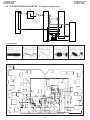
5-3-3-1. Adjusting the power
circuit
5-3-3. Adjusting the VCR circuit
• Test Points on the Video Circuit Board
a) POWER CIRCUIT ADJUSTMENT
PROCEDURE
Turn on power (camera).
û
1. Adjust to CAM 15V.
û
2. Check P-CON 4.9V.
û
3. Check P-CON 3.3V.
û
4. Check CAM 2.9V.
û
5. Check LCD 13.5V.
û
6. Check LCD 7V.
û
7. Check LCD -15.2V.
û
8. Check LCD -7V.
û
Æ Turn off power.
POWER CIRCUIT ADJUSTMENT METHOD
Æ Input 9V from DC Jack, and set the power switch to the camera side.
` Don't fail to fix the back light unit befor adjusting them.
1. Adjustment to CAM 15V
Make an adjustment so that the digital voltmeter indicates 15V
± 0.05V.
Measuring instrument
Digital voltmeter
Measuring terminal
TL905
Adjustment address
3EH
Standard
15V ± 0.05V
5. Checking of LCD 13.5V
Ascertain that the digital voltmeter indicates 13.5V ± 0.2V.
Measuring instrument
Digital voltmeter
Measuring terminal
TL907
Adjustment address
Standard
13.5V ± 0.2V
6. Checking of LCD 7V
Ascertain that the digital voltmeter indicates 7V +0.4/-0.2V.
2. Checking of P-CON 4.9V
Check that the digital voltmeter indicates 4.9V ± 0.1V.
Measuring instrument
Measuring terminal
Adjustment address
Standard
Measuring instrument
Measuring terminal
Adjustment address
Standard
Digital voltmeter
TL901
4.9V ± 0.1V
3. Checking of P-CON 3.3V
Ascertain that the digital voltmeter indicates 3.3V ± 0.1V.
Measuring instrument
Digital voltmeter
Measuring terminal
TL903
Adjustment address
Standard
3.3V ± 0.1V
4. Checking of CAM 2.9V
Ascertain that the digital voltmeter indicates 2.9V ± 0.1V.
Measuring instrument
Digital voltmeter
Measuring terminal
TL910
Adjustment address
Standard
2.9V ± 0.1V
Digital voltmeter
TL904
7V +0.4/-0.2V
7. Checking of LCD -15.2V
Ascertain that the digital voltmeter indicates -15.2V ± 1V.
Measuring instrument
Measuring terminal
Adjustment address
Standard
Digital voltmeter
TL906
-15.2V ± 1V
8. Checking of LCD -7V
Ascertain that the digital voltmeter indicates -7V +0.4/-0.7V.
Measuring instrument
Measuring terminal
Adjustment address
Standard
Æ Turn off power supply.
5-5
Digital voltmeter
TL908
-7V +0.4/-0.7V
VL-H870U
VL-H860S/H/VL-H870S
VL-H875U
VL-H890S/VL-H94E
VL-H890U
VL-H96E/VL-H960E
VL-H860S/H/VL-H870S
VL-H890S/VL-H94E
VL-H96E/VL-H960E
5-3-4. Adjustment of system controller and servo circuit
5-3-4-1. Adjustment of playback switching point
Measuring instrument Oscilloscope
b) CHARGING CIRCUIT ADJUSTMENT PROCEDURE
Mode
Playback
1) Play back the alignment tape (JiGWR5-5CSP)
2) Press the “CONTINUOUS PUSH” and “TEST MODE SELECAdjustment address 30h
TION” of adjustment remote controller to set the test mode.
Tape
Alignment tape (JiGWR5-5CSP)
(At this time the numeral of “TEST01” blinks.)
3) Using the “FF” and “REW” keys, select “TEST08”, and press the playback key to set the SW-P adjustment mode.
4) After a while the adjustment is completed, and operation stops automatically.
In case of adjustment failure the tape is ejected automatically.
Only in the case when the satisfactory result was not obtained by the adjusting method described above, perform the following
adjustment.
1) Connect each signal to the oscilloscope.
1ch: Video output ..... TL3402
2ch: H-SW-P ............ TL404
GND: GND ................. TL7449
2) Play back the alignment tape (JiGWR5-5CSP)
3) Press the “CONTINUOUS PUSH” and “VCR ADJUSTMENT” of adjustment remote controller to set the VCR adjustment mode.
4) Select the address 30h, set the sync slope of oscilloscope to (–),
6H
6H
adjust the data with “REW” and “FF” so that the interval between
3H
3H
3H
3H
the trigger point and the V sync signal is set to 6H, and fix the data
with the “PLAY” button. (See Figure 5.1.1.)
5) Then, set the sync slope to (+), and ascertain that the interval
V sync signal
V sync signal
between the trigger point and the V sync signal has been set to 6H.
(See Figure 5.1.2.)
6) Keep the STOP key pressed for about 3 seconds to exit from the
adjustment mode.
Figure 5.1.2
Figure 5.1.1
5-3-5. Y/C circuit adjustment method
White (approx. 100%)
Input signal conditions
Video signals generated by a pattern generator are used
to make electric adjustments in a Y/C circuit. Thus this
signal must conform to the standards prescribed for adjustment signals.
Use an oscilloscope to check that the video signal is
terminated with a 75 Ω resistor, the amplitude of the sync
signal component, video component and burst signal are
approx. 0.3 Vp-p, 0.7 Vp-p and 0.3 Vp-p, respectively and
that they are flat. The relative level of the burst signal and
the red signal shall be 0.30:0.66.
The color bar used in an electrical adjustment is shown in
Figure A.
Burst signal
Approx. 0.7 V p-p
Approx. 0.3 V p-p
Approx. 0.3 Vp-p
Red (approx. 0.6 V p-p)
Horizontal sync signal
Figure A Color bar signal produced by a pattern generator
* When a pattern generator is not used
Shoot a color bar chart (JiGCHART-4) using a perfectly
adjusted video camera.
A signal from a perfectly adjusted video camera shooting
a color bar chart (JiGCHART-4) can be used as an adjusting signal if the lighting can be set to meet the following
conditions: output (75 Ω terminated), the amplitude of the
sync signal component, video component and burst signal
are approx. 0.3 Vp-p, 0.7 Vp-p and 0.3 Vp-p, respectively.
The relative level of the burst signal and the red signal shall
be 0.30:0.66. This is shown in Figure B.
White (approx. 100%)
Burst signal
Approx. 0.7 V p-p
Approx. 0.3 V p-p
Approx. 0.3 V p-p
Red (approx. 0.6 V p-p )
Horizontal sync signal
Figure B Color bar signal produced by a video camera
1. Adjustment of fixed data writing
ADD
DATA
67
01
68
00
69
02
S·H
*6A
*00
E
*6A
*01
6B
C8
6C
00
6D
00
6E
66
6F
11
55
FE
5A
C0
66
FE
54
FE
65
FE
5C
C0
64
C0
Before starting Y/C adjustment, be sure to write the specific data in the addresses listed left.
If the data listed left is written after Y/C adjustment, adjusting values may deviate.
* As for S · H, after all conditioning (VCR circuit) is shut down, Data of 6A is changed in accordance with the above table.
5-6
VL-H870U
VL-H860S/H/VL-H870S
VL-H875U
VL-H890S/VL-H94E
VL-H890U
VL-H96E/VL-H960E
VL-H860S/H/VL-H870S
VL-H890S/VL-H94E
VL-H96E/VL-H960E
2. Adjustment of EE Y level
Measuring instrument Oscilloscope
Mode
VCR STOP
Input signal
Color bar
500 ± 20 mVp-p
Measuring point
TL3402, TL8356 (GND)
Adjustment address
32
Adjustment level
500 ± 20 mVp-p
(1) Input the color bar signal into the video input/output terminal in the VCR STOP mode.
(2) Enter the VCR adjustment mode with an adjustment remote control, and select the address 32.
Select the address, using the FF or REW key, and fix it with the PB key.
(3) Make an adjustment so as to get 500 mVp-p between SYNC TIP and WHITE PEAK on TL3402.
Select the data, using the FF or REW key, and fix it with the PB key.
After the adjustment, press the STOP key, and exit from the adjustment address 32.
3. Adjustment of comb filter
Minimum chroma component
Measuring instrument Oscilloscope
Mode
VCR STOP
Input signal
Color bar
Measuring point
TL414, TL8356 (GND)
Adjustment address
Phase: 36, Gain: 37
Adjustment level
Minimum chroma component
(1) Input the color bar signal into the video input/output terminal in the VCR STOP mode.
(2) Enter the VCR adjustment mode with an adjustment remote control, and select the address 36.
Select the address, using the FF or REW key, and fix it with the PB key.
(3) Make an adjustment so as to minimize the chroma component on TL414.
Select the data, using the FF or REW key, and fix it with the PB key.
After the adjustment, press the STOP key, and exit from the adjustment address 36.
(4) Enter the VCR adjustment mode with an adjustment remote control, and select the address 37.
Select the address, using the FF or REW key, and fix it with the PB key.
(5) Make an adjustment so as to minimize the chroma component on TL414.
Select the data, using the FF or REW key, and fix it with the PB key.
After the adjustment, press the STOP key, and exit from the adjustment address 37.
(6) Repeat the steps (2) - (3).
4. Adjustment of Y emphasis level
Measuring instrument Oscilloscope
Mode
VCR STOP
Input signal
Color bar
500 ± 20 mVp-p
Measuring point
TL408, TL8356(GND)
Adjustment address
56
Adjustment level
500 ± 20 mVp-p
(1) Input the color bar signal into the video input/output terminal in the VCR STOP mode.
(2) Enter the VCR adjustment mode with an adjustment remote control, and select the address 56.
Select the address, using the FF or REW key, and fix it with the PB key.
(3) Make an adjustment so as to get 500 mVp-p between SYNC TIP and WHITE PEAK on TL408.
Select the data, using the FF or REW key, and fix it with the PB key.
After the adjustment, press the STOP key, and exit from the adjustment address 56.
5. Adjustment of Y de-emphasis (Hi-8)
Measuring instrument Oscilloscope
Mode
PB
Input signal
Color bar (JiGWR5-8CSE)
500 ± 20 mVp-p
Measuring point
TL405, TL8356(GND)
Adjustment address
57
Adjustment level
500 ± 20 mVp-p
(1) Set the color bar tape for alignment (JiGWR5-8CSE).
(2) Enter the VCR adjustment mode with an adjustment remote control, and select the address 57.
Select the address, using the FF or REW key, and fix it with the PB key.
(3) Make an adjustment so as to get 500 mVp-p between SYNC TIP and WHITE PEAK on TL405
Select the data, using the FF or REW key, and fix it with the PB key.
After the adjustment, press the STOP key, and exit from the adjustment address 57.
6. Adjustment of Y de-emphasis (Normal-8)
Measuring instrument Oscilloscope
Mode
PB
Input signal
Color bar (JiGWR5-5CSP)
Measuring point
TL405, TL8356(GND)
500 ± 20 mVp-p
Adjustment address
62
Adjustment level
500 ± 20 mVp-p
(1) Set the color bar tape for alignment (JiGWR5-5CSP).
(2) Enter the VCR adjustment mode with an adjustment remote control, and select the address 62.
Select the address, using the FF or REW key, and fix it with the PB key.
(3) Make an adjustment so as to get 500 mVp-p between SYNC TIP and WHITE PEAK on TL405.
Select the data, using the FF or REW key, and fix it with the PB key.
After the adjustment, press the STOP key, and exit from the adjustment address 62.
5-7
VL-H870U
VL-H860S/H/VL-H870S
VL-H875U
VL-H890S/VL-H94E
VL-H890U
VL-H96E/VL-H960E
VL-H860S/H/VL-H870S
VL-H890S/VL-H94E
VL-H96E/VL-H960E
7. Adjustment of PB Y level
Measuring instrument Oscilloscope
Mode
PB
Input signal
Color bar (JiGWR5-8CSE)
500 ± 20 mVp-p
Measuring point
TL3402, TL8356(GND)
Adjustment address
3F
Adjustment level
500 ± 20 mVp-p
(1) Set the color bar tape for alignment (JiGWR5-8CSE).
(2) Enter the VCR adjustment mode with an adjustment remote control, and select the address 3F.
Select the address, using the FF or REW key, and fix it with the PB key.
(3) Make an adjustment so as to get 500 mVp-p between SYNC TIP and WHITE PEAK on TL3402.
Select the data, using the FF or REW key, and fix it with the PB key.
After the adjustment, press the STOP key, and exit from the adjustment address 3F.
8. Adjustment of chroma emphasis f0
Measuring instrument Oscilloscope
Minimum chroma component
Mode
VCR STOP
Input signal
Color bar
Measuring point
TL409, TL8356 (GND)
Adjustment address
38
Adjustment level
Minimum chroma component
(1) Input the color bar signal into the video input/output terminal in the VCR STOP mode.
(2) Enter the VCR adjustment mode with an adjustment remote control, and select the address 38.
Select the address, using the FF or REW key, and fix it with the PB key.
(3) Make an adjustment so as to get minimum chroma component on TL409.
Select the data, using the FF or REW key, and fix it with the PB key.
After the adjustment, press the STOP key, and exit from the adjustment address 38.
9. Adjustment of Y-FM carrier (Hi-8)
Measuring instrument Frequensy counter
Mode
VCR STOP
Input signal
No input
Measuring point
TL7443
Adjustment address
33
Adjustment level
5.99 ± 0.02kHz
(1) Input the no-signal into the video input/output terminal in the VCR
STOP mode.
At this time, do not pull out the jack on the Viewcam side.
(2) Enter the VCR adjustment mode with an adjustment remote
control, and select the address 33.
Select the address, using the FF or REW key, and fix it with the PB
key.
(3) Make an adjustment so that the frequency counter indicates
5.99MHz on TL7443.
Select the data, using the FF or REW key, and fix it with the PB key.
After the adjustment, press the STOP key, and exit from the
adjustment address 33.
10. Adjustment of Y-FM deviation (Hi-8)
Measuring instrument Oscilloscope
Mode
RWC/PB (self-playback/recording)
Input signal
Color bar
Measuring point
TL3402
500 ± 20 mVp-p
Adjustment address
34
Adjustment level
500 ± 20 mVp-p
(1) Set the recordable tape.
(2) Before entering the adjustment mode,make self-playback/recording of color bar with an external output.
Measure whether the playback output at this time is 500 mVp-p on TL3402 (Hi8 TAPE).
(3) Enter the VCR adjustment mode with an adjustment remote control, and select the address 34.
Select the address, using the FF or REW key, and fix it with the PB key.
(4) When decreasing by 10 mVp-p as compared to the measurement value of (2), decrease the data of address 34 by about 5 (digit).
(Reference)
When increasing by 10 mVp-p as compared to the measurement value of (2), increase the data of address 34 by about 5 (digit).
(Reference)
Select the address, using the FF or REW key, and fix it with the PB key.
(5) Release the adjustment mode, and make self-playback/recording again. When the measuring value at this time is in the standard
value, the adjustment is completed. If it is not in the standard value, repeat the steps (2) -(4).
(6) After completing the adjustment of (5), check the adjusting value of Y-FM carrier f0 (5.99 MHz in no input).
When the measuring value exceeds the standard value of carrier f0, make an adjustment of Y-FM carrier f0 again.
11. Adjustment of Y-FM carier f0 (Normal-8)
Measuring instrument Ferquensy counter
Mode
VCR STOP
Input signal
No input
Measuring point
TL7443
Adjustment address
60
Adjustment level
4.38 ± 0.02 MHz
(1) Input the no-signal into the video input/output terminal in the
VCR STOP mode.
At this time, do not pull out the jack on the Viewcam side.
(2) Enter the VCR adjustment mode with an adjustment remote
control, and select the address 60.
Select the address, using the FF or REW key, and fix it with the
PB key.
(3) Make an adjustment so that the frequency counter indicates
4.38 MHz on TL7443.
Select the data, using the FF or REW key, and fix it with the PB
key.
After the adjustment, press the STOP key, and exit from the
adjustment address 60.
5-8
VL-H870U
VL-H860S/H/VL-H870S
VL-H875U
VL-H890S/VL-H94E
VL-H890U
VL-H96E/VL-H960E
VL-H860S/H/VL-H870S
VL-H890S/VL-H94E
VL-H96E/VL-H960E
12. Adjustment of Y-FM deviation (Normal-8)
Measuring instrument Oscilloscope
Mode
REC/PB (self-playback/recording)
Input signal
Color bar
Measuring point
TL3402
Adjustment address
61
Adjustment level
500 ± 20 mVp-p
500 ± 20 mVp-p
(1) Set the recordable tape.
(2) Before entering the adjustment mode,make self-playback/recording of color bar with an external output.
Measure whether the playback output at this time is 500 mVp-p on TL3402 (Nor 8 TAPE).
(3) Enter the VCR adjustment mode with an adjustment remote control, and select the address 61.
Select the address, using the FF or REW key, and fix it with the PB key.
(4) When decreasing by 10 mVp-p as compared to the measurement value of (2), decrease the data of address 61 by about 5 (digit).
(Reference)
When increasing by 10 mVp-p as compared to the measurement value of (2), increase the data of address 61 by about 5 (digit).
(Reference)
Select the address, using the FF or REW key, and fix it with the PB key.
(5) Release the adjustment mode, and make self-playback/recording again. When the measuring value at this time is in the standard
value, the adjustment is completed. If it is not in the standard value, repeat the steps (2) -(4).
(6) After completing the adjustment of (5), check the adjusting value of Y-FM carrier f0 (4.38 MHz in no input).
When the measuring value exceeds the standard value of carrier f0, make an adjustment of Y-FM carrier f0 again.
13. Adjustment of REC-Y equalizer (Hi-8 ME)
SYNC
Measuring instrument Oscilloscope
(TL3402)
Mode
VCR STOP
Input signal
Color bar
Measuring point
TL7443
Adjustment address
58
530 mVp-p
Adjustment level
530 ± 20 mVp-p
(1) Input the color bar signal into the video input/output terminal in the VCR STOP mode.
(2) Enter the VCR adjustment mode with an adjustment remote control, and select the address 58.
Select the address, using the FF or REW key, and fix it with the PB key.
(3) Make an adjustment so that the SYNC TIP portion gets 530 mVp-p on TL7443.
Select the data, using the FF or REW key, and fix it with the PB key.
After the adjustment, press the STOP key, and exit from the adjustment address 58.
14. Adjustment of REC-Y equalizer (Hi-8 MP)
SYNC
Measuring instrument Oscilloscope
(TL3402)
Mode
VCR STOP
Input signal
Color bar
Measuring point
TL7443
Adjustment address
31
360 mVp-p
Adjustment level
360 ± 20 mVp-p
(1) Input the color bar signal into the video input/output terminal in the VCR STOP mode.
(2) Enter the VCR adjustment mode with an adjustment remote control, and select the address 31.
Select the address, using the FF or REW key, and fix it with the PB key.
(3) Make an adjustment so that the SYNC TIP portion gets 360 mVp-p on TL7443.
Select the data, using the FF or REW key, and fix it with the PB key.
After the adjustment, press the STOP key, and exit from the adjustment address 31.
15. Adjustment of REC-Y equalizer (Normal-8 ME)
SYNC
Measuring instrument Oscilloscope
(TL3402)
Mode
VCR STOP
Input signal
Color bar
Measuring point
TL7443
Adjustment address
63
510 mVp-p
Adjustment level
510 ± 20 mVp-p
(1) Input the color bar signal into the video input/output terminal in the VCR STOP mode.
(2) Enter the VCR adjustment mode with an adjustment remote control, and select the address 63.
Select the address, using the FF or REW key, and fix it with the PB key.
(3) Make an adjustment so that the SYNC TIP portion gets 510 mVp-p on TL7443.
Select the data, using the FF or REW key, and fix it with the PB key.
After the adjustment, press the STOP key, and exit from the adjustment address 63.
5-9
VL-H870U
VL-H860S/H/VL-H870S
VL-H875U
VL-H890S/VL-H94E
VL-H890U
VL-H96E/VL-H960E
VL-H860S/H/VL-H870S
VL-H890S/VL-H94E
VL-H96E/VL-H960E
16. Adjustment of REC-Y equalizer (Normal-8 MP)
SYNC
Measuring instrument Oscilloscope
(TL3402)
Mode
VCR STOP
Input signal
Color bar
Measuring point
TL7443
Adjustment address
3A
400 mVp-p
Adjustment level
400 ± 20 mVp-p
(1) Input the color bar signal into the video input/output terminal in the VCR STOP mode.
(2) Enter the VCR adjustment mode with an adjustment remote control, and select the address 3A.
Select the address, using the FF or REW key, and fix it with the PB key.
(3) Make an adjustment so taht the SYNC TIP portion gets 400 mVp-p on TL7443.
Select the data, using the FF or REW key, and fix it with the PB key.
After the adjustment, press the STOP key, and exit from the adjustment address 3A.
17. Adjustment of REC-C equalizer
Measuring instrument Oscilloscope
Mode
VCR STOP
Input signal
Color bar
Measuring point
TL7441
Adjustment address
59
Adjustment level
154 ± 10 mVp-p
Red part
154 mVp-p
(1) Input the color bar signal into the video input/output terminal in the VCR STOP mode.
(2) Enter the VCR adjustment mode with an adjustment remote control, and select the address 59.
Select the address, using the FF or REW key, and fix it with the PB key.
(3) Make an adjustment so taht the SYNC TIP portion gets 154 mVp-p on TL7441.
Select the data, using the FF or REW key, and fix it with the PB key.
After the adjustment, press the STOP key, and exit from the adjustment address 59.
18. Adjustment of Y recording current
Measuring instrument Oscilloscope
Mode
EE (VCR STOP)
Input signal (Tape)
Color bar
Test point
CH1; TL7410/TL7401 (GND)
CH2; TL7409/TL7401 (GND)
Adjustment address
105
Adjustment level
185 ± 10 mVp-p
SYNC
(TL3402)
185 mVp-p
(1) Connect TL7455 and TL 7453 with a proper short-jumper.
(2) Select the address105.
(3) Set the oscilloscope.
1 Connect the SIG side of oscilloscope CH1 probe to the TL7410, the GND side to the TL7401.
2 Connect the SIG side of oscilloscope CH2 probe to the TL7409, the GND side to the TL7401.
3 Using the oscilloscope, invert either CH1 or CH2 signal, and add two signals.
4 At this time match the CH1 and CH2 volts levels.
(4) Change the data value, and make an adjustment to get the specified value at SYNC position.
19. Adjustment of C recording current
Measuring instrument Oscilloscope
Mode
EE (VCR STOP)
Input signal (Tape)
Color bar
Test point
CH1; TL7410/TL7401 (GND)
CH2; TL7409/TL7401 (GND)
Adjustment address
104
Adjustment level
54 ± 2 mVp-p
Red part
54 mVp-p
(1) Connect TL7454 and TL 7453 with a proper short-jumper.
(2) Select the address104.
(3) Set the oscilloscope.
1 Connect the SIG side of oscilloscope CH1 probe to the TL7410, the GND side to the TL7401.
2 Connect the SIG side of oscilloscope CH2 probe to the TL7409, the GND side to the TL7401.
3 Using the oscilloscope, invert either CH1 or CH2 signal, and add two signals.
4 At this time match the CH1 and CH2 volts levels.
(4) Change the data value, and make an adjustment to get the specified value at Red position.
5-10
VL-H870U
VL-H860S/H/VL-H870S
VL-H875U
VL-H890S/VL-H94E
VL-H890U
VL-H96E/VL-H960E
VL-H860S/H/VL-H870S
VL-H890S/VL-H94E
VL-H96E/VL-H960E
5-3-6. Adjustment of audio circuit
Note: The data enclosed in the brackets [ ] are for the sub-channel.
1. Adjustment of filter f0
Measuring instrument Oscilloscope
Mode
Playback
Input signal
—
Measuring terminal
TL605
Adjustment address
VCR ADJ 05F
Set value
—
2. Playback level adjustment
Measuring instrument Voltage mater
Mode
Playback
Input signal
—
Measuring terminal
TL608 [TL607]
Adjustment address
VCR ADJ 05E [05D]
Set value
-7.5 dBs ±0.5 dB
(1) Connect the oscilloscope to TL605.
(2) Play back the stereo alignment tape (JiGWR5-9CS), and
adjust so that the waveform envelop of TL605 becomes as
smooth as possible. Before adjustment record the current
data of adjustment address 05F. Whenever the TELE. WIDE
key of adjustment remote controller is pressed, waveform
MAIN/SUB is switched. Select the point which gives the
flattest possible envelope.
(1) Before adjustment record the current data of adjustment
address 05E and 05D.
(2) Be sure to connect the voltage mater to TL608 [TL607].
(3) Play back the stereo alignment tape (JiGWR5-9CS), and
adjust so as to get an indication -7.5 dBs ±0.5 dB.
(4) Watching alternately TL608 and TL607, repeat adjustment of
05E and 05D.
(5) If data differs significantly from the first record value, this
implies adjustment failure.
5-3-7. Adjustment of LCD display circuit
Adjustment procedures and connections are the same as with the VCR section. (Refer to item 5-3-3)
1. LCD Data Setting
2. Inverter input Voltage Setting
VCR ADJ
VCR ADJ
Address
Data
Address
Data
4C
7A
10
D9
4D
B5
11
3 type
BD
4E
96
3.5 type
C6
4F
E5
12
3
type
99
50
64
3.5
type
A3
51
A9
52
96
53
E5
4B
20
3B
40
3. Contrast adjustment
Measuring point
TL1814 (G-OUT)
Address 40
Mode
VCR AV input
Adjusting method
1) Set the data of address 47 at the address 80.
2) Input white 100% as an AV input.
3) Connect TL1804 to GND. (The 1H inversion stops.)
4) Connect 220 KΩ between TL802 and GND.
5) Seeing the waveform of TL1814 (G-OUT), make an adjustment between the
white peak and the sync tip.
Adjustment standard 3.35V ± 0.1V
Remarks
———————
4. R-W/B adjustment
Measuring point
TL1814 (G-OUT) TL1813 (R-OUT)
Address 41
Mode
VCR AV input
Adjusting method
1) AV input: Nonsignal.
2) TL1814 (G-OUT): Oscilloscope CH1
TL1813 (R-OUT): Oscilloscope CH2
3) Adjust P-P of TL1813 becomes bigger 0.15V than TL1814.
Adjustment standard ±0.1Vp-p
Remarks
———————
5. B-W/B adjustment
Measuring point
TL1814 (G-OUT) TL1815(B-OUT)
Address 42
Mode
VCR AV input
Adjusting method
1) AV input: Nonsignal.
2) TL1814 (G-OUT): Oscilloscope CH1
3) TL1815 (B-OUT): Oscilloscope CH2
4) Adjust P-P of TL1815 become bigger 0.1V than TL1814.
Adjustment standard ±0.1Vp-p
Remarks
———————
5-11
V
G R
VL-H870U
VL-H860S/H/VL-H870S
VL-H875U
VL-H890S/VL-H94E
VL-H890U
VL-H96E/VL-H960E
VL-H860S/H/VL-H870S
VL-H890S/VL-H94E
VL-H96E/VL-H960E
6. VCO adjustment
Measuring point
Mode
Adjusting method
TL1802
Address 43
VCR AV input
1) AV input : NON Signal
2) Connect the frequency counter to TL1802, and adjust the frequency.
Adjustment standard 15.625kHz ± 100Hz
Remarks
———————
7. H-position adjustment
Measuring point
TL1802
Address 44
Mode
VCR AV input
Adjusting method
1) Input the white 100% signal as an AV input.
2) Connect the oscilloscope to TL1802, and adjust the pulse width.
t
V
Adjustment standard 3 type 3.3 ± 0.15µsec/3.5 type 3.8 ± 0.15µsec
Remarks
———————
8. COMMON PULSE adjustment
Measuring point
TL1818
Address 22
Mode
VCR AV input
Adjusting method
1) Set the data of address 47 at the address 80.
2) Input the white 100% signal as an AV input.
3) Connect the oscilloscope to TL1818, and adjust the pulse width.
Adjustment standard 6.6Vp-p ± 0.1Vp-p
Remarks
———————
9. Burst phase adjustment
Measuring point
TL1815
Address 49
Mode
VCR AV input
Adjusting method
1) Input the monochrome signal (R) to the AV input.
2) Connect TL1804 to GND. (1H inversion stop)
3) Set the data of address 48 to 30.
4) Minimize the signal level difference every 1H.
Same adjustment
1H
1H
Adjustment standard ±400mV
Remarks
———————
10. COM-BIAS adjustment
Measuring point
LCD panel display surface
Address 45
Mode
VCR AV input
Adjusting method
1) Input the white 40% signal as an AV input, and set data of address 47 at the address 80.
2) Set the illuminometer (TOPCON IM-3) on the LCD panel surface (do not allow entry of external light).
3) Connect the illuminometer to the oscilloscope.
4) Make an adjustment so as to minimize the ripple of output waveform.
Response time: 0.6 sec
5) Adjust again if longitudinal stripe appears evidently.
* Or set to the point where the black is settled deepest with the grey scale signal.
Adjustment standard Minimum
Remarks
Make an adjustment after aging for 5 minutes or more.
11. W/B adjustment
Measuring point
Mode
Adjusting method
LCD panel display surface
Address 41, 42
VCR AV input
1) White fade signal input.
2) Adjust so as to get the same white screen as that of standard monitor. (Adjust again, visually checking as
stated in item 5. 6.)
Adjustment standard Standard monitor
Remarks
Make an adjustment after aging for 5 minutes or more.
12. Touch panel position detection adjustment (VL-H870S/H890S/H96E/H960E)
Measuring point
LCD panel display area
Mode
VCR AV input
Adjusting method
1) Enter the adjustment of touch panel adjustment mode. (TEST mode OE)
+
1
2) Press successively the two-points OSD indication cross-shaped (+) one by one
1 the left above→ 2 the right below (setting point) → 34 (as you pleases).
+
2
Set back the adjustment mode by fifth touch (5).
Note: As touch the two-points indication (+), display the blue (12) → the purple
(34), the case color a light blue is the adjustment "OK" and the red is the adjustment "NG".
The touch (34) can check the adjustment with the tip of finger indiation.
5-12
VL-H870U
VL-H860S/H/VL-H870S
VL-H875U
VL-H890S/VL-H94E
VL-H890U
VL-H96E/VL-H960E
VL-H860S/H/VL-H870S
VL-H890S/VL-H94E
VL-H96E/VL-H960E
5-4. ADJUSTMENT OF CAMERA SECTION
5-4-1. Servicing of camera section
(1) Object, measuring instrument and jigs necessary for camera section servicing
•
•
•
•
•
Gray scale chart
Vectorscope
Extension cable
Oscilloscope
Video output cable
• Color bar chart
• Color temperature conversion filter
HOYA "LB-165"
• Digital voltmeter
•
•
•
•
Halogen light (2 pcs.)
Color video monitor
AC adapter
Service Remote Control
Configuration
<Note: The entries of list> 1. Name 2. Part No. 3. Code
1. Gray Scale Chart
(390 x 520 mm)
2. JiGCHART-1
3. CP
1. Color Bar Chart
(240 x 320 mm)
2. JiGCHART-4
3. DA
1. Color Temperature
Conversion Filter
2. JiGHOYA-LB165
3. BN
1. Service Remote Control
2. RRMCG0033TASA
3. BT
Note:
1. Color temperature conversion filter (jig item No.3) may be obtained from HOYA Optics in your local market.
2. N: Indicates the new jigs.
• Connections for Camera Section Servicing
LENS
CCD
PWB
19pin
20pin
SC6
SC2
SC3
18pin
19pin
SC4
Connected FPC between the camera
and the VCR.
5-4-2. Adjustment procedures
This adjusting procedure covers all the steps for conducting the adjustments all the way. There are some steps that may be skipped,
depending on the specific needs for servicing and adjustment.
1. Checking the power supply voltage
3. Adjusting the black balance and AF noise level
2. Adjusting the auto focus
* Preparation: Set the auto focus adjustment mode.
4. Adjusting the burst gain
5. Adjusting the white balance
3. Adjusting the camera signal
1. Adjusting the camera signal
* Preparation: Set the camera signal adjustment mode.
6. Adjusting the color gain
2. Adjusting the iris AE
7. Adjusting the out door white balance
5-13
VL-H870U
VL-H860S/H/VL-H870S
VL-H875U
VL-H890S/VL-H94E
VL-H890U
VL-H96E/VL-H960E
VL-H860S/H/VL-H870S
VL-H890S/VL-H94E
VL-H96E/VL-H960E
5-4-2-1. Checking the power supply voltage
• Measuring terminal: CAM 4.9V
CAM 2.8V
CAM 3.1V
CAM 15V
CAM -7V
LENS 5V
• Measuring instrument: Digital voltmeter
5-4-2-2. Auto focus adjustment
• Basic iris adjustment
Measuring instrument None
DATA
Adjustment
Subject
—
09
Hall offset
Tape
—
0A
Iris offset
Test point
None
0B
Iris close
Adjustment address
1FF
Adjustment level
09, 0A, 0B
1) Set up the auto focus adjustment mode. (Write 01 to the address 1FE)
2) Write the adjustment data 09, 0A and 0B one after the other to the address 1FF, the adjustment are as above.
• Lens adjustment
Measuring instrument
Subject
Tape
Test point
Adjustment address
Adjustment level
None
More than 50 m away
—
None
1FF
11, 12, 06, 08, 0D
DATA
11
12
06
08
0D
Adjustment
Voltage adjustment
Optical wide-end adjustment
Wide-end focus ∞ position adjustment
Tele-end focus ∞ position adjustment
Zoom tracking adjustment
1) Set up the auto focus adjustment mode.
(This is unnecessary after the above basic iris adjustment has been made.)
2) Write the adjustment data 11, 12, 06, 08 and 0D one after the other to the address 1FF. The adjustments are as above.
Write FF to the address 1FE to exit the auto focus adjustment mode.
5-4-2-3. Adjustment of Camera signal
• Before starting these adjustment, auto focus adjustment must be finished.
• Set up the camera signal adjustment mode (Write 00 to the address 1FE)
1. Sync level adjustment
Measuring instrument Oscilloscope
Subject
Anything
Tape
—
Test point
VIDEO OUT (Terminated in 75Ω)
Adjustment address
1F8
Adjustment level
300mVp-p
1) Connect the oscilloscope to the VIDEO-OUT. Adjust the sync
level to 300mVp-p.
Video
SYNC
300mVp-p
1H
2. Iris AE adjustment
Measuring instrument Oscilloscope
Subject
Gray scale
700mVp-p
Tape
—
Test point
VIDEO-OUT
Adjustment address
1FC
Adjustment level
700mVp-p
1) Shoot the gray scale in the standard way. Observe the VIDEO-OUT signal on the oscilloscope screen and rewrite the data of
address 1FC to get an amplitude of 700mVp-p as shown above.
3. Black balance , AF noise level adjustment
Measuring instrument None
Subject
Anything
Tape
—
Test point
None
Adjustment address
1FF
Adjustment level
01
1) Preparation : Write FF to address 19C, 19D, 19E, 19F, 1AO,
1AI.
2) Write the data 01 to the address 1FF.
The following adjustments are automatically
carried on ; 1 Black balance adjustment
2 AF noise level adjustment
at AGC Gain Min , AGC Gain Max and Gain up.
3) Data processing after adjusting the noise level calculation
formula (Round off fractions).
5-14
VL-H870U
VL-H860S/H/VL-H870S
VL-H875U
VL-H890S/VL-H94E
VL-H890U
VL-H96E/VL-H960E
VL-H860S/H/VL-H870S
VL-H890S/VL-H94E
VL-H96E/VL-H960E
4. Data processing after adjusting the black balance
1) 5 digit subtraction from ROB adjustment data at AGC MIN (address 19Ch) = (address 19ch) - 5h
5 digit subtraction from ROB adjustment data at AGC MAX (address 19Dh) = (address 19Dh) - 5h
5 digit subtraction from ROB adjustment data at GAIN UP (address 19Eh) = (address 19Eh) - 5h
5. Burst gain adjustment
Measuring instrument Oscilloscope
Subject
None
Tape
—
Test point
VIDEO OUT (Terminated in 75 Ω)
Adjustment address
1F9
Adjustment level
300mVp-p
1) Measure the burst signal level on the oscilloscope. Using the
address 1F9, adjust the burst amplitude to 300mVp-p.
6. White balance adjustment
Measuring instrument Vector scope
Subject
Gray scale
Tape
—
Test point
VIDEO OUT (Terminated in 75 Ω)
Adjustment address
R-W/B 010, B-W/B 012
Adjustment level
R-W/B 0 % ± 3 %
(E, EW, EX model)
B-W/B 0 % ± 3 %
(S, H model)
R-W/B 19 % ± 3 %
B-W/B -11 % ± 3 %
1) E, EW, EX model adjust the spot to the center of vector scope (RY : 0%, B-Y : 0%) using address 010 and 012.
S, H model adjust the spot to the point of vector scope (R-Y : 19%,
B-Y : -11% ratio to burst) using address 010 and 012.
300mVp-p
[S, H]
[E, EW, EX]
R-Y
R-Y
Spot
Spot
B-Y
B-Y
Center point
7. Color gain adjustment
Measuring instrument
Subject
Tape
Test point
Adjustment address
Vector scope
Color bar chart
—
VIDEO OUT (Terminated in 75 Ω)
R GAIN 0DD
B GAIN 0DB
R MAT 0D7
B MAT 0D9
Adjustment level
R GAIN; Burst ratio 1.2 ± 0.1
B GAIN; Burst ratio 1.0 ± 0.1
R MAT; 107 ± 2°
B MAT; 340 ± 2°
1) Using the address 0DD, adjust the R level to a burst ratio of 1.2.
With the address 0DB, adjust the B level to a burst ratio of 1.0.
2) Using the address 0D7, adjust the R phase to 107°. With the
address 0D9, adjust the B phase to 340°.
3) Repeat the above steps 1) and 2).
R-Y
R spot
R level
340°
107°
B-Y
Burst
B spot
B level
R-Y
8. Out door white balance adjustment
Measuring instrument Vector scope
Spot
Subject
Gray scale
Tape
—
Test point
VIDEO OUT (Terminated in 75 Ω)
B-Y
Adjustment address
R-OUT DOOR 016
B-OUT DOOR 018
Adjustment level
R-OUT DOOR; 0 ± 3 %
Center point
B-OUT DOOR; 0 ± 3 %
1) Attach the color temperature conversion filter (JiGHOYA-LB165) to the front of the lens.
2) Using the addresses R-OUT DOOR 016 and B-OUT DOOR 018, adjust the spot to the center.
3) Take off the color temperature conversion filter.
When you have finished, write FF to the adress 1FE to exit camera signal
adjustment mode.
5-15
VL-H870U
VL-H860S/H/VL-H870S
VL-H875U
VL-H890S/VL-H94E
VL-H890U
VL-H96E/VL-H960E
VL-H860S/H/VL-H870S
VL-H890S/VL-H94E
VL-H96E/VL-H960E
5-5. TROUBLE SHOOTING
5-5-1. Classification of troubles
No function at all
Check the Power circuit and system control circuit.
û YES
Check the system control and loading motor circuit.
û YES
Check the inverter transformer and power circuit.
û YES
* Check the camera section and Y/C circuit and LCD
circuit.
û YES
Check the Y/C circuit and head amplifier circuit.
û YES
Check the Y/C circuit and head amplifier circuit.
û YES
Check the Y/C circuit and head amplifier circuit.
û YES
Check the ATF circuit.
û YES
Check the LCD circuit and character generator (IC705).
û YES
* Check the camera section and Y/C circuit.
û YES
Check the Y/C circuit and head amplifier circuit.
û YES
Check the Y/C circuit and head amplifier circuit.
û YES
Check the audio circuit.
û YES
Check the system controller and CAP MOTOR DRIVER
circuit.
û
û YES
No tape ejection
û
No LCD light-up
û
No picture in EE mode
û
No picture playback
û
No video recording
û
Streaking at self-recording/playback
Black streaking
û
Noises at regular intervals in playback
û
No recorded characters on screen
û
No color in EE mode
û
No color in playback
û
No color in recording
û
No sound
û
Error message (e.g. E007)
û
Normal
5-16
VL-H870U
VL-H860S/H/VL-H870S
VL-H875U
VL-H890S/VL-H94E
VL-H890U
VL-H96E/VL-H960E
VL-H860S/H/VL-H870S
VL-H890S/VL-H94E
VL-H96E/VL-H960E
5-5-2. Troubleshooting for the camera section
No picture
Check the lens drive circuit (IC551) and main signal
line.
û YES
Check IC201 (DSP), and their peripherals.
û YES
Check IC501 (camera CPU) and its peripherals.
û YES
Check IC501, IC551 and their peripherals.
û YES
Check IC501, IC551 and their peripherals.
û
û YES
No color
û
No auto white balance function
û
No auto focus function
û
No power zoom function
û
Normal
5-5-3. Charging mode troubles
Start
Is ADP-DET "H"? *1
"H"
Check the circuit of SYSCON.
"L"
Is CHG-ON "L" or "H"? *2
"H"
Check the circuit of SYSCON.
"L"
Is BAT DET "OV" ?
YES
Check Q2911, R2927, R2928, R2914, R2915
and battery terminal unit.
NO
Is BAT DET CK voltage more
than 4V or less than 8.4V.
NO
Battery is defective.
YES
Is the output voltage of Q2901,
1pin more than 9V.
NO
Check the AC adapter.
YES
Is Q2905 collect voltage
indicating.
Check Q2905, IC2901 and around the circuits.
less than 4V
more than 4V
Check the D2904, R2906,
R2933, R2921~R2923 and
CP901.
*1: Inputting DC power and set the ADP DET "L".
*2: Inputting charging mode as CHG ON "L".
5-17
VL-H870U
VL-H860S/H/VL-H870S
VL-H875U
VL-H890S/VL-H94E
VL-H890U
VL-H96E/VL-H960E
VL-H860S/H/VL-H870S
VL-H890S/VL-H94E
VL-H96E/VL-H960E
6. SYSTEM BLOCK DIAGRAMS
BATTERY
NONREGE
IC701 & Q701
IC900
POWER (CAMERA)
3.3V
Converter
POWER (SYS 3.3V)
POWER (AT 3.3V)
IC704
DC/DC
CONVERTOR
IC501
CAMERA
MICROCOMPUTER
SYSTEM SERVO
CONTROLLER
KEY
SERIAL BUS
IC703
IC2
E2PROM
2
E PROM
IC4701 & IC4702
D/A
SERIAL BUS
POWER (MOTOR)
POWER (SIGNAL)
Y/C
IC401
AUDIO
IC601
ATF
SERVO
CIRCUIT
IC2702
IC800
H/A
UNIT
MECHACHASSIS
LCD
CIRCUIT
MECHANISM
* On this model, all the circuits of the VCR and camera sections are controlled by IC704 and IC501.
1) IC501 and IC401 are controlled with the serial data from IC704.
2) IC703 is a memory that serves to store the adjustment data of the VCR section.
3) IC2 is a memory that serves to store the adjustment data of the camera section.
4) The other circuits and ICs are under the L/H level or the PWM control.
6-1
VL-H860S/H/VL-H870S
VL-H890S/VL-H94E
VL-H96E/VL-H960E
VL-H860S/H/VL-H870S
VL-H890S/VL-H94E
VL-H96E/VL-H960E
6-1. CAMERA SECTION BLOCK DIAGRAM
SC902
IC1401
IC401
IC7451
CN7401
2
39
22
26
49
1
3
58
4
24
20
24
41
7
5
61
14
18
13
12
17
15
Signal waveform
(2), (6), (7), (8), (9)
(10), (11)
(1), (3)
(4), (5)
Y SIGNAL :
C SIGNAL :
YC SIGNAL :
SC902
(2)
4
(1)
(4)
(9)
49
IC401
41
13
15
(3)
17
18
24
26
(5)
(6)
CN7401
58
24
22 20
61
39
(7)
14
12
3
IC7451
5
(10)
1
(11)
IC1401
(8)
7
6-2
2
VL-H870U
VL-H860S/H/VL-H870S
VL-H875U
VL-H890S/VL-H94E
VL-H890U
VL-H96E/VL-H960E
VL-H860S/H/VL-H870S
VL-H890S/VL-H94E
VL-H96E/VL-H960E
6-2. VCR SECTION BLOCK DIAGRAM Y/C playback signal frow
CN7401
IC8301
IC401
IC1401
8
10
13
1
43
2
8
3
18
14
17
12
15
SC601
13
6
47
34
43
36
48
20
10
26
22
52
60
51
4
41
2
51
15
38
45
2
50
IC2401
7
Signal waveform
(1), (2), (9)
(3)
(4), (5), (6), (7)
(10), (11), (12), (13), (14) (8)
Y SIGNAL :
C SIGNAL :
YC SIGNAL :
(14)
(6)
(3)
51
52
8
38
36
34
13
(13)
15
(2)
IC401
47
43
3
17 18 20
26
IC2401 15
(8)
IC8301
1
CN7401
2
(11)
2
22
13
(1)
14
IC1401
(5)
12
41
43
45
48
10
8
10
(12)
50
51
(10)
(4)
60
(7)
6
SC601
2
(9)
6-3
4
7
VL-H860S/H/VL-H870S
VL-H890S/VL-H94E
VL-H96E/VL-H960E
VL-H860S/H/VL-H870S
VL-H890S/VL-H94E
VL-H96E/VL-H960E
6-3. VCR SECTION BLOCK DIAGRAM Y/C EE signal frow
IC1401
IC800
58
5
56
3
CN1800
19
9
21
10
24
11
IC401
45
SC902
4
48
36
43
34
4
24
20
24
2
39
22
26
60
52
51
51
38
7
SC601
50
41
2
Signal waveform
(2), (7), (8), (9), (10), (12) (1), (3), (4), (5), (11), (13) (6)
(16)
(15)
(14)
Y SIGNAL :
C SIGNAL :
YC SIGNAL :
SC902
(2)
4
5
2
3
19
21
24
IC800
(1)
CN1800
(16)
11
10
(4)
9
(14)
52
(6)
51
IC401
38
36
(3)
34
(7)
24
24
22 20
26
(10)
(11)
IC1401
39
41
43
45
48
(8)
50 51 56 58 60
SC601
(5)
(12)
2
(13)
(9)
6-4
4
7
(15)
VL-H870U
VL-H860S/H/VL-H870S
VL-H875U
VL-H890S/VL-H94E
VL-H890U
VL-H96E/VL-H960E
VL-H860S/H/VL-H870S
VL-H890S/VL-H94E
VL-H96E/VL-H960E
6-4. AUDIO BLOCK DIAGRAM
MIX
DL
25
24
IC6601
LA7471M
25
INT
27
AMP
EQ
20
EQ
8
30
EXT
SC601
INT
1
AMP
34
EXT
3
4
5
DL
MIX
EXT-MiC_L_IN
18
EXT-MiC_R_IN
17
AUDIO GND
16
AUDIO-R in/out
11
AUDIO GND
10
AUDIO-L in/out
9
INT MIC
RMiCC0086TA
P6601
INT MIC R
3
MIC GND
2
INT MIC L
1
SPEAKER
VSP0028-50WN
P201
IC1602 BA7785FS
2
4
AMP
6
AMP
SP
(-)
19
13
SP
(-)
18
SP
(+)
17
SP
(+)
16
44 43
LEVEL
SENSOR
PB
CCA
LIMITER
5
DC
SHIFT
50
B
REC
OUTPUT
SWITCHING
1
SW
REC
2
LPF
PB
A
NR
PB
DC
SHIFT
52
VCO
MONO
MULTI
DET
1.5MHz
PLL
PB
IC602
TC4W66U
MUTE
MATRIX
REC AFM
BPF MONI
22
PB RF
20
PB MONO L
1.7MHz BPF
62
REC
LIMITER
AUDIO
LPF
MIC
AGC
MIX
STEREO ST MONO
ON
LPF
PB
LINE
PB
B
REC
REC
VCO
PB
DET
SW
A
NR
PB
MIC
FADE
23
PLAYBACK
FR AGC
BPF
FADE
24
MUTE DETECTION
CIRCUIT
1.5MHz BPF
REC
64
H.SW-P
DOD DETECTION
LIMITER CIRCUIT
REC
PB
31
LPF
AUDIO
LPF
REC
REC
LPF
AGC
LINE
LIMITER
CCA
DET
2
3
4
6
7
8
9
AFADE
6-5
LEVEL
SENSOR
PB
2
14
IC601
CXA1737R
6
1
(+)
SC902
AMP
46 45
(-)
SP
AMP
7
MUTE
SP
1.5MHz
PLL
Q307
6-6
5
SC305
67 D.O. PULSE
SC305
4 ROT ERASE
7
9
8 AGC IN
SC305
SC305
10 PB Y FM
30
58 REC-C
2
4
3
11
32
Q315
Q315
BUF
SC305
61 REC-Y
SC305
64 H-SW-P
SC305
65 OVER-P
SC305
6 PB RF
63 AV REC-H
SC305
PB
REC
VGC
VCC
DOC
9
AGC
Y
AMP
FF30
28
27
13
RECORDING
AMPLIFIER
CH-1
IC 301
REC/PB AMP IC
a
14
RECORDING
AMPLIFIER
CH-1
PLAYBACK
AMPLIFIER
CH-2
PLAYBACK
AMPLIFIER
CH-2
a
R339
Q302
BUF
ERASING
OSCILLATOR
ERASING OSCILLATOR
SWITCH CH-2
17
24
18
23
SC305
35
1
SC301
FE (F)
2
FE (S)
SC301
SC301
L (S) (REC) 5
SC301
R (S) (REC) 9
SC301
L (F) (PB) 6
SC301
R (F) (PB) 8
HOT
VIDEO HEAD
L
(CH-2)
VIDEO HEAD
R
(CH-1)
Hi8MP 40mVp-p
Hi8ME 40mVp-p
(11) TL35 (Pin (35) of P1)
ROTALY
ERASING
HEAD
ROTALYTRANSFORMER
(10) (11)
Hi8MP 130mVp-p
Hi8ME 190mVp-p
(10) TL35 (Pin (35) of P1)
Signal waveform
VL-H860S/H/VL-H870S
VL-H890S/VL-H94E
VL-H96E/VL-H960E
VL-H860S/H/VL-H870S
VL-H890S/VL-H94E
VL-H96E/VL-H960E
6-5. HEAD AMP BLOCK DIAGRAM
VL-H870U
VL-H860S/H/VL-H870S
VL-H875U
VL-H890S/VL-H94E
VL-H890U
VL-H96E/VL-H960E
VL-H860S/H/VL-H870S
VL-H890S/VL-H94E
VL-H96E/VL-H960E
6-6. POWER SYSTEM BLOCK DIAGRAM
Lithium ion 2 cell
P-CON 4.9V
Power control IC (VHiMB3825,6·CH)
1
CH1 ERROR AMP.
IN- Comparator section
IN+
1
4.9V Power
Valtage drop circuit
(PNP Tr)
CH1 output
Drive circuit
(Voltage drop)
CAM 4.9V
P-CON 3.3V
2
2
3
CH2 ERROR AMP.
IN- Comparator section
IN+
CH3 ERROR AMP.
IN- Comparator section
IN+
3.3V Power
Valtage drop circuit
(PNP Tr)
CH2 output
Drive circuit
(Voltage drop)
CAM 3.3V
3
LCD 13.2V
LCD 7V
LCD -7V
LCD -15V
Trans circuit
(NPN)
CH3 output
Drive circuit
(Voltage drop)
YC-7V
CAM 15V
CQAM-7V
4
4
CH4 ERROR AMP.
IN- Comparator section
IN+
CH4 output
Drive circuit
CAM 2.8V
Valtage drop circuit
(PNP Tr)
CH5 output
Drive circuit
(Voltage drop)
DRUM VS
Valtage drop circuit
(PNP Tr)
CAM 2.8V
5
5
CH5 ERROR AMP.
IN- Comparator section
IN+
DRUM
ERROR
6
CAP
ERROR
DRUM
DRIVER
6
CH6 ERROR AMP.
IN- Comparator section
IN+
CH6 output
Drive circuit
(Voltage drop)
CAP VS
Valtage drop circuit
(PNP Tr)
CAP
DRIVER
Standard
power
TRIANGLE
WAVE
OSC
Standard
power
7
CH1 ERROR AMP.
IN- Comparator section
IN+
7
Mecha 5V Power
Voltage drop circuit
(PNP Tr)
CH1 output
Drive circuit
(PNP)
MACHA5V/SP5V
LENS 5V
8
8
B/L CTL
CH2 ERROR AMP.
IN= Comparator section
IN+
B/L POW
Voltage drop circuit
(PNP Tr)
CH2 output
Drive circuit
(PNP)
6-7
BACK
LIGHT
INV
6-8
Charging : Red light up
Completion : Green light up
LED Green
DC JACK input
LED Red
LED_G
LED_R
with JACK : OPEN
with out JACK : GND Short circuit
VDC<11V
Voltage detective
circuit
Q2901
Current
detective
section
Charge control IC
Current control
circuit section
Vcc
ADP-DET
RESET
CHG SW
Voltage
detective
section
Q2903
NON REG 7.2V
CHARGE-ON_L
When the battery
is installed , its
turned "ON".
Lithium
ion battery
BATT.-DET
Q2903 with FET always is "OFF" at DC input.
Vcc
VCR-H
DC input lived
System microcomputer
VBATT=0
Charging off
Battery voltage
detection
DC input "ON"
"OFF" detection
SYS 3.3V
REG circuit
VL-H860S/H/VL-H870S
VL-H890S/VL-H94E
VL-H96E/VL-H960E
VL-H860S/H/VL-H870S
VL-H890S/VL-H94E
VL-H96E/VL-H960E
6-7. MAIN BATTERY CIRCUIT SECTION BLOCK DIAGRAM
VL-H870U
VL-H860S/H/VL-H870S
VL-H875U
VL-H890S/VL-H94E
VL-H890U
VL-H96E/VL-H960E
VL-H860S/H/VL-H870S
VL-H890S/VL-H94E
VL-H96E/VL-H960E
6-8. CAMERA SECTION BLOCK DIAGRAM
79
80
DATA/ADRS 28
CK
R/W
39
CS
MODE
43
DIS
N
SYS TO CAM
IC501
Camera µ-CON
Lens
IC151 1
A/D
~
5
8
39
18
20
22 12
øV
øH
11
~
17
~
IC101
21 CDS
4
22 AGC
IC1
CCD 14
SENSER
21
CAM TO SYS
100 ~ 110 112
XPADDA
R/W
MODE
A/DIN CK
CS
IC201
DSP
CAM-Y
45
VCR
LCD
PWB
CAM-C
38
MCKI
30
A/DCLK
IC11
V-DRIVER
H
V
IC12
TG 27
33
FSX
32
FCX
6-9. LENS DRIVE BLOCK DIAGRAM
IC1
CCD SENSER
MASTER LENS
IC501
100
28 DATA
107
35
IRIS CONTROL
61
1
2 23 61
13
14
15
12
4
ZOOM CONTROL
20
ZD ZD ZD ZM
1 CLK 3 CE
FD FD FM FM
4
1 CTL CE
(
(
(
(
(
(
FD
3
M
17 16 15
(HALL OFFSET)
OP-AMP
(DRIVE (+))
7
3
6
(IRIS OFFSET) 2
IC552
H
14
(HALL IN (–))
13
) 19
(IRIS H
) 18
3
OP-AMP
(HALL IN (+))
(IRIS L
IC502
D/A
8
Device
IC551
(FO2-)
FOCUS
MOTOR
M
LENS DRIVER
55
(FO2+)
54
(FO1+)
52
(FO1-)
51
FOCUS MOTOR
DRIVE
2
(FD1)
5
(FD4)
4
(FD3)
3
(FD2)
1
(FM CTL)
46
(FMCE)
ZOOM
LENS
POSI
(PHIRZ)
ZOOM
MOTOR
M
(ZO1+)
16
(ZO1-)
17
(ZO2+)
19
(ZO2-)
20
ZOOM MOTOR
DRIVE
13
(ZD1)
11
(ZD3)
9
(ZDCLK)
25
(ZMCE)
6-9
(
FD
2
(
IC553
4.9V
16 5 18 21
(
IRIS
METER
60
(
(PHIRF)
FOCUS CONTROL
(
(
(
(
(
(
Master
Lens
POSI
Camera µ-CON
(
IC201
DSP
(
IC151
A/D
(
IC101
CDS
AGC
(
ZOOM LENS
VL-H860S/H/VL-H870S
VL-H890S/VL-H94E
VL-H96E/VL-H960E
7-1
J
K
L
M
N
O
P
(1/4)
Q
R
S
LOCATION MAP:
1 3
2 4
7. SCHEMATIC DIAGRAMS 7-1. OVERALL SCHEMATIC DIAGRAM (VL-H860S/H/H94E)
LOCATION MAP:
1 3
2 4
VL-H860S/H/VL-H870S
VL-H890S/VL-H94E
VL-H96E/VL-H960E
(2/4)
10
9
8
7
6
5
4
3
2
7-2
A
B
C
D
E
F
G
H
I
J
1
7-3
J
K
L
M
N
O
P
(3/4)
Q
R
S
LOCATION MAP:
1 3
2 4
VL-H860S/H/VL-H870S
VL-H890S/VL-H94E
VL-H96E/VL-H960E
LOCATION MAP:
1 3
2 4
VL-H860S/H/VL-H870S
VL-H890S/VL-H94E
VL-H96E/VL-H960E
(4/4)
19
18
17
16
15
14
13
12
11
7-4
A
B
C
D
E
F
G
H
I
J
10
VL-H860S/H/VL-H870S
VL-H890S/VL-H94E
VL-H96E/VL-H960E
7-5
J
K
L
M
N
O
P
(1/4)
Q
R
S
LOCATION MAP:
1 3
2 4
7-1. OVERALL SCHEMATIC DIAGRAM (VL-H870S/H890S/H96E/H960E)
LOCATION MAP:
1 3
2 4
VL-H860S/H/VL-H870S
VL-H890S/VL-H94E
VL-H96E/VL-H960E
(2/4)
10
9
8
7
6
5
4
3
2
7-6
A
B
C
D
E
F
G
H
I
J
1
7-7
J
K
L
M
N
O
P
(VL-H890S/H960E)
(VL-H870S/H96E)
(VL-H890S/H960E)
(VL-H870S/H96E)
1 3
2 4
LOCATION MAP:
Q
R
S
VL-H860S/H/VL-H870S
VL-H890S/VL-H94E
VL-H96E/VL-H960E
(3/4)
(VL-H890S/H960E)
(VL-H870S/H96E)
LOCATION MAP:
1 3
2 4
VL-H860S/H/VL-H870S
VL-H890S/VL-H94E
VL-H96E/VL-H960E
(4/4)
19
18
17
16
15
14
13
12
11
7-8
A
B
C
D
E
F
G
H
I
J
10
VL-H860S/H/VL-H870S
VL-H890S/VL-H94E
VL-H96E/VL-H960E
7-9
J
K
L
M
N
O
P
(1/4)
Q
R
S
LOCATION MAP:
1 3
2 4
7-2. AUDIO CIRCUIT SCHEMATIC DIAGRAM
LOCATION MAP:
1 3
2 4
VL-H860S/H/VL-H870S
VL-H890S/VL-H94E
VL-H96E/VL-H960E
(2/4)
10
9
8
7
6
5
4
3
2
7-10
A
B
C
D
E
F
G
H
I
J
1
7-11
J
K
L
M
N
O
P
(3/4)
Q
R
S
LOCATION MAP:
1 3
2 4
VL-H860S/H/VL-H870S
VL-H890S/VL-H94E
VL-H96E/VL-H960E
LOCATION MAP:
1 3
2 4
VL-H860S/H/VL-H870S
VL-H890S/VL-H94E
VL-H96E/VL-H960E
(4/4)
19
18
17
16
15
14
13
12
11
7-12
A
B
C
D
E
F
G
H
I
J
10
VL-H860S/H/VL-H870S
VL-H890S/VL-H94E
VL-H96E/VL-H960E
7-13
J
K
L
M
N
O
P
(1/4)
Q
R
S
LOCATION MAP:
1 3
2 4
7-3. LCD CIRCUIT SCHEMATIC DIAGRAM (VL-H860S/H/H94E)
LOCATION MAP:
1 3
2 4
VL-H860S/H/VL-H870S
VL-H890S/VL-H94E
VL-H96E/VL-H960E
(2/4)
10
9
8
7
6
5
4
3
2
7-14
A
B
C
D
E
F
G
H
I
J
1
7-15
J
K
L
M
N
O
P
(3/4)
Q
R
S
LOCATION MAP:
1 3
2 4
VL-H860S/H/VL-H870S
VL-H890S/VL-H94E
VL-H96E/VL-H960E
LOCATION MAP:
1 3
2 4
VL-H860S/H/VL-H870S
VL-H890S/VL-H94E
VL-H96E/VL-H960E
(4/4)
19
18
17
16
15
14
13
12
11
7-16
A
B
C
D
E
F
G
H
I
J
10
VL-H860S/H/VL-H870S
VL-H890S/VL-H94E
VL-H96E/VL-H960E
7-17
J
K
L
M
N
O
P
(1/4)
Q
R
S
LOCATION MAP:
1 3
2 4
7-3. LCD CIRCUIT SCHEMATIC DIAGRAM (VL-H870S/H96E)
LOCATION MAP:
1 3
2 4
VL-H860S/H/VL-H870S
VL-H890S/VL-H94E
VL-H96E/VL-H960E
(2/4)
10
9
8
7
6
5
4
3
2
7-18
A
B
C
D
E
F
G
H
I
J
1
7-19
J
K
L
M
N
O
P
(3/4)
Q
R
S
LOCATION MAP:
1 3
2 4
VL-H860S/H/VL-H870S
VL-H890S/VL-H94E
VL-H96E/VL-H960E
LOCATION MAP:
1 3
2 4
VL-H860S/H/VL-H870S
VL-H890S/VL-H94E
VL-H96E/VL-H960E
(4/4)
19
18
17
16
15
14
13
12
11
7-20
A
B
C
D
E
F
G
H
I
J
10
VL-H860S/H/VL-H870S
VL-H890S/VL-H94E
VL-H96E/VL-H960E
7-21
J
K
L
M
N
O
P
(1/4)
Q
R
S
LOCATION MAP:
1 3
2 4
7-3. LCD CIRCUIT SCHEMATIC DIAGRAM (VL-H890S/H960E)
LOCATION MAP:
1 3
2 4
VL-H860S/H/VL-H870S
VL-H890S/VL-H94E
VL-H96E/VL-H960E
(2/4)
10
9
8
7
6
5
4
3
2
7-22
A
B
C
D
E
F
G
H
I
J
1
7-23
J
K
L
M
N
O
P
(3/4)
Q
R
S
LOCATION MAP:
1 3
2 4
VL-H860S/H/VL-H870S
VL-H890S/VL-H94E
VL-H96E/VL-H960E
LOCATION MAP:
1 3
2 4
VL-H860S/H/VL-H870S
VL-H890S/VL-H94E
VL-H96E/VL-H960E
(4/4)
19
18
17
16
15
14
13
12
11
7-24
A
B
C
D
E
F
G
H
I
J
10
VL-H860S/H/VL-H870S
VL-H890S/VL-H94E
VL-H96E/VL-H960E
7-4. CHARGE CIRCUIT SCHEMATIC DIAGRAM
J
I
H
G
F
E
D
C
B
A
1
2
3
4
5
6
7-25
7
8
9
10
VL-H860S/H/VL-H870S
VL-H890S/VL-H94E
VL-H96E/VL-H960E
å AND SHADED COMPONENTS=SAFETY RELATED PARTS
å
å
å
10
11
12
13
14
15
7-26
16
17
18
19
VL-H860S/H/VL-H870S
VL-H890S/VL-H94E
VL-H96E/VL-H960E
7-27
J
K
L
M
N
O
P
(1/4)
Q
R
S
LOCATION MAP:
1 3
2 4
7-5. YCPROCESS CIRCUIT SCHEMATIC DIAGRAM
LOCATION MAP:
1 3
2 4
VL-H860S/H/VL-H870S
VL-H890S/VL-H94E
VL-H96E/VL-H960E
(2/4)
10
9
8
7
6
5
4
3
2
7-28
A
B
C
D
E
F
G
H
I
J
1
7-29
J
K
L
M
N
O
P
(3/4)
Q
R
S
LOCATION MAP:
1 3
2 4
VL-H860S/H/VL-H870S
VL-H890S/VL-H94E
VL-H96E/VL-H960E
LOCATION MAP:
1 3
2 4
VL-H860S/H/VL-H870S
VL-H890S/VL-H94E
VL-H96E/VL-H960E
(4/4)
19
18
17
16
15
14
13
12
11
7-30
A
B
C
D
E
F
G
H
I
J
10
VL-H860S/H/VL-H870S
VL-H890S/VL-H94E
VL-H96E/VL-H960E
7-6. YCCCD DELAY CIRCUIT SCHEMATIC DIAGRAM
J
I
H
G
F
E
D
C
B
A
1
2
3
4
5
6
7-31
7
8
9
10
VL-H860S/H/VL-H870S
VL-H890S/VL-H94E
VL-H96E/VL-H960E
10
11
12
13
14
15
7-32
16
17
18
19
VL-H860S/H/VL-H870S
VL-H890S/VL-H94E
VL-H96E/VL-H960E
7-33
J
K
L
M
N
O
P
(1/4)
Q
R
S
LOCATION MAP:
1 3
2 4
7-7. YCRF CIRCUIT SCHEMATIC DIAGRAM
LOCATION MAP:
1 3
2 4
VL-H860S/H/VL-H870S
VL-H890S/VL-H94E
VL-H96E/VL-H960E
(2/4)
10
9
8
7
6
5
4
3
2
7-34
A
B
C
D
E
F
G
H
I
J
1
7-35
J
K
L
M
N
O
P
(3/4)
Q
R
S
LOCATION MAP:
1 3
2 4
VL-H860S/H/VL-H870S
VL-H890S/VL-H94E
VL-H96E/VL-H960E
LOCATION MAP:
1 3
2 4
VL-H860S/H/VL-H870S
VL-H890S/VL-H94E
VL-H96E/VL-H960E
(4/4)
19
18
17
16
15
14
13
12
11
7-36
A
B
C
D
E
F
G
H
I
J
10
VL-H860S/H/VL-H870S
VL-H890S/VL-H94E
VL-H96E/VL-H960E
å AND SHADED COMPONENTS=SAFETY RELATED PARTS
(1/4)
7-37
J
K
L
M
N
O
P
Q
R
S
å
LOCATION MAP:
1 3
2 4
7-8. POWER CIRCUIT SCHEMATIC DIAGRAM
LOCATION MAP:
1 3
2 4
VL-H860S/H/VL-H870S
VL-H890S/VL-H94E
VL-H96E/VL-H960E
(2/4)
å
10
9
8
7
6
5
4
3
2
7-38
A
B
C
D
E
F
G
H
I
J
1
7-39
J
K
L
M
N
O
P
(3/4)
Q
R
S
LOCATION MAP:
1 3
2 4
VL-H860S/H/VL-H870S
VL-H890S/VL-H94E
VL-H96E/VL-H960E
LOCATION MAP:
1 3
2 4
VL-H860S/H/VL-H870S
VL-H890S/VL-H94E
VL-H96E/VL-H960E
(4/4)
19
18
17
16
15
14
13
12
11
7-40
A
B
C
D
E
F
G
H
I
J
10
VL-H860S/H/VL-H870S
VL-H890S/VL-H94E
VL-H96E/VL-H960E
7-9. SERVO CIRCUIT SCHEMATIC DIAGRAM
J
I
H
G
F
E
D
C
B
A
1
2
3
4
5
6
7-41
7
8
9
10
VL-H860S/H/VL-H870S
VL-H890S/VL-H94E
VL-H96E/VL-H960E
10
11
12
13
14
15
7-42
16
17
18
19
VL-H860S/H/VL-H870S
VL-H890S/VL-H94E
VL-H96E/VL-H960E
7-43
J
K
L
M
N
O
P
(1/4)
Q
R
S
LOCATION MAP:
1 3
2 4
7-10. SYSTEM CONTROL CIRCUIT SCHEMATIC DIAGRAM (VL-H860S/H/H94E)
LOCATION MAP:
1 3
2 4
VL-H860S/H/VL-H870S
VL-H890S/VL-H94E
VL-H96E/VL-H960E
(2/4)
10
9
8
7
6
5
4
3
2
7-44
A
B
C
D
E
F
G
H
I
J
1
7-45
J
K
L
M
N
O
P
(3/4)
Q
R
S
LOCATION MAP:
1 3
2 4
VL-H860S/H/VL-H870S
VL-H890S/VL-H94E
VL-H96E/VL-H960E
LOCATION MAP:
1 3
2 4
VL-H860S/H/VL-H870S
VL-H890S/VL-H94E
VL-H96E/VL-H960E
(4/4)
19
18
17
16
15
14
13
12
11
7-46
A
B
C
D
E
F
G
H
I
J
10
VL-H860S/H/VL-H870S
VL-H890S/VL-H94E
VL-H96E/VL-H960E
7-47
J
K
L
M
N
O
P
(1/4)
Q
R
S
LOCATION MAP:
1 3
2 4
7-10. SYSTEM CONTROL CIRCUIT SCHEMATIC DIAGRAM (VL-H870S/H890S/H96E/H960E)
LOCATION MAP:
1 3
2 4
VL-H860S/H/VL-H870S
VL-H890S/VL-H94E
VL-H96E/VL-H960E
(2/4)
10
9
8
7
6
5
4
3
2
7-48
A
B
C
D
E
F
G
H
I
J
1
7-49
J
K
L
M
N
O
P
(3/4)
Q
R
S
LOCATION MAP:
1 3
2 4
VL-H860S/H/VL-H870S
VL-H890S/VL-H94E
VL-H96E/VL-H960E
LOCATION MAP:
1 3
2 4
VL-H860S/H/VL-H870S
VL-H890S/VL-H94E
VL-H96E/VL-H960E
(4/4)
19
18
17
16
15
14
13
12
11
7-50
A
B
C
D
E
F
G
H
I
J
10
VL-H860S/H/VL-H870S
VL-H890S/VL-H94E
VL-H96E/VL-H960E
7-11. SYSTEM D/A CONVERTER CIRCUIT SCHEMATIC DIAGRAM
J
I
H
G
F
E
D
C
B
A
1
2
3
4
5
6
7-51
7
8
9
10
VL-H860S/H/VL-H870S
VL-H890S/VL-H94E
VL-H96E/VL-H960E
10
11
12
13
14
15
7-52
16
17
18
19
VL-H860S/H/VL-H870S
VL-H890S/VL-H94E
VL-H96E/VL-H960E
7-12. SRIPRA CIRCUIT SCHEMATIC DIAGRAM
J
I
H
G
F
E
D
C
B
A
1
2
3
4
5
6
7-53
7
8
9
10
VL-H860S/H/VL-H870S
VL-H890S/VL-H94E
VL-H96E/VL-H960E
10
11
12
13
14
15
7-54
16
17
18
19
VL-H860S/H/VL-H870S
VL-H890S/VL-H94E
VL-H96E/VL-H960E
7-55
J
K
L
M
N
O
P
(1/4)
Q
R
S
LOCATION MAP:
1 3
2 4
7-13. CDS/ADC CIRCUIT SCHEMATIC DIAGRAM
LOCATION MAP:
1 3
2 4
VL-H860S/H/VL-H870S
VL-H890S/VL-H94E
VL-H96E/VL-H960E
(2/4)
10
9
8
7
6
5
4
3
2
7-56
A
B
C
D
E
F
G
H
I
J
1
7-57
J
K
L
M
N
O
P
(3/4)
Q
R
S
LOCATION MAP:
1 3
2 4
VL-H860S/H/VL-H870S
VL-H890S/VL-H94E
VL-H96E/VL-H960E
LOCATION MAP:
1 3
2 4
VL-H860S/H/VL-H870S
VL-H890S/VL-H94E
VL-H96E/VL-H960E
(4/4)
19
18
17
16
15
14
13
12
11
7-58
A
B
C
D
E
F
G
H
I
J
10
VL-H860S/H/VL-H870S
VL-H890S/VL-H94E
VL-H96E/VL-H960E
(1/4)
7-59
J
K
L
M
N
O
P
Q
R
S
MODEL-SEL
R511 10k (E, EW, EX)
R511 NC (S, H)
R512 10k (S, H)
R512 NC (E, EW, EX)
LOCATION MAP:
1 3
2 4
7-14. CMC CIRCUIT SCHEMATIC DIAGRAM
LOCATION MAP:
1 3
2 4
VL-H860S/H/VL-H870S
VL-H890S/VL-H94E
VL-H96E/VL-H960E
(2/4)
10
9
8
7
6
5
4
3
2
7-60
A
B
C
D
E
F
G
H
I
J
1
7-61
J
K
L
M
N
O
P
(3/4)
Q
R
S
LOCATION MAP:
1 3
2 4
VL-H860S/H/VL-H870S
VL-H890S/VL-H94E
VL-H96E/VL-H960E
LOCATION MAP:
1 3
2 4
VL-H860S/H/VL-H870S
VL-H890S/VL-H94E
VL-H96E/VL-H960E
(4/4)
19
18
17
16
15
14
13
12
11
7-62
A
B
C
D
E
F
G
H
I
J
10
VL-H860S/H/VL-H870S
VL-H890S/VL-H94E
VL-H96E/VL-H960E
7-15. LENS DRIVE CIRCUIT SCHEMATIC DIAGRAM
J
I
H
G
F
E
D
C
B
A
1
2
3
4
5
6
7-63
7
8
9
10
VL-H860S/H/VL-H870S
VL-H890S/VL-H94E
VL-H96E/VL-H960E
10
11
12
13
14
15
7-64
16
17
18
19
VL-H860S/H/VL-H870S
VL-H890S/VL-H94E
VL-H96E/VL-H960E
7-16. TG CIRCUIT SCHEMATIC DIAGRAM
J
I
H
G
F
E
D
C
B
A
1
2
3
4
5
6
7-65
7
8
9
10
VL-H860S/H/VL-H870S
VL-H890S/VL-H94E
VL-H96E/VL-H960E
10
11
12
13
14
15
7-66
16
17
18
19
VL-H860S/H/VL-H870S
VL-H890S/VL-H94E
VL-H96E/VL-H960E
7-67
J
K
L
M
N
O
P
(1/4)
Q
R
S
LOCATION MAP:
1 3
2 4
7-17. DSP CIRCUIT SCHEMATIC DIAGRAM
LOCATION MAP:
1 3
2 4
VL-H860S/H/VL-H870S
VL-H890S/VL-H94E
VL-H96E/VL-H960E
(2/4)
10
9
8
7
6
5
4
3
2
7-68
A
B
C
D
E
F
G
H
I
J
1
7-69
J
K
L
M
N
O
P
(3/4)
Q
R
S
LOCATION MAP:
1 3
2 4
VL-H860S/H/VL-H870S
VL-H890S/VL-H94E
VL-H96E/VL-H960E
LOCATION MAP:
1 3
2 4
VL-H860S/H/VL-H870S
VL-H890S/VL-H94E
VL-H96E/VL-H960E
(4/4)
19
18
17
16
15
14
13
12
11
7-70
A
B
C
D
E
F
G
H
I
J
10
VL-H860S/H/VL-H870S
VL-H890S/VL-H94E
VL-H96E/VL-H960E
7-18. ZOOM CIRCUIT SCHEMATIC DIAGRAM
J
I
H
G
F
E
D
C
B
A
1
2
3
4
5
6
7-71
7
8
9
10
VL-H860S/H/VL-H870S
VL-H890S/VL-H94E
VL-H96E/VL-H960E
10
11
12
13
14
15
7-72
16
17
18
19
VL-H860S/H/VL-H870S
VL-H890S/VL-H94E
VL-H96E/VL-H960E
7-19. CCD CIRCUIT SCHEMATIC DIAGRAM
J
I
H
G
F
E
D
C
B
A
1
2
3
4
5
6
7-73
7
8
9
10
VL-H860S/H/VL-H870S
VL-H890S/VL-H94E
VL-H96E/VL-H960E
10
11
12
13
14
15
7-74
16
17
18
19
VL-H860S/H/VL-H870S
VL-H890S/VL-H94E
VL-H96E/VL-H960E
7-20. HEAD AMP CIRCUIT SCHEMATIC DIAGRAM
J
I
H
G
F
E
D
C
B
A
1
2
3
4
5
6
7-75
7
8
9
10
VL-H860S/H/VL-H870S
VL-H890S/VL-H94E
VL-H96E/VL-H960E
10
11
12
13
14
15
7-76
16
17
18
19
VL-H860S/H/VL-H870S
VL-H890S/VL-H94E
VL-H96E/VL-H960E
7-21. MOTOR DRIVE CIRCUIT SCHEMATIC DIAGRAM
J
I
H
G
F
E
D
C
B
A
1
2
3
4
5
6
7-77
7
8
9
10
VL-H860S/H/VL-H870S
VL-H890S/VL-H94E
VL-H96E/VL-H960E
10
11
12
13
14
15
7-78
16
17
18
19
VL-H860S/H/VL-H870S
VL-H890S/VL-H94E
VL-H96E/VL-H960E
8. SEMICONDUCTOR LEAD IDENTIFICATION
J
2SA1298Y
2SA1774F
I
2SA1832Y
2SB12956
2SC4555
2SC4738
2SC3931C
2SD2216
DTA144EE
H
2SC4627C
2SC4617B
DTC144EE
DTC323TK
RN2104
2SD1328-S
2SA1037KQ
DTA114EE
UN9213
UN9113
DTC123EE
UN9110
DTA114TE
2SA1989R
2SC5383F
2SC5384C
RT1P141U
RT1P241U
RT1P441U
RT1N141U
RT1N241U
RT1N441U
RT1P140U
2SA1362GR
UPD16510
LB1850V
NJU4066V
LB1843V
MM1433
MB3788FV
BU4051FV
CXL5517N
LB1882V
IX0238TA
LB1951V
M62352GP
MC14053V
MB3775FV
M52374VP
IX0667TA
AN3358SH
MB8346BV
CXA1814N
NJM2902V
BA7785FS
BU2092FV
CXA2096N
MS548331
LZ2453A6
M52358VP
2SB1121T
2SB1132Q
2SB1302S
2SB1123T
SB20W03P
2SK2316
G
MB3785V
IX0437TA
IR3Y29AM
IX0470TA
IX0490TA
IX0589TA
MB3825A
IX0671TA
IX0703TA
M52369FP
F
LZ95NA1
LA7458W
IX0452TA
BA9732KV
LR38590
LA7471M
MB88344F
CXD2310A
CXA2006Q
MM1298XQ
CXA2503A
CXA2083R
CXA2085R
CXA1737R
ADS933Y
CXA2032Q
S24C02A
S24C08A
NJM4558M
NJM2904M
RM3329B
TC7W08U
NJM2233V
NJM4565V
CXA1211N
TC4W66U
E
UMG2
S8435CF
XP1501
NJM2107F
SC14S66F
SC7S08F
D
UMC5
XP1B301
UMD2
UMT2
UMX2
UMZ1
XP4111
HN1B01FU
HN1A01FU
HN2A01FU
HN1C01FU
XP1C301
XP1401
2SA1873Y
2SC4944Y
RN2702
RN2703
RN2704
RN1702
RN1703
RN1704
HN2C01FU
RN4982
RN4983
RN4984
RN4990
RN2902
RN2903
XP4113
XP4213
XP4601
XP6501
UMH2
UPUMZ1
RN2904
RN1902
RN1903
RN1904
BA7655AF
ST93C46T
NJM4565V
NJM3414V
RS5C313
C
MA132WA
DX0182TA
DA121
MA132K
EX0152TA
DAN222
MA132WK
SFPB54
HVU17TRF
EX0870CE
HVU359TR
RN4604
XN4402
B XN4504
XN6401
FC903
IMN10
6
10
5
A
1
MA133
LB1683M
1
2
FX8033
4
FP301
6
MPL1
5
8-1
7
FMY1 8
9 MA147
10
1
C
X800
2
R829
C817
3
C821
C815
C814
C808
R821
C807
R820
C804
R817
C805
R818
R810
R813
R819 R811
R809
4
R807
R1833
IC1802
R1818
C1825
R804
5
9-1
R1843
R803
6
R2710
R2711 C2716
7
C644
C643
C642
8
C610
C613
C612
C698
C699
C624
C697
IC601
C626
C627
C609
R608
R602
C628
9
C8408
Q8406
C1603
R1609 R1613
R1611
C602
R601
C623
C8401 R8402 C8402
R8404
L8401
R8422 R8405
R8401
R8423
Q8402
R8414
R8413
C649 Q1602
R607 C650
R7461
L8405
C7451
Q415
R8409
R1606
Q1604
C8406 R8411 R8410
R8412
Q8405
R8406
C8411
C8403
C7459
Q8407
R8403
Q8401
R7462
L8408
CN7401
R8419
R1603 R1601
R8417
C7457
C7455
Q7453
C1610 C1609 C1618
R1607 R1610
C8321
L8403
R466
R467
Q8404
L8404
C8404
C1612 C1611
D601
R7477
C8409
Q1603
R649
C7454
C8410
IC7451
R7460
C459
C458
R465
R8326
C1411
R8328
R8329
R8327
R1618
R701
L408
C1615
R746
Q414
R1402
R1405
R1401
C1402
IC1401
C1616
R739
Q8409
C7465
C8317
R6411
C8320
C6407
R1414
R1412
R1403
R1413
C1420
C1418
R8416
R8418
R468
C7456
R8415
Q407
R464
C457
R463
R8320
C1409
R6403
C1410
R9410
R9411 R6402
R1415
Q1605
Q603
R7472
R7480
Q408
Q601
Q8304
C8315 R8319
Q8306
C7458 Q7459
R8311
R8312
R8317
R8310
R7459 R7458 R7457
Q7456
C8313
R8318
R7471
C7466
R7474
R7479
C8314
C8309
C8311
C8308
R451
R450
C2404
C2402
C2406 C2408
R4422
C2413 R2411
C2410
C4414
Q4407
L4401
C4408
C4406
C4402
C4405
C4409
C1438
C1430
C1436
R1406
R2408
R1411 R2409 R2410 R2404 C2412
R2406 C2407
R2412
C2403
C1426
IC1602
Q7458
R9420
R1619
R615
C1432
C1602
R7481
R7469
R8314
Q7457
IC8301
C8312
C1408
C1604
R469 R7470
R7467 R7465 R7475
R7473 R8309
C8302
R8313
C1401
R9423
C1434
C1439
R9426 R9427
R9425 R9424
R9422 R9421
L1402
C601
R2707
C1427
C1605
R2704
C2702
C8310
C1407
R624
R725 R703
R8325
C1435
R646
R748
R9413
R623
R752
R741
C1422
R617
R743
R8316
C614
R723
C7461
L8303
R437
R735 R740
R8306
C8305
R8315
C723
R461
C1930
C8303 C8307
C1412
C1429
IC602
C2708
Q8303
R4417
R4415
R4416
R1416
R4420
Q2403
C1606
R2705
IC2701
R8308
R8305
L8302
L8406
R445
R749
R8307
L8301
R7466 R7464
C7464 R7468
R8301
R9496
C8306 C8301
C8304
C1415
R611
R610
C2701
Q8307
Q401
R444
R438
R732
Q7454
R453
R452
C7467
R719
C725
C420
R7463
Q412
C7462
R7482
R733 R734
R756
Q411
R2413
R609
IC701
C442
L403
C2401
R616
C717
C421
R433
C7460 C7463
R9415
R8303
R414 R421
R645 R7499
D702
L2401
C621
R622
C620
R621
C619
R619
R620
C615
D701
R9493
R2706 R2703
R737
R9499
R633 R632
R2701
C2705 R2702
Q716
R406
L900
C2703
R709
C434
Q406 C436
Q4405
Q2401
Q2402
C629
C2709
C2707
R9430
Q403
R405
R736
X702
R401
Q402
R462
R413
C450
R431
C438
IC706
C724
R426
L405
R9417
L401
IC4401
R4419
C2409
C631
R1855
R1866
R2708
R1867
R2709
R9450 R9451
C449
R429
C4404
R4408
R9416
C410
C448
R427
C4412
IC2401
C2414 C2405
R630
R629
C2706
Q409
C447
C446
R4406 R4407
R745 R754
FL701
R9443 R9431
R751
R9452 R9453
R9429 R9446 R9447
R9442 R9444 R9445
R9448 R9449 R458 R430
Q4402
C2710
L2701
C2713
Q701
C645
R1831
R1832
R9441
R4403
C429 R9495
C430
C4413
C713
C719
R4421
R4418
C2704
R720
R755
IC705
C426
R412
L918
C6411
Q707
R722
IC2702
R714
IC702
R721
C714
R716
IC703
R767
R9405
R9407
C945
C427
R9401 R9402
C432
R9403 R9404
R9406
R447 R425
R9408
C415
C716
C707
L909
Q720
C720
C706
C701
R1949
L924
C445
R424
C710
R766
R704
R726 R775
R771 R770
R773 R769
R772 R768
C2715
R765
Q706
C703
R712
C2712
R1871
C1821
C702
R1950 C1931
C721
C2714
R926
L404
C639
R1836
C704
R920
R919
R918
R1870
C726
C1929
L921
Q4401
IC3701
C1819
R1826
C1937
C1934
F
C2711
L1803
C1840
IC902
C4403 R4404
R4405
Z1
R1819
R1947
IC901
C1935
L926
C4407
IC3702
L1802
R4423
C1824
R921
R925
C1823
C811
R922
R910
C1822
C1810
R924
R1800
R913
R912
R4401
C3701
Q1801
C1936
R1835
R831
R1838
R1942
C1927
R1953
L905
C4401
C3702
R822 R814
R923
C1925 R1938 C1919 R1939
L907
R4402
C1832
FB1801
C1932
C1820
R915
C1926
R2925
D1802
R1823 R1811
R917
R1828
C1808
Q1800
C1803
Q902
R911
C1818
C1805
R1821
C924
R914
D905
L6401
C1826 R1854 R1858 R1857
IC1801
R901
D908
L927
H
R1839
R1809
L917
R1841
R1844
R1851
R1816
R1924
C1911 R1922
L922
D906
L901
J
R1853
R1834
R1822
R1928
C1817
C1812
R1814
Q920
R1908
L1801
IC800
Q921
C1905
L929
R2934
R2908
L904
R1830
R1829
C836
C1907
R1909
R1827
R826
R823
C1814
C1813
C802
R1920
IC900
Q1804
R844
R852
R853
C828
Q918
D1801
C823
R1921
C1924 C1923 C1922 R1940 C1921
R1902
R1941
C1920
R1901
C1816 R1803
R906
R1812
R9901
C1815
C809
Q919
R1825
FB800
C1904
R1919
R1913
R2933
R2906
R1916 R1917
R2922 C1903
R909
C908
R1923
R1824
D914
R1955 R1912
R1910 R1914
R1813
R2912
R1918
R1915
C907
R812
C941
C837
R1906
L906
Q2903
R1911
R2907
R948 R949
R944 R943 R951 R950
R947
Q937
Q938
R946
R1907 R1904 R1903
R1905 C1902 C1901
P902
L928
T901
R1810
C844
R815
R850
R2923 R1954
P2902
G
C813
R828
R827
R2930 R2913
C904
C803
R848
R2921
E
C810
C845
L800
IC2901
C2903
C822
R830
C820
C819
C818
C816
C2905
R2931
R2911
R2910
C2904
R843
R903
Q904
D2910
C834
R854
R941
L902
C806
C812
C833 R847
R849
D801
C843
D800
R939
C842
C835
L802
Q935
R940
R938
D
C943
C2902
R842
L930
VL-H860S/H/VL-H870S
VL-H890S/VL-H94E
VL-H96E/VL-H960E
9. PRINTED WIRING BOARD ASSEMBLIES
10-1. VCR P.W.B.
Component Side SIDE A
I
C1431
C2411
X1401
C1425
C1423
R1409
R1408
R1407
R2463
C1416
R1404
C1413
R8408
C8405
R8424
C8407
R8407
L8402
C1619
D1601
C1614
L1601
C630
C1617
R3701
B
A
10
VL-H860S/H/VL-H870S
VL-H890S/VL-H94E
VL-H96E/VL-H960E
Wiring Side SIDE A
J
I
H
G
F
E
D
C
B
A
1
2
3
4
5
6
9-2
7
8
9
10
1
2
3
4
9-3
5
6
7
8
9
10
A
B
TL2809TL1816
TL2808
TL2807
TL2806
TL2805
R2805TL2810
TL1803
TL1804
TL1813
C829
TL915TL911
TL913 TL914
R928
Q930
C940
R930
R937TL912
C839 R845 R840
R851 C830
C838 R835
R841 R833
R846
R855
C939 R929
R872
R871
L801
TL9713
C832
R839
R837
R832
TL9705
Q800
TL2916
TL2915
TL9707 TL2922
TL2911
TL2912
TL2913
TL1808
TL1807
TL1806
TL1802
Q801
R1846
R1837
C1829
R1864
R800 R1804
C800 R1872
C917
TL1818
R1820
C919
R916
C1912
C1917
R1934
C1908
Q910
C1916
TL9717
TL9718
TL9724
TL9719
TL9720
TL2811
R805
TL2812
R1847
C916
CP903
Q2910
Q931
C435
Q922
Q908
C4705
R4704
C4701
TL6601
R2811
R2803
C646
R2800
TL611
R2808
TL612
R9904
R626
C625
C635
Q713
C634
C633
C622
C632
Q714
Q703
C641
TL603
TL610
TL6603 C6603TL6602
C6633
C6610
R6623
C6609
C6601
C6635
C6606
C6611
L407
C451
C454
P2901
Q4407
TL2802
TL2801
TL2800
TL2804
C7403 C7405
R7401 C7404
L7401
Q7404
C6625
R6619
TL608
C6612
C6617
C6615
C6613
R6629 R6608
C6630
R6628 R6627 R6616
TL2908
TL6605
TL2907
TL604
TL2903
TL676
TL6604
TL673
R604
TL6606
R653
TL685
R650
R651
R7406
TL7455
Q7403 R8383
R8382
R7412
C7413
R8384
R8385
Q8408
R9459
R9458 Q9401
D1401
TL414
TL405
C4410
Q5401
C5401
TL408
R4410 R4413
R4411
C4411
R4409
Q4403
R454
Q410
R9412
TL8358
R7408
R7407
C7409
R8358
TL681
TL682
TL684
R7410
TL7454
Q8357
C8365
L7405
R8369
Q8410
L8357
C8359
C8360 TL8357
R8370
Q8362
R8386
C1406
TL8356
D8356
R8368
R8456
Q8452
R8457
C8453
R8453
Q8359
C1405
C8452
R8378
R8373
R8371
C1404
R2816
R8379
TP406
TL403
C6404
TL6401
R2819
R475
R479 R478
TL3403 C1421
C6408
R6421
R6422 R6417
C6409
C2461
Q452
C463
R480
TP407
TL3402
R6410 R6405 R6406
R6409
R2820
C2802
R474
Q2802
R472
R473
Q451 C462
L2800
C2800
C5406
R4421
TL2803
R6607
R6605
C6614
C6623
C6621
TL6618
R6617
R6621 R6625 C6629
C6632
L602
TL601 TL602
C647
Q604
L601
C6607
C6605
R6603
R6606
R6612 R6610
R6614 R6611
TL6616
Q710
Q715
Q708
Q705
TL605
Q606
R642
TL677
TL674
TL680
TL6406
TL6404
R762
C1601
C412
R9460
C416
C418
C422
C423
C431
R448
C433
C926
TL2920
TL2918
TL2919
R627
C638
C636
Q712
C637
C4703
Q709
R774
Q704
R708
C722
C406
TL401
R8365
C402
TL409
TL406
TL404
R407
R408
C425
C932
L903
Q404
C927
Q923
C906
Q909
C441
R422
Q901
C905
TL2904
TL2905
TL2906
TL2923
R7413
TL705
TL704
TL701
R757
TL703
C930
L908
TP402
R9435
C414
C419
R9907
C933
Q928
C913
C903
R2903
R2902
D2909
R2901
TL7403
TL7402
C405
R9438 R9432
R9440
R9905 R9439
D911
C914
CP902
Q2901
C910
R2935
R652
R644 Q607
R763 TL707
TL7423
TL7421
TL7420
TL7426
TL7418 TL7414
R764 TL7412
TL708
TL683
TL7401 TL7453TL670
TL706
TL7425
TL7405TL7404
Q719
TL6405
TL7452
TL7416
TL7424
TL7422
TL7417
TL672
TL7410
TL7409
TL7419
TL7415
TL7408
TL7407
TL7406
TL7435 TL7413
TL671
TL7432 TL7433
TL7434
TL7411
TL7440
TL7436 TL7442
TL7449
TL7447
TL7428 TL7430
TL7443
TL7438
TL7437
TL7429
TL7450
TL7451
R1417TL7427
TL7441
TL7439
TL7431
TL7444
TL7445
TL7446
TL7448
R1418
Q7402 R7411
R7409 L7404
C925
R1944
Q721
R777
R778
R758
TL905
C929
TL9729
C942
Q914
D900
P7401
D902
D909
R455
R456
CN2800
C901
C453
C452
TL9721
TL9701TL9727
TL9726
TL9728
TL9700
C911
D904
C935
D903
C915
C912
Q929
D912
C909
C902
R419
R415
R418
R449
L406
C456
R457
C5408
TL9702
C937
C938
D913
C931
Q927
Q926
D910
C934
TL607
R1849
R1856
TL1821
TL1822
TL1823
TL1824
R1808 TH1800 R1817
R1807 C1809
C709
C708
Q605
C712
C1914
R1933 R902
C1928 R1948
D1901
L914
R9909 R2905
Q718
Q924
R1927
R1926
R1937 R1935 R1936
TL902
R1952
TL9716
L923
SC903
C715
D907
R908
TL910
TL909
TL906
TL904
D2904
R1929 C1913
Q911
C1910
TL9714
TL9715
TL1801
TL1805
R1861
C1831 TL1825
TL1820
TL1819 C1827
TL907
TL800
R2915
TL2909
TL9723
TL903
R2928 R2927
R905
TL2910
R945
TL2914
R1802
TL908
TL901
C921
C2906
TL9708
TL2917
TL1812
TL1811
TL1810
TL1809 R802
R1859
TL1814
TL1815
TL1800
TL1826
TL1817
TL1827
R824
R873
TL802
C824
TL9704
TL9712
TL9711
TL9710
TL9722
TL9706TL9703
R2914
TL9709
SC902
Q2911
CP901
C946
Q936
C1906
L920
C424
R410
R411
R4412
C5409
C440
R417
C439
C444
C443
C455
R4414
C437
C428
IC5401
C5407
R5404
R5403
R2414
R927
C831
TL801
R856
R857
R838
R870
L1800
C1801
Q2905
C1909
R1925
R1931 R1930
R836
C827
C825
C826
R834
R816
C1830
C801
L912
L915
C918
C920
L911
R1945
SC901
R860 R801
C1806
L913
L916
C923
Q916
L919
Q903
R936
R963
R1943
R1951
C1933 R942
R776
Q722
R9461
C411
C409
C408
R404
C417
IC401
C5405
C5403
C1918 R1932 C1915
R738
R779
Q717
R9434
R9433
C403
C407
R402
R403
R428
R9437
C404
C401
C1414
C1417
C5404
R5402
R5401
C5402
R907
R1806
R1805
C1804
R1801
C1807
C928
C718
R1602
R1604
R9436
R6404
Q2800
Q915
R1863
R1815
C1811
Q1802
R4701
Q1401
R8421 R8420 R7414
L1401
R6401
D1402
R9414
C6401
R9409
R2407
R482 C464 R477
IC1800
Q912
R1862
R1860
R1865
C1828
C4702
C4704
R761
C7402
R9456 R9454
L8359
Q9402
R2817
C6403
Q6401
Q2801
R476
R471 R2821
C461
R481
R6420
R6418
Q2461
Q453
R2818 R6408
C2801 R6407
Q6403
Q6402
R2462 R2461
C6410
C1403
D1403
C1424
C1428
C6402
C1437
C1433
C1419
R9494
Q6407
R499
R6419
Q6406
R459
R460
Q413
Q7401
R7403
R7402
R9457 R9455
R8381
R8380
C8363
C8362
Q8361
L8358
R8372
R8377
R8376 R8375
R8374
R8366
C8361
C8364 R7404
C8356 R7405
L7402
C7407
C8357 C7406
R8357
Q8356
L8356
R8362
C8358 R8360
C8316
R8359
R8361
C7411
C7412
R8363
R8367
L8451
R8455
C7408
L7403
C7410
C8412
R8425
R8451
R8452
C8451
R8454
Q8453
CN1800
R706
R730
R731
R729
R727
R728
R643
R9601
C9601
R4702
R2815
R2807
R760
R759
R618
C617
Q702
X701
IC704
C1800
R806
R2806
R2813
R2814
C618
R631
C6626
C616
R614
R606
R612
R613
L6601
Q9601
IC4701
R4703
R6615 C6622
R628
C6620
C6619
C6618
C6628
C6627
SC601
C6631
R6620
R6618
Z2
CN2802
IC4702
D1800
C6608
C6634
R6622 R6601
IC6601
C6624 R6613
R6604
C6616
R6609
P6601
R6602 C6602
C6604
C
D
E
F
G
H
CN2801
I
J
Component Side SIDE B
VL-H860S/H/VL-H870S
VL-H890S/VL-H94E
VL-H96E/VL-H960E
VL-H860S/H/VL-H870S
VL-H890S/VL-H94E
VL-H96E/VL-H960E
Wiring Side SIDE B
J
I
H
G
F
E
D
C
B
A
1
2
3
4
5
6
9-4
7
8
9
10
VL-H860S/H/VL-H870S
VL-H890S/VL-H94E
VL-H96E/VL-H960E
9-2. CAMERA1 P.W.B.
Component Side SIDE A
J
TL22TL21
C505
TL32TL31TL29TL28TL27TL26TL24TL23
TL34
TL30
TL35
TL512
TL513
R17
C13
R29
IC11
R26
R24
R30
R20
C26
C24
C23
R28
R25
L12
C22
C21
R23
TL501
C25
C27
X11
R13
R14
C502
L501
C157
C158
R32
R31
C19
C160
TL41
C18
C17
R11
R12
C29
TL505
L102
L151
C
IC151
R15
R27
TL503
TL502
TL504
D
IC12
C28
C159
R161
R21
IC152
E
C20
C163
C155
C109 R111
R109 R110
C161
R162 C162
C165
TL506
R154
TL119
C154
TL155
C164
SC3
TL118 C108
C156
TL507
C15
TL509
TL508
Q11
C14
TL25
F
R19
L101
C107
IC101
TL510
FL11
R16
TL106
FL12
C102
R18
R108 C11
C104
C105
TL511
R107
C12
TL37
R103 C106
H
R102 C103
SC2
TL38
G
IC502
TL33
TL36
R101 R106
I
B
Z1
L11
FL13
A
1
2
3
4
5
6
9-5
7
8
9
10
VL-H860S/H/VL-H870S
VL-H890S/VL-H94E
VL-H96E/VL-H960E
Wiring Side SIDE A
J
I
H
G
F
E
D
C
B
A
1
2
3
4
5
6
9-6
7
8
9
10
1
2
3
4
9-7
5
6
7
8
9
10
A
TL591
TL589
TL587
TL585 TL583
TL581
TL549
TL547
TL545
TL592TL590
TL588
TL586
TL582
TL550
TL548
TL546TL40
TL584
R528TL596
TL544
TL543
TL597
TL595
C16
Z2
R537
TL536
TL530
TL525
TL593
R522
R533
TL527
TL516 TL514 TL526
TL557
TL520
TL515TL529
TL528
TL531
TL541 TL517
TL599
R529
TL538
TL537
R523
TL540 TL542TL39
TL594
TL539
R524
D501
R521
TL519 R519
TL518
TL522 C553 C554
CF501
TL521
TL534
TL535
R512
C501
IC503
R509
R508
C555
R536
IC501
R534
C565
R538
B
CN1
C
D
E
R535
C504
R510
R517
R532
R584
TL524
TL598
L552
L551
TL533
TL532
TL523 R515
R570 R578
C562
TL553
TL552
TL556
TL565
TL570
TL554
TL558
TL566
TL555
TL564
TL562 TL560
TL567
TL568
TL551
TL559
R581
C566
C570
IC553
C560
C559
C561
R569
R577 C564 R576
IC552
TL561
C569
R590 R598
R599
R583
C568
R593
R594 R591
TL563
R589
R588
R592
R596 C567
R597 R582
R595
D551
R586
R587
C503
R518
R571
R501
C563
R504
R516
R503
R575
R505
Q552
R574
R573
C551
R561
R563
R585
R511
R530
F
IC551
G
H
SC6
I
J
Component Side SIDE B
VL-H860S/H/VL-H870S
VL-H890S/VL-H94E
VL-H96E/VL-H960E
VL-H860S/H/VL-H870S
VL-H890S/VL-H94E
VL-H96E/VL-H960E
Wiring Side SIDE B
J
I
H
G
F
E
D
C
B
A
1
2
3
4
5
6
9-8
7
8
9
10
VL-H860S/H/VL-H870S
VL-H890S/VL-H94E
VL-H96E/VL-H960E
10-3. CAMERA2 P.W.B.
Component Side SIDE A
TL241
TL217
TL202
TL244
TL243
TL205
TL245
TL219
C215
J
C228
I
Z1
C229
H
IC201
TL272
TL251
L207
G
TL201
TL203
FB202
TL212
TL211
R221
C212
SC5
R209
R208
TL213
R206 R205
R218
Q202 R210
R207
TL210
TL209TL208
TL262
TL221
TL223
TL225
TL227
TL260
TL206
TL222
TL224
TL226
TL228
TL253
FB201
L205
C204
L204
L201
R214
R215
TL216
TL248TL254TL263
TL261
TL247 TL256
TL214
TL240 TL215
TL204
TL249
C231
TL218
D
C
Q203
R222
TL255TL257
TL246TL273
C205
C222
C217 C220
R220 C223
R219 C221
C216
L203
C202
R213
C213
C211
C214
Q201
R202
C218
R216
C219
R217
R212
C207
SC4
R201
F
E
L202
C208
TL252
TL231
TL229
TL230
TL239
TL238
TL237
TL236 TL233
TL232
TL235
TL234
CN2
TL220
C230
TL250
TL264
TL242 TL207
B
P201
A
1
2
3
4
5
6
9-9
7
8
9
10
VL-H860S/H/VL-H870S
VL-H890S/VL-H94E
VL-H96E/VL-H960E
Wiring Side SIDE A
J
I
H
G
F
E
D
C
B
A
1
2
3
4
5
6
9-10
7
8
9
10
VL-H860S/H/VL-H870S
VL-H890S/VL-H94E
VL-H96E/VL-H960E
Component Side SIDE B
J
Z3
I
IC252
H
C261
L251
C251
C206
G
L252
C260
C257
C256
TL259
F
C258
TL265
TL258
TL267
SC9
E
C259
TL266
TL268
IC251
TL270
TL271
D
C255
TL269
R253
R254
R252
R251
C252
C
C254
R255
R256
C253
B
A
1
2
3
4
5
6
9-11
7
8
9
10
VL-H860S/H/VL-H870S
VL-H890S/VL-H94E
VL-H96E/VL-H960E
Wiring Side SIDE B
J
I
H
G
F
E
D
C
B
A
1
2
3
4
5
6
9-12
7
8
9
10
VL-H860S/H/VL-H870S
VL-H890S/VL-H94E
VL-H96E/VL-H960E
9-4. CCD P.W.B.
J
Component Side SIDE A
Wiring Side SIDE A
IC1
I
H
G
F
Wiring Side SIDE B
Component Side SIDE B
E
TL5
R5
C4
R6
R4
C1
D1
TL22
Q1
R2
TL12 TL6 TL3 TL1
D
Q2
TL11
TL9TL10
R3
R1
TL8TL21TL13
TL20
C2
C5
IC2
C7
C
C3
C6
R7
D2
TL4 TL7
TL16
R9
TL17 C8
TL15
C9
TL14
SC1
TL2
Z1
R8
B
A
1
2
3
4
5
6
9-13
7
8
9
10
VL-H860S/H/VL-H870S
VL-H890S/VL-H94E
VL-H96E/VL-H960E
9-5. HEAD AMP P.W.B.
Component Side SIDE A
J
C1718
C1719
C1721
IC1702
C1702
R1704
TL7 TL10
TL40
R1701
TL12 TL9 TL5 R1711
TL28
TL312TL314
TL308TL310
TL36
TL45 TL43
TL26
TL11 TL8 TL6
TL3
C1728
C1705
C1704
C1706
TL48
C1711
C1715
L1702
L1701
C1713
TL42
TL37 C1730
R1703
TL55
TL24
R1712
TL49
R1702
C1717
C1716
IC1703
C1707
TL4
TL38
IC1701
TL53 TL54
TL23
C1723
TL13
TL15
TL14
C1726
H
C1720
TL52TL51TL50
C1724
R1708
C1701
C1703
C1708
C1709
C1725
C1710
C1714
TL46
C1712
R1707
TL47
I
C1722
TL2
TL39 C1727
TL44
TL1
TL320
TL321
TL322
G
SC305
SC304
TL324
TL41
TL32TL27
TL305
F
TL327
TL33
TL323
R316
C309
C310
TL331
IC301
C313 TL332
SC303
R317
R361
Q315
R360
R313
C315
R359
R315
TL313
R329
TL315
R305
R363
C311
R303
TL333
R335
R323
TL31
R319
R318
R302
C325
Q307
C321
TL29
C347
TL25
C305
TL303
TL34
TL30
TL35
R314
TL328
C304 TL330
TL304
R321
TL318
TL329
C314
R331
TL306
C346
L304
TL311
TL309
R362
C302
IC302
L303
E
TL307
C306
R341
TL319
C324
L305
C349
R340
TL301
R306
TL16 TL18 TL20 TL22
TL17 TL19 TL21
R307
C303
R339
C326
R338
C323
C320
TL302
Q341
Q302
C301
Q342
C344
R390
C322
R320
R343
C
R337
C318
C341
R342
R308
C319
R345
C342
C340
L341
Q343
R344
L342
SC302
C345
R301
D
SC301
SC306
B
A
1
2
3
4
5
6
9-14
7
8
9
10
VL-H860S/H/VL-H870S
VL-H890S/VL-H94E
VL-H96E/VL-H960E
Wiring Side SIDE A
J
I
H
G
F
E
D
C
B
A
1
2
3
4
5
6
9-15
7
8
9
10
VL-H860S/H/VL-H870S
VL-H890S/VL-H94E
VL-H96E/VL-H960E
Wiring Side SIDE B
J
I
H
G
F
E
D
C
B
A
1
2
3
4
5
6
9-16
7
8
9
10
VL-H860S/H/VL-H870S
VL-H890S/VL-H94E
VL-H96E/VL-H960E
VL-H860S/H/VL-H870S
VL-H890S/VL-H94E
VL-H96E/VL-H960E
Part No.
★
Description
10. REPLACEMENT
PARTS
LIST/ Code
EXPLODED VIEWS
Ref. No.
Ref. No.
ELECTRICAL PARTS LIST
To have your order filled promptly and correctly, please furnish
the following informations.
å MARK: SAFETY RELATED PARTS
PWB ASSEMBLY IS NOT REPLACEMENT ITEM
Description
Code
PRINTED WIRING BOARD ASSEMBLIES
(NOT REPLACEMENT ITEM)
DUNTK2887QA00
DUNTK2887QA01
DUNTK2887QA02
DUNTK2887QA03
DUNTK2887QA05
DUNTK2887QA06
DUNTK2887QA08
DUNTK2890QA00
DUNTK2893QA00
DUNTK2895PM01
RAMP-0031TAN1
INTEGRATED CIRCUITS
VHiCCP2E30/-1
VHiCCP2E30/-1
VHiCCP2E30/-1
VHiCXA2085R-1
IC601
VHiCXA1737R-1
IC602
IC701
IC702
IC703
IC704
VHiTC4W66U/-1
VHiRH5RE33A-1
VHiRN5VD29A-1
VHiS24C02A/-1
RH-iX0672TAZZ
IC704
RH-iX0674TAZZ
IC705
IC706
RH-iX0667TAZZ
VHiRS5C313/-1
IC2401
IC2701
IC2702
IC2901
VHiM52358VP-1
VHiNJM2904M-1
VHiCXA1814N-1
VHiMM1433BV-1
IC3701
IC3702
IC4401
IC4701
IC4702
IC5401
IC6601
IC7451
IC8301
VHiBU2092FV-1
VHiBU2092FV-1
VHiCXL5517N-1
VHiMB88344F-1
VHiMB8346BV-1
VHiCXL5517N-1
VHiLA7471M/-1
VHiCXA1211M-1
VHiM52374VP-1
Q401
Q402
Q403
Q404
Q406
Q407
Q408
Q409
Q410
Q411
Q413
Q415
Q416
Q451
Q452
Q453
Q601
Q603
Q604
Q605
Q606
Q607
Q701
Q702
Q703
Q704
Q705
Q706
Q707
Q708
Q709
Q710
VSRN1903///-1
VSRN1903///-1
VSRT1N441U/-1
VSRT1N241U/-1
VS2SA1989R/-1
VSRN2704///-1
VSRN2704///-1
VSRN1703///-1
VSRN1703///-1
VS2SA1989R/-1
VSRT1N441U/-1
VSHN1B01FU/-1
VSRT1N441U/-1
VS2SC5383F/-1
VSHN2C01FU/-1
VSRN1910///-1
VSFMG12////-1
VSRN4984///-1
VS2SC5383F/-1
VSRT1N441U/-1
VS2SA1989R/-1
VSHN1B01FU/-1
VSRN4983///-1
VSRN1904///-1
VSRT1N241U/-1
VSRN1904///-1
VSRN1904///-1
VSHN1C01FU/-1
VSHN2C01FU/-1
VSRN1904///-1
VSRN1904///-1
VSRT1N241U/-1
Q712
VSRN1904///-1
Q713
VSRN1904///-1
Q714
VSRN1904///-1
Q715
VSRT1N241U/-1
★
Description
Code
IR3Y29AM, LCD Decoder AV
MB3825A, Power Control AR
IC(Master)
MB3788FV, Power Control AM
IC(Slave)
BU4051FV, Multiplexer
AF
CXA2083R, IN PUT/
AU
OUT PUT Process
BA7785FS, Headphone/
AN
Speaker Amp.
NJM4565V, Current Detecter AF
NJM2107F, AFC LPE
AE
LZ9GH16, LCD Controler AP
(H860S/H/H870S/H94E/EW/EX/
H96E/EW/EX)
LZ9GH17, LCD Controler AP
(H890S/H960E/EW)
M52358VP, PAL Jog
AS
NJM2904M, L.P.F. Amp. AE
CXA1814N, ATF IC
AQ
MM1433BV, Charge
AQ
Control IC
BU2092FV
AG
BU2092FV
AG
CXL5517N, CCD Delay Line AM
MB88344F, D/A Converter AV
MB88346BV, D/A Converter AN
CXL5517N, CCD Delay Line AM
LA7471M, Mic Amp.
AN
CXA1211M, VCA
AH
M52374VP, COS-EQ
AK
TRANSISTORS
VCR Unit(VL-H860S)
—
VCR Unit(VL-H860H)
—
VCR Unit(VL-H94E/EW/EX) —
VCR Unit(VL-H870S)
—
VCR Unit(VL-H96E/EW/EX) —
VCR Unit(VL-H890S)
—
VCR Unit(VL-H960E/EW) —
CAMERA1 Unit
—
CAMERA2 Unit
—
CCD Unit
—
HEAD AMP Unit
—
DUNTK2887QA00(VL-H860S)
DUNTK2887QA01(VL-H860H)
DUNTK2887QA02(VL-H94E/EW/EX)
DUNTK2887QA03(VL-H870S)
DUNTK2887QA05(VL-H96E/EW/EX)
DUNTK2887QA06(VL-H890S)
DUNTK2887QA08(VL-H960E/EW)
VCR UNIT
å CP901
å CP902
å CP903
IC401
VHiMB3788FV-1
IC1802 VHiLZ9GH17/-1
2. REF. NO.
4. DESCRIPTION
★
IC901
IC1800 VHiNJM4565V-1
IC1801 VHiNJM2107F-1
IC1802 VHiLZ9GH16/-1
★MARK : SPARE PARTS-DELIVERY SECTION:ALL JAPAN
Part No.
VHiiR3Y29AM-1
VHiMB3825A/-1
IC1602 VHiBA7785FS-1
" HOW TO ORDER REPLACEMENT PARTS"
Ref. No.
IC800
IC900
IC902
VHiBU4051FV-1
IC1401 VHiCXA2083R-1
Parts marked with " å " are important for maintaining the safety of the
set. Be sure to replace these parts with specified ones for maintaining
the safety and performance of the set.
1. MODEL NUMBER
3. PART NO.
5. PRICE CODE
Part No.
CCP2E30, 1.25A 72V
AD
CCP2E30, 1.25A 72V
AD
CCP2E30, 1.25A 72V
AD
CXA2085R, Luminance
AX
Process
CXA1737R, AFM Signal
AU
Process
TC4W66U, I/O SW
AF
RH5RE33A, 3.3V REG
AE
RN5VD29A, 2.9V DET
AE
S24C02A
AK
IX0672TA, System/Servo AT
Control(H870S/H890S/H96E/EW/
EX/H960E/EW)
IX0674TA, System/Servo AT
Control(H860S/H/H94E/EW/EX)
IX0667TA, OSD
AQ
RS5C313, Clock
AL
10-1
RN1903
AC
RN1903
AC
RT1N441U
AB
RT1N241U
AB
2SA1989R
AB
RN2704
AC
RN2704
AC
RN1703
AC
RN1703
AC
2SA1989R
AB
RT1N441U
AB
HN1B01FU
AC
RT1N441U
AB
2SC5383F
AB
HN2C01FU
AC
RN1910
AC
FMG12
AD
RN4984
AC
2SC5383F
AB
RT1N441U
AB
2SA1989R
AB
HN1B01FU
AC
RN4983
AC
RN1904
AC
RT1N241U
AB
RN1904
AC
RN1904
AC
HN1C01FU
AC
HN2C01FU
AC
RN1904
AC
RN1904
AC
RT1N241U
AB
(H860S/H/H94E/EW/EX)
RN1904
AC
(H860S/H/H94E/EW/EX)
RN1904
AC
(H860S/H/H94E/EW/EX)
RN1904
AC
(H860S/H/H94E/EW/EX)
RT1N241U
AB
(H870S/H890S/H96E/EW/EX/
H960E/EW)
VL-H870U
VL-H860S/H/VL-H870S
VL-H875U
VL-H890S/VL-H94E
VL-H890U
VL-H96E/VL-H960E
VL-H860S/H/VL-H870S
VL-H890S/VL-H94E
VL-H96E/VL-H960E
Ref. No.
Part No.
Q716
Q717
Q718
Q719
Q721
Q722
Q800
Q801
Q901
Q902
Q903
Q904
Q908
Q909
Q910
Q911
Q912
Q914
Q915
Q916
Q918
Q919
Q920
Q921
Q922
Q923
Q924
Q926
Q927
Q928
Q929
Q930
Q931
Q936
Q937
Q938
Q1401
Q1602
Q1603
Q1604
Q1605
Q1800
Q2402
Q2403
Q2404
Q2461
Q2800
VSHN1B01FU/-1
VSRT1N241U/-1
VSRN2904///-1
VSHN1C01FU/-1
VSHN2A01FU/-1
VSHN2C01FU/-1
VS2SC5383F/-1
VS2SA1989R/-1
VS2SA2010//-1
VS2SA1362GR-1
VS2SA1989R/-1
VS2SA1362GR-1
VS2SA2010//-1
VSNDS355AN/-1
VS2SA1362GR-1
VSRN4983///-1
VS2SA1362GR-1
VS2SB1123T/-1
VS2SA1989R/-1
VS2SA1989R/-1
VSRT1P441U/-1
VSRN4983///-1
VSRN4983///-1
VS2SA1989R/-1
VS2SA2010//-1
VSNDS355AN/-1
VS2SA1362GR-1
VS2SA2010//-1
VS2SA2010//-1
VS2SA2010//-1
VS2SA2010//-1
VS2SA1989R/-1
VS2SA1989R/-1
VS2SA1362GR-1
VS2SA1989R/-1
VS2SC4944Y/-1
VSRN1704///-1
VSRT1N441U/-1
VS2SB12956/-1
VS2SB12956/-1
VSRT1N441U/-1
VSHN1B01FU/-1
VSRT1N241U/-1
VSRN4984///-1
VS2SC4944Y/-1
VSRT1N441U/-1
VSRN1704///-1
Q2801
VSRN4990///-1
Q2802
VSRN4990///-1
Q2901
Q2903
Q2905
Q2910
Q2911
Q4401
Q4402
Q4403
Q4405
Q4407
Q4441
Q5401
Q6401
Q6402
Q6403
Q6406
Q6407
Q7401
Q7402
Q7403
VSFTS1001//-1
VSFTS1001//-1
VS2SB1302S/-1
VSRN4983///-1
VS2SA1362GR-1
VS2SA1989R/-1
VS2SA1989R/-1
VSHN1C01FU/-1
VSHN1C01FU/-1
VS2SA1362GR-1
VS2SC5384C/-1
VS2SA1989R/-1
VS2SA1989R/-1
VS2SC5383F/-1
VSXP1B301//-1
VS2SC5383F/-1
VSXP1B301//-1
VS2SA1989R/-1
VS2SC5384C/-1
VS2SC5383F/-1
★
Description
Code
Ref. No.
HN1B01FU
AC
RT1N241U
AB
RN2904
AC
HN1C01FU
AC
HN2A01FU
AC
HN2C01FU
AC
2SC5383F
AB
2SA1989R
AB
2SA2010
AD
2SA1362GR
AC
2SA1989R
AB
2SA1362GR
AC
2SA2010
AD
NDS355AN
AE
2SA1362GR
AC
RN4983
AC
2SA1362GR
AC
2SB1123T
AA
2SA1989R
AB
2SA1989R
AB
RT1P441U
AB
RN4983
AC
RN4983
AC
2SA1989R
AB
2SA2010
AD
NDS355AN
AE
2SA1362GR
AC
2SA2010
AD
2SA2010
AD
2SA2010
AD
2SA2010
AD
2SA1989R
AB
2SA1989R
AB
2SA1362GR
AC
2SA1989R
AB
2SC4944Y
AC
RN1704
AC
RT1N441U
AB
2SB12956
AB
2SB12956
AB
RT1N441U
AB
HN1B01FU
AC
RT1N241U
AB
RN4984
AC
2SC4944Y
AC
RT1N441U
AB
RN1704
AC
(H870S/H890S/H96E/EW/EX/
H960E/EW)
RN4990
AC
(H870S/H890S/H96E/EW/EX/
H960E/EW)
RN4990
AC
(H870S/H890S/H96E/EW/EX/
H960E/EW)
FTS1001
AG
FTS1001
AG
2SB1302S
AD
RN4983
AC
2SA1362GR
AC
2SA1989R
AB
2SA1989R
AB
HN1C01FU
AC
HN1C01FU
AC
2SA1362GR
AC
2SC5384C
AB
2SA1989R
AB
2SA1989R
AB
2SC5383F
AB
XP1B301
AD
2SC5383F
AB
XP1B301
AD
2SA1989R
AB
2SC5384C
AB
2SC5383F
AB
★
Part No.
Q7404
Q7453
Q7454
Q7456
Q7457
Q8303
Q8304
Q8306
Q8307
Q8356
Q8361
Q8362
Q8401
Q8404
Q8405
Q8406
Q8407
Q8408
Q8409
Q8452
Q8453
Q9401
Q9402
Q9601
VS2SA1989R/-1
VSRT1P241U/-1
VS2SC5384C/-1
VSRN1703///-1
VSHN1C01FU/-1
VS2SA1989R/-1
VS2SA1989R/-1
VS2SC5384C/-1
VSHN2C01FU/-1
VSHN2C01FU/-1
VS2SA1873Y/-1
VSHN1B01FU/-1
VSHN1C01FU/-1
VS2SA1989R/-1
VS2SC5384C/-1
VSHN1C01FU/-1
VS2SC5383F/-1
VS2SA1362GR-1
VSRN4983///-1
VSHN1C01FU/-1
VSRT1N441U/-1
VSRN1704///-1
VSRT1N441U/-1
VSRN4983///-1
D601
D701
D702
D800
D801
D900
D902
D903
D904
D905
D906
D907
D908
D909
D910
D911
D912
D913
D1401
D1402
D1403
D1800
D1801
D1901
D2904
D2909
D2910
D2911
D2912
D8356
VHDMA2S111/-1
VHD1SS355//-1
RH-DX0182TAZZ
VHDHVU17TRF-1
VHDMA132K//-1
VHDF1J2H///-1
VHDF1J2H///-1
VHD1SS355//-1
VHDF02J9///-1
VHDDA227///-1
VHDF02J9///-1
RH-EX0888CEZZ
RH-EX0262TAZZ
VHDF1J2H///-1
VHDF1J2H///-1
VHDF1J2H///-1
VHDF1J2H///-1
VHDF1J2H///-1
VHDMA133///-1
VHDMA133///-1
VHDMA133///-1
RH-EX0262TAZZ
VHDHVC359TR-1
VHDMA2S111/-1
VHDF1J2H///-1
RH-EX0873CEZZ
VHDF1J2H///-1
VHD1SS355//-1
RH-EX0855CEZZ
VHDMA147///-1
TH1800
X701
X702
X800
X1401
VHHT1103K44-1
RCRSC0033TAZZ
RCRSC0032TAZZ
RCRSC0101TAZZ
RCRSC0145TAZZ
FL701
L401
L408
L601
L602
L800
L802
L900
L901
L902
RCiLB0039TAZZ
VPCQM330K1R3N
VPD9M6R8J1R8N
VPCCM101K2R1N
VPCQM470K1R9N
VPBWM470K2R6N
VPAWM680J110N
RCiLP0160TAZZ
RCiLP0158TAZZ
VPCCM2R2MR09N
Description
2SA1989R
RT1P241U
2SC5384C
RN1703
HN1C01FU
2SA1989R
2SA1989R
2SC5384C
HN2C01FU
HN2C01FU
2SA1873Y
HN1B01FU
HN1C01FU
2SA1989R
2SC5384C
HN1C01FU
2SC5383F
2SA1362GR
RN4983
HN1C01FU
RT1N441U
RN1704
RT1N441U
RN4983
Code
AB
AB
AB
AC
AC
AB
AB
AB
AC
AC
AC
AC
AC
AB
AB
AC
AB
AC
AC
AC
AB
AC
AB
AC
DIODES
MA2S111
1SS355
DX0182TA
HVU17TRF
MA132K
F1J2H
F1J2H
1SS355
F02J9
DA227
F02J9
Zener, EX0888CE
Zener, EX0262TA
F1J2H
F1J2H
F1J2H
F1J2H
F1J2H
MA133
MA133
MA133
Zener, EX0262TA
HVC359TR
MA2S111
F1J2H
Zener, EX0873CE
F1J2H
1SS355
EX0855CE
MA147
AC
AB
AD
AE
AA
AD
AD
AB
AD
AB
AD
AC
AB
AD
AD
AD
AD
AD
AB
AB
AB
AB
AD
AC
AD
AD
AD
AB
AB
PACKAGED CIRCUITS
Thermistor
Crystal, CRSC0033TA
Crystal, CRSC0032TA
Crystal, CRSC0101TA
Crystal, CRSC0145TA
AD
AG
AG
AG
AG
COILS AND TRANSFORMERS
10-2
Oscillation Coil
Peaking, 33µH
Peaking, 6.8µH
Peaking, 100µH
Peaking, 47µH
Peaking, 47µH
Peaking, 68µH
Coil, 4.7µH
Coil, CiLP0158TA
Peaking, 2.2µH
AE
AC
AC
AC
AC
AC
AC
AE
AE
AC
VL-H860S/H/VL-H870S
VL-H890S/VL-H94E
VL-H96E/VL-H960E
VL-H860S/H/VL-H870S
VL-H890S/VL-H94E
VL-H96E/VL-H960E
★
Ref. No.
Part No.
L903
L904
L905
L906
L907
L908
L909
L911
L912
L913
L914
L915
L916
L917
L918
L919
L920
L921
L922
L923
L924
L926
L927
L928
L929
L930
L1401
L1402
L1601
L1802
VPCCM2R2MR09N
RCiLP0160TAZZ
RCiLP0158TAZZ
VPD9M100KR86N
VPCQM100KR41N
VPCQM470K1R9N
RCiLP0226TAZZ
VPD9M100KR86N
VPD9M100KR86N
VPD9M100KR86N
VPD9M100KR86N
VPD9M100KR86N
VPD9M100KR86N
RCiLP0160TAZZ
RCiLP0158TAZZ
VPCCM2R2MR09N
RCiLP0160TAZZ
RCiLP0205TAZZ
RCiLP0205TAZZ
RCiLP0160TAZZ
RCiLP0205TAZZ
VPCCM2R2MR09N
VPCQM2R2MR15N
RCiLP0160TAZZ
RCiLP0158TAZZ
RCiLP0226TAZZ
VPCQM330K1R3N
VPD9MR68JR39N
VP-WM220KR71N
VPD9M120J1R9N
L1802
VPD9M220J2R7N
L1803
L2401
L2701
L2800
L4401
L6401
L6601
L7401
L7402
L7403
L8301
L8302
L8303
L8356
L8359
L8401
L8402
L8403
L8404
L8405
L8406
L8408
å T901
VPD9M100J1R7N
VPD9M220K2R0N
VPCCM220KR45N
VPBWM100KR50N
VPCCM220KR45N
VPD9M220K2R0N
VPCCM331K7R0N
VPD9M1R8JR84N
VPD9M121J140N
VPAEM391J220N
VPD9M330J3R6N
VPD9M8R2J2R0N
VPD9M3R3J1R2N
VPD9M8R2J2R0N
VPD9M2R2JR96N
VPD9M220J2R7N
VPD9M221J210N
VPAEM471J250N
VPAEM331J210N
VPD9M330J3R6N
VPCCM220KR45N
VPD9M180J2R4N
RTRNZ0146TAZZ
Description
Code
Ref. No.
Peaking, 2.2µH
AC
Coil, 4.7µH
AE
Coil, 22µH
AE
Peaking, 10µH
AC
Peaking, 10µH
AC
Peaking, 47µH
AC
Coil, CiLP0226TA
AE
Peaking, 10µH
AC
Peaking, 10µH
AC
Peaking, 10µH
AC
Peaking, 10µH
AC
Peaking, 10µH
AC
Peaking, 10µH
AC
Coil, 4.7µH
AE
Coil, 22µH
AE
Peaking, 2.2µH
AC
Coil, CiLP0160TA
AE
Coil, 33µH
AE
Coil, 33µH
AE
Coil, 4.7µH
AE
Coil, 33µH
AE
Peaking, 2.2µH
AC
Peaking, 2.2µH
AC
Coil, CiLP0160TA
AE
Coil, 22µH
AE
Coil, CiLP0226TA
AE
Peaking, 33µH
AC
Peaking, 0.68µH
AB
Peaking, 22µH
AB
Peaking, 12µH
AB
(H890S/H960E/EW)
Peaking, 22µH
AC
(H860S/H/H870S/H94E/EW/EX/
H96E/EW/EX)
Peaking, 10µH
AC
Peaking, 22µH
AC
Peaking, 22µH
AC
Peaking, 10µH
AC
Peaking, 22µH
AC
Peaking, 22µH
AC
Peaking, 330µH
AC
Peaking, 1.8µH
AC
Peaking, 120µH
AC
Peaking, 390µH
AC
Peaking, 33µH
AC
Peaking, 8.2µH
AC
Peaking, 3.3µH
AC
Peaking, 8.2µH
AC
Peaking, 2.2µH
AC
Peaking, 22µH
AC
Peaking, 220µH
AB
Peaking, 470µH
AC
Peaking, 330µH
AC
Peaking, 33µH
AC
Peaking, 22µH
AC
Peaking, 18µH
AC
Power Transformer
AF
C416
C417
C418
C419
C420
C421
C422
C423
C424
C425
C426
C427
C428
C429
C430
C431
C432
C433
C435
C436
C437
C438
C439
C440
C441
C442
C443
C444
C446
C447
C448
C449
C452
C453
C455
C456
C458
C461
C462
C463
C464
C601
C602
C609
C610
C612
C613
C614
C615
C616
C617
C618
C619
C620
C621
C622
C623
C624
C625
C626
C627
C628
C629
C630
C631
C632
C633
C634
C635
C636
C637
C638
C639
C641
C642
CAPACITORS
VCCCCZ1HH151J
C401
C402
C403
C404
C405
C406
C407
C408
C409
C410
C411
C412
C414
C415
VCSATE1AJ476M
VCKYCY1CB104K
VCKYCY1CB104K
VCSATA1AJ106M
VCSATA1AJ106M
VCKYCZ1CB103K
VCKYCZ1CB103K
VCKYCZ1CB103K
VCCCCZ1HH101J
VCKYCY1AB474K
VCKYCZ1CB103K
RC-KZ0055TAZZ
VCKYCZ1CB103K
VCKYCZ1CB103K
150p 50V Ceramic
(H890S/H960E/EW)
47
10V Tantalum
0.1
16V Ceramic
0.1
16V Ceramic
10
10V Tantalum
10
10V Tantalum
0.01 16V Ceramic
0.01 16V Ceramic
0.01 16V Ceramic
100p 50V Ceramic
0.47 10V Ceramic
0.01 16V Ceramic
Capacitor
0.01 16V Ceramic
0.01 16V Ceramic
AB
AD
AB
AB
AC
AC
AB
AB
AB
AB
AC
AB
AD
AB
AB
10-3
Part No.
VCKYCY1AB474K
VCKYCY1AB474K
VCKYCZ1CB103K
VCKYCZ1CB103K
VCKYCY1CB104K
VCSATE1AJ476M
VCKYCY1AB474K
VCKYCZ1CB103K
RC-KZ0054TAZZ
VCKYCY1CB473K
VCKYTV1AB105K
VCKYTV1CB334K
VCKYCY1AB474K
VCKYCY1EB103K
VCKYCY1HB332K
VCKYCY1AB474K
RC-KZ0054TAZZ
VCSATA1AJ106M
VCKYCY1CB104K
VCKYCZ1CB103K
VCKYTV1CB474K
VCCCCY1HH101J
VCKYCZ1CB103K
VCKYCZ1CB103K
VCCCCY1HH471J
VCSATA1AJ106M
VCKYCZ1CB103K
VCKYCZ1CB103K
VCCCCY1HH151J
VCCCCY1HH151J
VCCCCY1HH331J
VCCCCY1HH391J
VCCCCY1HH151J
VCCCCY1HH151J
VCCCCY1HH331J
VCCCCY1HH391J
VCCCCZ1HH101J
VCKYCZ1CB103K
VCKYCZ1CB103K
VCKYCZ1CB103K
VCKYCZ1CB103K
VCKYTV1CF225Z
VCKYTV1CF225Z
VCKYCY1AF105Z
VCKYCY1AF105Z
VCKYCY1HB332K
VCKYTV1CB474K
VCKYCY1HB332K
VCKYCZ1HF103Z
VCKYCZ1HF103Z
VCKYCZ1HF103Z
VCSAPD1AJ225M
VCKYCZ1HB681K
VCKYCZ1HF103Z
VCCCCZ1HH220J
VCSATA0JJ226M
VCSAPD1CJ105M
VCKYTV1CB224K
VCSATA1AJ475M
VCSATA0JJ106M
VCSATA0JJ106M
VCSATA0JJ106M
VCKYTV1CB224K
VCSATE1AJ476M
VCSATA1AJ475M
VCKYTV1CB474K
VCKYTV1CB224K
VCSATA0JJ226M
VCKYTV1AB105K
VCKYTV1CB224K
VCSATA1AJ475M
VCSATA1AJ475M
VCKYCY1HB102K
VCSATE1AJ476M
VCKYTV1CB224K
★
Description
0.47 10V
0.47 10V
0.01 16V
0.01 16V
0.1
16V
47
10V
0.47 10V
0.01 16V
Capacitor
0.047 16V
1
10V
0.33 16V
0.47 10V
0.01 25V
3300p 50V
0.47 10V
Capacitor
10
10V
0.1
16V
0.01 16V
0.47 16V
100p 50V
0.01 16V
0.01 16V
470p 50V
10
10V
0.01 16V
0.01 16V
150p 50V
150p 50V
330p 50V
390p 50V
150p 50V
150p 50V
330p 50V
390p 50V
100p 50V
0.01 16V
0.01 16V
0.01 16V
0.01 16V
2.2
16V
2.2
16V
1
10V
1
10V
3300p 50V
0.47 16V
3300p 50V
0.01 50V
0.01 50V
0.01 50V
2.2
10V
680p 50V
0.01 50V
22p
50V
22
6.3V
1
16V
0.22 16V
4.7
10V
10
6.3V
10
6.3V
10
6.3V
0.22 16V
47
10V
4.7
10V
0.47 16V
0.22 16V
22
6.3V
1
10V
0.22 16V
4.7
10V
4.7
10V
1000p 50V
47
10V
0.22 16V
Ceramic
Ceramic
Ceramic
Ceramic
Ceramic
Tantalum
Ceramic
Ceramic
Ceramic
Ceramic
Ceramic
Ceramic
Ceramic
Ceramic
Ceramic
Tantalum
Ceramic
Ceramic
Ceramic
Ceramic
Ceramic
Ceramic
Ceramic
Tantalum
Ceramic
Ceramic
Ceramic
Ceramic
Ceramic
Ceramic
Ceramic
Ceramic
Ceramic
Ceramic
Ceramic
Ceramic
Ceramic
Ceramic
Ceramic
Ceramic
Ceramic
Ceramic
Ceramic
Ceramic
Ceramic
Ceramic
Ceramic
Ceramic
Ceramic
Tantalum
Ceramic
Ceramic
Ceramic
Tantalum
Tantalum
Ceramic
Tantalum
Tantalum
Tantalum
Tantalum
Ceramic
Tantalum
Tantalum
Ceramic
Ceramic
Tantalum
Ceramic
Ceramic
Tantalum
Tantalum
Ceramic
Tantalum
Ceramic
Code
AC
AC
AB
AB
AB
AD
AC
AB
AD
AA
AD
AC
AC
AA
AA
AC
AD
AC
AB
AB
AC
AA
AB
AB
AA
AC
AB
AB
AA
AA
AA
AA
AA
AA
AA
AA
AB
AB
AB
AB
AB
AC
AC
AC
AC
AA
AC
AA
AB
AB
AB
AC
AB
AB
AB
AD
AC
AB
AC
AD
AD
AD
AB
AD
AC
AC
AB
AD
AD
AB
AC
AC
AA
AD
AB
VL-H870U
VL-H860S/H/VL-H870S
VL-H875U
VL-H890S/VL-H94E
VL-H890U
VL-H96E/VL-H960E
VL-H860S/H/VL-H870S
VL-H890S/VL-H94E
VL-H96E/VL-H960E
★
Ref. No.
Part No.
C643
C644
C645
C646
C649
C650
C697
C698
C699
C701
C702
C703
C704
C706
C707
C710
C712
C713
C714
C715
C716
C717
C718
C719
C720
C721
C722
C723
C724
C725
C726
C800
C801
C803
C804
C805
C806
C807
C808
C809
C810
C811
C812
C813
C814
C815
C816
C817
C818
C819
C820
C821
C822
C824
C825
C826
C827
C828
C829
C830
C831
C832
C833
C834
C836
C837
C838
C839
C842
C843
C844
C901
C902
C903
C904
VCSATE0JJ336M
VCSATE1AJ336M
VCKYCZ1HF103Z
VCSATE1AJ476M
VCKYCZ1HB102K
VCKYCZ1HB102K
VCKYCY1HB102K
VCKYTV1CB224K
VCSATA0JJ106M
VCKYCY1HB102K
VCKYCY1HB102K
VCKYCY1HB102K
VCKYCY1HB102K
VCKYCY1HB102K
VCKYCY1HB102K
VCKYCY1AF105Z
VCCCCY1HH100D
VCKYCY1CF104Z
VCKYCY1HF103Z
VCCCCY1HH100D
VCKYCY1HB471K
VCSATA1AJ106M
VCKYCY1CF104Z
VCKYCY1HB102K
VCKYCZ1HB102K
VCKYCY1HF103Z
VCKYCY1HF103Z
VCSATA1AJ106M
VCKYCY1AF105Z
VCCCCY1HH390J
VCKYCY1AF105Z
VCKYCZ1HB102K
VCSATA1AJ106M
VCKYCZ1HF103Z
VCKYCZ1HF103Z
VCKYCZ1HF103Z
VCKYCZ1HF103Z
VCKYCZ1HF103Z
VCKYCZ1HF103Z
VCKYCY1CF104Z
VCKYCY0JB105K
VCKYCY0JB105K
VCKYTV1CB105K
VCKYCZ1HF103Z
VCKYCZ1HF103Z
VCKYCY0JB105K
VCKYCZ1HF103Z
VCKYCY0JB105K
VCKYCZ1HF103Z
VCKYCZ1HF103Z
VCKYCZ1HF103Z
VCCCCZ1HH6R0D
VCKYCZ1EB682K
VCSATA1AJ335M
VCKYTV1CB474K
VCKYCZ1CB103K
VCKYCZ1CB103K
VCKYCZ1CB103K
VCKYCZ1HF103Z
VCCCCZ1HH390J
VCKYCZ1HF103Z
VCSATA1AJ106M
VCCCCZ1HH390J
VCKYCY0JB105K
VCKYCY1CF334Z
VCKYCZ1HB681K
VCKYCZ1HF103Z
VCKYCZ1HF103Z
VCKYCZ1HF103Z
VCKYCZ1HF103Z
VCSATA1AJ106M
RC-KZ0070TAZZ
RC-KZ0070TAZZ
RC-KZ0055TAZZ
RC-KZ0055TAZZ
Description
33
6.3V
33
10V
0.01 50V
47
10V
1000p 50V
1000p 50V
1000p 50V
0.22 16V
10
6.3V
1000p 50V
1000p 50V
1000p 50V
1000p 50V
1000p 50V
1000p 50V
1
10V
10p
50V
0.1
16V
0.01 50V
10p
50V
470p 50V
10
10V
0.1
16V
1000p 50V
1000p 50V
0.01 50V
0.01 50V
10
10V
1
10V
39p
50V
1
10V
1000p 50V
10
10V
0.01 50V
0.01 50V
0.01 50V
0.01 50V
0.01 50V
0.01 50V
0.1
16V
1
6.3V
1
6.3V
1
16V
0.01 50V
0.01 50V
1
6.3V
0.01 50V
1
6.3V
0.01 50V
0.01 50V
0.01 50V
6p
50V
6800p 25V
3.3
10V
0.47 16V
0.01 16V
0.01 16V
0.01 16V
0.01 50V
39p
50V
0.01 50V
10
10V
39p
50V
1
6.3V
0.33 16V
680p 50V
0.01 50V
0.01 50V
0.01 50V
0.01 50V
10
10V
4.7
16V
4.7
16V
Capacitor
Capacitor
Tantalum
Tantalum
Ceramic
Tantalum
Ceramic
Ceramic
Ceramic
Ceramic
Tantalum
Ceramic
Ceramic
Ceramic
Ceramic
Ceramic
Ceramic
Ceramic
Ceramic
Ceramic
Ceramic
Ceramic
Ceramic
Tantalum
Ceramic
Ceramic
Ceramic
Ceramic
Ceramic
Tantalum
Ceramic
Ceramic
Ceramic
Ceramic
Tantalum
Ceramic
Ceramic
Ceramic
Ceramic
Ceramic
Ceramic
Ceramic
Ceramic
Ceramic
Ceramic
Ceramic
Ceramic
Ceramic
Ceramic
Ceramic
Ceramic
Ceramic
Ceramic
Ceramic
Ceramic
Tantalum
Ceramic
Ceramic
Ceramic
Ceramic
Ceramic
Ceramic
Ceramic
Tantalum
Ceramic
Ceramic
Ceramic
Ceramic
Ceramic
Ceramic
Ceramic
Ceramic
Tantalum
Capacitor
Capacitor
Code
Ref. No.
AD
AG
AB
AD
AB
AB
AA
AB
AD
AA
AA
AA
AA
AA
AA
AC
AA
AA
AA
AA
AA
AC
AA
AA
AB
AA
AA
AC
AC
AA
AC
AB
AC
AB
AB
AB
AB
AB
AB
AA
AC
AC
AC
AB
AB
AC
AB
AC
AB
AB
AB
AA
AB
AC
AC
AB
AB
AB
AB
AB
AB
AC
AB
AC
AA
AB
AB
AB
AB
AB
AC
AD
AD
AD
AD
C905
C906
C907
C908
C909
C910
C911
C912
C913
C914
C915
C916
C917
C918
C919
C921
C923
C924
C925
C926
C927
C928
C929
C930
C931
C932
C933
C934
C935
C937
C938
C939
C940
C941
C942
C1401
C1402
C1403
C1404
C1405
C1406
C1407
C1408
C1409
C1410
C1411
C1412
C1413
C1414
C1415
C1416
C1417
C1418
C1419
C1420
C1421
C1422
C1423
C1424
C1425
C1426
C1427
C1428
C1429
C1430
C1431
C1432
C1433
C1434
C1435
C1436
C1437
C1438
C1439
C1601
10-4
Part No.
RC-KZ0070TAZZ
RC-KZ0070TAZZ
RC-KZ0055TAZZ
RC-KZ0055TAZZ
VCKYTV1AB105K
RC-KZ0054TAZZ
RC-KZ0055TAZZ
RC-KZ0058TAZZ
RC-KZ0058TAZZ
RC-KZ0058TAZZ
RC-KZ0055TAZZ
RC-KZ0055TAZZ
VCKYTV1CF105Z
VCKYTV1EB104K
VCKYTV1CF105Z
VCKYTV1EB104K
VCKYTV1CF105Z
VCKYTV1CF105Z
VCKYCY1CB104K
RC-KZ0070TAZZ
RC-KZ0070TAZZ
RC-KZ0055TAZZ
RC-KZ0054TAZZ
RC-KZ0049TAZZ
RC-KZ0049TAZZ
RC-KZ0070TAZZ
RC-KZ0070TAZZ
RC-KZ0055TAZZ
RC-KZ0055TAZZ
RC-KZ0070TAZZ
RC-KZ0070TAZZ
VCKYCZ1CB103K
VCKYCY1EF104Z
RC-KZ0055TAZZ
RC-KZ0058TAZZ
VCKYCZ1CB103K
VCKYCZ1CB103K
VCKYCZ1CB103K
VCKYCY1CB104K
VCSATE1AJ476M
VCSATE1AJ476M
VCKYTV1CB474K
VCKYTV1CB474K
VCKYCY1CB104K
VCKYCY1AB474K
RC-KZ0055TAZZ
VCSATA1AJ106M
VCKYCZ1CB103K
VCKYTV1AB105K
VCKYCY1AB474K
VCKYCZ1CB103K
VCKYCY1AB474K
VCKYTV1AB105K
VCKYCZ1CB223K
VCKYCY1AB474K
VCKYTV1CB334K
VCKYTV1AB105K
VCCCCZ1HH220J
VCKYTV1AB105K
VCCCCZ1HH101J
VCKYCZ1CB103K
VCKYCY1AB474K
VCSATA1AJ106M
VCKYCZ1CB103K
VCKYCZ1CB103K
VCKYCZ1HB102K
VCKYCZ1CB103K
VCSATA1AJ106M
VCCCCZ1HH680J
VCKYCY1CB104K
VCKYCY1CB104K
VCSATA1AJ106M
VCKYCY1AB474K
VCCCCZ1HH680J
VCKYCY1CB473K
★
Description
4.7
16V
4.7
16V
Capacitor
Capacitor
1
10V
Capacitor
Capacitor
1
25V
1
25V
1
25V
3.3
10V
Capacitor
1
16V
0.1
25V
1
16V
0.1
25V
1
16V
1
16V
0.1
16V
4.7
16V
4.7
16V
Capacitor
2.2
16V
6.8
16V
6.8
16V
4.7
16V
4.7
16V
Capacitor
Capacitor
Capacitor
Capacitor
0.01 16V
0.1
25V
Capacitor
1
25V
0.01 16V
0.01 16V
0.01 16V
0.1
16V
47
10V
47
10V
0.47 16V
0.47 16V
0.1
16V
0.47 10V
Capacitor
10
10V
0.01 16V
1
10V
0.47 10V
0.01 16V
0.47 10V
1
10V
0.022 16V
0.47 10V
0.33 16V
1
10V
22p
50V
1
10V
100p 50V
0.01 16V
0.47 10V
10
10V
0.01 16V
0.01 16V
1000p 50V
0.01 16V
10
10V
68p
50V
0.1
16V
0.1
16V
10
10V
0.47 10V
68p
50V
0.047 16V
Capacitor
Capacitor
Ceramic
Capacitor
Capacitor
Capacitor
Capacitor
Ceramic
Ceramic
Ceramic
Ceramic
Ceramic
Ceramic
Ceramic
Capacitor
Capacitor
Capacitor
Capacitor
Capacitor
Capacitor
Capacitor
Ceramic
Ceramic
Capacitor
Ceramic
Ceramic
Ceramic
Ceramic
Tantalum
Tantalum
Ceramic
Ceramic
Ceramic
Ceramic
Tantalum
Ceramic
Ceramic
Ceramic
Ceramic
Ceramic
Ceramic
Ceramic
Ceramic
Ceramic
Ceramic
Ceramic
Ceramic
Ceramic
Ceramic
Ceramic
Tantalum
Ceramic
Ceramic
Ceramic
Ceramic
Tantalum
Ceramic
Ceramic
Ceramic
Tantalum
Ceramic
Ceramic
Ceramic
Code
AD
AD
AD
AD
AD
AD
AD
AC
AC
AC
AD
AD
AB
AB
AB
AB
AB
AB
AB
AD
AD
AD
AD
AD
AD
AD
AD
AD
AD
AD
AD
AB
AA
AD
AC
AB
AB
AB
AB
AD
AD
AC
AC
AB
AC
AD
AC
AB
AD
AC
AB
AC
AD
AC
AC
AC
AD
AB
AD
AB
AB
AC
AC
AB
AB
AB
AB
AC
AB
AB
AB
AC
AC
AB
AA
VL-H860S/H/VL-H870S
VL-H890S/VL-H94E
VL-H96E/VL-H960E
VL-H860S/H/VL-H870S
VL-H890S/VL-H94E
VL-H96E/VL-H960E
★
Ref. No.
Part No.
C1602
C1603
C1604
C1605
C1606
C1609
C1610
C1611
C1612
C1614
C1615
C1616
C1617
C1618
C1619
C1800
C1801
C1803
C1804
C1805
C1806
C1807
C1808
C1809
C1810
C1811
C1812
C1813
C1814
C1816
C1817
C1818
VCSATA1AJ106M
VCKYCY1CF474Z
VCKYCY1CF474Z
VCKYCY1CF474Z
VCKYCY1CB473K
VCKYCZ1HB222K
VCKYCY1AF105Z
VCKYCY1AF105Z
VCKYCZ1HB222K
VCSATE1AJ476M
VCKYCY1CB473K
VCKYCY1CB473K
VCSATE1AJ476M
VCKYCZ1HF103Z
VCKYCY1HB102K
VCKYCY1CF104Z
VCSATE1AJ336M
VCSATE1CJ226M
VCCCCZ1HH8R0D
VCKYCZ1HF103Z
VCKYCY1CF104Z
VCSATA1DJ475M
VCKYCY1CF104Z
VCKYCY0JB105K
VCKYCY1CF104Z
VCKYCY0JB105K
VCKYCZ1HB561K
VCKYCZ1HF103Z
VCKYCY1CF104Z
VCKYCZ1HB102K
VCKYCY0JB105K
VCCCCZ1HH101J
C1818
VCCCCZ1HH151J
C1819
C1820
C1821
C1825
C1826
C1827
C1829
C1830
C1831
C1832
VCCCCZ1HH220J
VCKYCZ1HB102K
VCCCCZ1HH560J
VCKYCY1CF224Z
VCCCCZ1HH101J
VCKYCY1CF104Z
VCKYCY1CF104Z
VCKYCZ1HF103Z
VCKYCZ1HF103Z
VCKYCY1CF104Z
C1832
VCKYCZ1AB104K
C1840
C1901
C1902
C1903
C1904
C1905
C1906
C1907
C1908
C1909
C1910
C1911
C1912
C1914
C1915
C1916
C1918
C1919
C1920
C1921
C1922
C1923
C1924
C1925
C1927
VCKYTV1EB104K
VCKYCZ1HB102K
VCKYCZ1HB102K
VCKYCZ1HB471K
VCKYCY1CB473K
VCKYCZ1HB332K
VCCCCZ1HH101J
VCKYTV1AB105K
VCKYTV1HB103K
VCKYCZ1AF104Z
VCKYCY1AF105Z
VCKYTV1EB104K
VCKYTV1HB102K
VCKYCZ1HB102K
VCKYCZ1HB222K
VCKYCY1HB103K
VCKYCY1AF105Z
VCKYCZ1HB102K
VCKYCZ1HB102K
VCKYCY1AF105Z
VCKYCZ1HB102K
VCKYCZ1HB102K
VCKYCY1AF105Z
VCKYCY1AF105Z
VCKYCZ1HB102K
Description
★
Code
Ref. No.
Part No.
10
10V Tantalum
AC
0.47 16V Ceramic
AB
0.47 16V Ceramic
AB
0.47 16V Ceramic
AB
0.047 16V Ceramic
AA
2200p 50V Ceramic
AB
1
10V Ceramic
AC
1
10V Ceramic
AC
2200p 50V Ceramic
AB
47
10V Tantalum
AD
0.047 16V Ceramic
AA
0.047 16V Ceramic
AA
47
10V Tantalum
AD
0.01 50V Ceramic
AB
1000p 50V Ceramic
AA
0.1
16V Ceramic
AA
33
10V Tantalum
AG
22
16V Tantalum
AE
8p
50V Ceramic
AB
0.01 50V Ceramic
AB
0.1
16V Ceramic
AA
4.7
20V Tantalum
AC
0.1
16V Ceramic
AA
1
6.3V Ceramic
AC
0.1
16V Ceramic
AA
1
6.3V Ceramic
AC
560p 50V Ceramic
AC
0.01 50V Ceramic
AB
0.1
16V Ceramic
AA
1000p 50V Ceramic
AB
1
6.3V Ceramic
AC
100p 50V Ceramic
AB
(H890S/H960E/EW)
150p 50V Ceramic
AB
(H860S/H/H870S/H94E/EW/EX/
H96E/EW/EX)
22p
50V Ceramic
AB
1000p 50V Ceramic
AB
56p
50V Ceramic
AB
0.22 16V Ceramic
AA
100p 50V Ceramic
AB
0.1
16V Ceramic
AA
0.1
16V Ceramic
AA
0.01 50V Ceramic
AB
0.01 50V Ceramic
AB
0.1
16V Ceramic
AA
(H860S/H/H94E/EW/EX/
H96E/EW/EX/H960E/EW)
0.1
10V Ceramic
AB
(H870S)
0.1
25V Ceramic
AB
1000p 50V Ceramic
AB
1000p 50V Ceramic
AB
470p 50V Ceramic
AB
0.047 16V Ceramic
AA
3300p 50V Ceramic
AA
100p 50V Ceramic
AB
1
10V Ceramic
AD
0.01 50V Ceramic
AA
0.1
10V Ceramic
AB
1
10V Ceramic
AC
0.1
25V Ceramic
AB
1000p 50V Ceramic
AA
1000p 50V Ceramic
AB
2200p 50V Ceramic
AB
0.01 50V Ceramic
AA
1
10V Ceramic
AC
1000p 50V Ceramic
AB
1000p 50V Ceramic
AB
1
10V Ceramic
AC
1000p 50V Ceramic
AB
1000p 50V Ceramic
AB
1
10V Ceramic
AC
1
10V Ceramic
AC
1000p 50V Ceramic
AB
C1928
C1929
C1930
C1931
C1932
C1933
C1934
C1935
C1936
C1937
C2401
C2402
C2403
C2404
C2405
C2406
C2407
C2408
C2409
C2410
C2411
C2412
C2413
C2414
C2461
C2701
C2702
C2703
C2704
C2705
C2706
C2707
C2708
C2709
C2710
C2711
C2712
C2713
C2714
C2715
C2716
C2800
C2801
VCKYCZ1HB222K
VCKYCZ1AF104Z
VCKYTV1EB104K
VCKYCY1EB223K
VCKYCY1CB104K
VCKYCY1EB223K
VCKYCZ1HB102K
VCKYCZ1HB471K
VCKYCY1EB223K
VCKYCZ1CB822K
VCSATA1AJ106M
VCKYCZ1CB103K
VCKYCZ1AB104K
VCKYCZ1CB103K
VCCCCZ1HH121J
VCKYCZ1CB103K
VCKYCZ1HB102K
VCKYTV1AB105K
VCSATA1AJ475M
VCKYTV1AB105K
VCKYCZ1CB103K
VCKYCZ1HB102K
VCKYCZ1HB152K
VCKYCZ1HB391K
VCKYCZ1CB103K
VCKYCY1CB333K
VCKYCZ1EB682K
VCKYCY1HB102K
VCKYCY1CF104Z
VCKYCY1CB104K
VCSATE1AJ336M
VCKYCY1HF103Z
VCKYCY1HF103Z
VCKYCY1CF104Z
VCKYCY1HF103Z
VCKYCY1HF103Z
VCKYCY1HF103Z
VCKYCY1CF104Z
VCKYCY1HF103Z
VCCCCY1HH8R0D
VCKYCY1HB472K
VCKYCY0JB105K
VCKYCZ1HB102K
C2802
VCKYCZ1HB102K
C2902
C2903
C2904
C2905
C2906
C3701
C3702
C4401
C4402
C4403
C4404
C4405
C4406
C4407
C4408
C4409
C4410
C4411
C4412
C4413
C4414
C4701
C4702
C4703
C4704
C4705
C5401
VCKYCY1HB103K
VCCCCZ1HH101J
RC-KZ0051TAZZ
VCKYCY1HB103K
VCKYCY1CB104K
VCKYCY1HF103Z
VCKYCY1HF103Z
VCKYTV1AB105K
RC-KZ0055TAZZ
VCKYCZ1HB102K
VCKYCZ1HB102K
VCKYCY1CB104K
VCKYCY1CB104K
VCKYCZ1CB103K
VCKYCY1CB104K
VCSATA1AJ106M
VCSATA1AJ106M
VCCCCZ1HH150J
VCSATA1AJ106M
VCCCCZ1HH150J
VCKYCZ1AB104K
VCKYCY1CF104Z
VCKYCY1CF104Z
VCKYCY1CF104Z
VCKYCY1CF104Z
VCKYCY1CF104Z
VCKYTV1AB105K
10-5
Description
Code
2200p 50V Ceramic
AB
0.1
10V Ceramic
AB
0.1
25V Ceramic
AB
0.022 25V Ceramic
AA
0.1
16V Ceramic
AB
0.022 25V Ceramic
AA
1000p 50V Ceramic
AB
470p 50V Ceramic
AB
0.022 25V Ceramic
AA
8200p 16V Ceramic
AB
10
10V Tantalum
AC
0.01 16V Ceramic
AB
0.1
10V Ceramic
AB
0.01 16V Ceramic
AB
120p 50V Ceramic
AB
0.01 16V Ceramic
AB
1000p 50V Ceramic
AB
1
10V Ceramic
AD
4.7
10V Tantalum
AC
1
10V Ceramic
AD
0.01 16V Ceramic
AB
1000p 50V Ceramic
AB
1500p 50V Ceramic
AB
390p 50V Ceramic
AB
0.01 16V Ceramic
AB
0.033 16V Ceramic
AA
6800p 25V Ceramic
AB
1000p 50V Ceramic
AA
0.1
16V Ceramic
AA
0.1
16V Ceramic
AB
33
10V Tantalum
AG
0.01 50V Ceramic
AA
0.01 50V Ceramic
AA
0.1
16V Ceramic
AA
0.01 50V Ceramic
AA
0.01 50V Ceramic
AA
0.01 50V Ceramic
AA
0.1
16V Ceramic
AA
0.01 50V Ceramic
AA
8p
50V Ceramic
AA
4700p 50V Ceramic
AA
1
6.3V Ceramic
AC
1000p 50V Ceramic
AB
(H870S/H890S/H96E/EW/EX/
H960E/EW)
1000p 50V Ceramic
AB
(H870S/H890S/H96E/EW/EX/
H960E/EW)
0.01 50V Ceramic
AA
100p 50V Ceramic
AB
Capacitor
AC
0.01 50V Ceramic
AA
0.1
16V Ceramic
AB
0.01 50V Ceramic
AA
0.01 50V Ceramic
AA
1
10V Ceramic
AD
Capacitor
AD
1000p 50V Ceramic
AB
1000p 50V Ceramic
AB
0.1
16V Ceramic
AB
0.1
16V Ceramic
AB
0.01 16V Ceramic
AB
0.1
16V Ceramic
AB
10
10V Tantalum
AC
10
10V Tantalum
AC
15p
50V Ceramic
AB
10
10V Tantalum
AC
15p
50V Ceramic
AB
0.1
10V Ceramic
AB
0.1
16V Ceramic
AA
0.1
16V Ceramic
AA
0.1
16V Ceramic
AA
0.1
16V Ceramic
AA
0.1
16V Ceramic
AA
1
10V Ceramic
AD
VL-H870U
VL-H860S/H/VL-H870S
VL-H875U
VL-H890S/VL-H94E
VL-H890U
VL-H96E/VL-H960E
VL-H860S/H/VL-H870S
VL-H890S/VL-H94E
VL-H96E/VL-H960E
Ref. No.
Part No.
C5402
C5403
C5404
C5405
C5406
C5407
C5408
C5409
C6401
C6402
C6403
C6404
C6407
C6408
C6409
C6410
C6601
C6602
C6603
C6604
C6605
C6606
C6607
C6608
C6609
C6610
C6611
C6612
C6613
C6614
C6615
C6616
C6617
C6618
C6619
C6620
C6621
C6622
C6623
C6624
C6625
C6626
C6627
C6628
C6629
C6630
C6631
C6632
C6633
C6634
C6635
C7402
C7404
C7405
C7406
C7407
C7408
C7410
C7411
C7413
C7451
C7454
C7455
C7456
C7457
C7458
C7459
C7460
C7461
C7462
C7463
C7464
C7465
C7466
C8303
RC-KZ0055TAZZ
VCKYCZ1HB102K
VCKYCZ1HB102K
VCKYCY1CB104K
VCKYCY1CB104K
VCKYCZ1CB103K
VCKYCY1CB104K
VCSATA1AJ106M
VCKYTV1AB105K
RC-KZ0070TAZZ
VCKYCZ1CB103K
VCSATA1AJ106M
VCKYCY1CB104K
RC-KZ0070TAZZ
VCKYCZ1CB103K
VCSATA1AJ106M
VCKYCY1HB102K
VCKYCY1HB102K
VCKYCY1AF105Z
VCSAPD1CJ105M
VCKYCY1CB333K
VCSAPD1CJ105M
VCSAPD1CJ105M
VCSATA0JJ106M
VCSAPD1CJ105M
VCSAPD1CJ105M
VCKYCY1CB473K
VCKYCZ1EB562K
VCKYCY1HB103K
VCKYCY1CB683K
VCKYCZ1CB153K
VCKYCZ1CB153K
VCCCCY1HH471J
VCSAPD1CJ105M
VCKYCY1CB333K
VCKYCY1CB473K
VCKYCY1HB103K
VCKYCZ1EB562K
VCKYCY1CB683K
VCKYCZ1CB153K
VCKYCZ1CB153K
VCCCCY1HH471J
VCSAPD1AJ225M
VCSATE1AJ336M
VCKYCZ1EB562K
VCKYCZ1EB562K
VCKYCY1EB223K
VCKYCZ1EB562K
VCSAPD1CJ105M
VCKYCY1HB102K
VCKYCY1HB102K
VCKYCZ1CB103K
VCCCCZ1HH120J
VCCCCZ1HH330J
VCCCCZ1HH470J
VCCCCZ1HH680J
VCCCCZ1HH151J
VCKYCZ1CB103K
VCKYCZ1CB103K
VCKYTV1AB105K
VCKYCZ1CB103K
VCSATA1AJ106M
VCKYCZ1CB103K
VCKYCZ1CB103K
VCKYCZ1CB103K
VCKYCZ1CB103K
VCKYCZ1CB103K
VCCCCZ1HH680J
VCKYCZ1CB103K
VCKYCZ1CB103K
VCCCCZ1HH101J
VCCCCZ1HH330J
VCKYCZ1CB103K
VCKYCZ1CB103K
VCCCCZ1HH100D
★
Description
Capacitor
1000p 50V
1000p 50V
0.1
16V
0.1
16V
0.01 16V
0.1
16V
10
10V
1
10V
Capacitor
0.01 16V
10
10V
0.1
16V
Capacitor
0.01 16V
10
10V
1000p 50V
1000p 50V
1
10V
1
16V
0.033 16V
1
16V
1
16V
10
6.3V
1
16V
1
16V
0.047 16V
5600p 25V
0.01 50V
0.068 16V
0.015 16V
0.015 16V
470p 50V
1
16V
0.033 16V
0.047 16V
0.01 50V
5600p 25V
0.068 16V
0.015 16V
0.015 16V
470p 50V
2.2
10V
33
10V
5600p 25V
5600p 25V
0.022 25V
5600p 25V
1
16V
1000p 50V
1000p 50V
0.01 16V
12p 50V
33p 50V
47p 50V
68p 50V
150p 50V
0.01 16V
0.01 16V
1
10V
0.01 16V
10
10V
0.01 16V
0.01 16V
0.01 16V
0.01 16V
0.01 16V
68p 50V
0.01 16V
0.01 16V
100p 50V
33p 50V
0.01 16V
0.01 16V
10p 50V
Ceramic
Ceramic
Ceramic
Ceramic
Ceramic
Ceramic
Tantalum
Ceramic
Ceramic
Tantalum
Ceramic
Ceramic
Tantalum
Ceramic
Ceramic
Ceramic
Tantalum
Ceramic
Tantalum
Tantalum
Tantalum
Tantalum
Tantalum
Ceramic
Ceramic
Ceramic
Ceramic
Ceramic
Ceramic
Ceramic
Tantalum
Ceramic
Ceramic
Ceramic
Ceramic
Ceramic
Ceramic
Ceramic
Ceramic
Tantalum
Tantalum
Ceramic
Ceramic
Ceramic
Ceramic
Tantalum
Ceramic
Ceramic
Ceramic
Ceramic
Ceramic
Ceramic
Ceramic
Ceramic
Ceramic
Ceramic
Ceramic
Ceramic
Tantalum
Ceramic
Ceramic
Ceramic
Ceramic
Ceramic
Ceramic
Ceramic
Ceramic
Ceramic
Ceramic
Ceramic
Ceramic
Ceramic
★
Code
Ref. No.
Part No.
AD
AB
AB
AB
AB
AB
AB
AC
AD
AD
AB
AC
AB
AD
AB
AC
AA
AA
AC
AC
AA
AC
AC
AD
AC
AC
AA
AB
AA
AC
AB
AB
AA
AC
AA
AA
AA
AB
AC
AB
AB
AA
AC
AG
AB
AB
AA
AB
AC
AA
AA
AB
AB
AB
AB
AB
AB
AB
AB
AD
AB
AC
AB
AB
AB
AB
AB
AB
AB
AB
AB
AB
AB
AB
AB
C8304
C8305
C8306
C8307
C8308
C8309
C8310
C8311
C8312
C8313
C8314
C8315
C8316
C8317
C8320
C8321
C8356
C8358
C8359
C8361
C8362
C8363
C8364
C8365
C8402
C8403
C8404
C8405
C8406
C8407
C8408
C8409
C8411
C8452
C8453
C9601
VCCCCZ1HH100D
VCCCCZ1HH150J
VCCCCZ1HH150J
VCKYCZ1CB103K
VCKYCZ1CB103K
VCKYCZ1CB103K
VCKYCZ1CB103K
VCKYCZ1CB103K
VCKYCZ1CB103K
VCKYCZ1CB103K
VCKYCZ1CB103K
VCKYCZ1CB103K
VCSATA1AJ106M
VCKYCZ1CB103K
VCKYCZ1CB103K
VCKYCZ1CB103K
VCCCCZ1HH100D
VCKYCZ1CB103K
VCKYCZ1CB103K
VCKYCZ1CB103K
VCCCCZ1HH121J
VCCCCZ1HH820J
VCKYCZ1CB103K
VCKYCZ1HB471K
VCCCCZ1HH180J
VCCCCY1HH221J
VCKYCZ1HB332K
VCCCCZ1HH360J
VCCCCY1HH271J
VCKYCZ1CB103K
VCKYCZ1CB103K
VCKYTV1AB105K
VCKYCZ1CB103K
VCKYCZ1CB103K
VCKYCZ1CB103K
VCKYCZ1HB102K
R401
R402
R403
R404
R405
R406
R407
R408
R410
R411
R412
R413
R414
R415
R417
R418
R419
R421
R422
R426
R427
R429
R433
R437
R438
R444
R445
R448
R449
R450
R451
R455
R457
R458
R460
R461
R463
VRS-CZ1JF103J
VRS-CZ1JF102D
VRS-CZ1JF102D
VRS-CZ1JF223J
VRS-CZ1JF103J
VRS-CZ1JF103J
VRS-CZ1JF000J
VRS-CZ1JF000J
VRS-CZ1JF471J
VRS-CZ1JF222J
VRS-CZ1JF222J
VRS-CZ1JF472D
VRS-CZ1JF102J
VRS-CZ1JF102J
VRS-CZ1JF122D
VRS-CZ1JF102J
VRS-CZ1JF102J
VRS-CZ1JF392J
VRS-CZ1JF471J
VRS-CZ1JF102J
VRS-CZ1JF391D
VRS-CZ1JF471D
VRS-CZ1JF000J
VRS-CZ1JF103J
VRS-CZ1JF103J
VRS-CZ1JF472J
VRS-CZ1JF472J
VRS-CZ1JF391D
VRS-CZ1JF471D
VRS-CZ1JF392J
VRS-CZ1JF102J
VRS-CZ1JF000J
VRS-CZ1JF000J
VRS-CZ1JF332J
VRS-CZ1JF392J
VRS-CZ1JF822J
VRS-CZ1JF821J
Description
10p
15p
15p
0.01
0.01
0.01
0.01
0.01
0.01
0.01
0.01
0.01
10
0.01
0.01
0.01
10p
0.01
0.01
0.01
120p
82p
0.01
470p
18p
220p
3300p
36p
270p
0.01
0.01
1
0.01
0.01
0.01
1000p
50V
50V
50V
16V
16V
16V
16V
16V
16V
16V
16V
16V
10V
16V
16V
16V
50V
16V
16V
16V
50V
50V
16V
50V
50V
50V
50V
50V
50V
16V
16V
10V
16V
16V
16V
50V
Ceramic
Ceramic
Ceramic
Ceramic
Ceramic
Ceramic
Ceramic
Ceramic
Ceramic
Ceramic
Ceramic
Ceramic
Tantalum
Ceramic
Ceramic
Ceramic
Ceramic
Ceramic
Ceramic
Ceramic
Ceramic
Ceramic
Ceramic
Ceramic
Ceramic
Ceramic
Ceramic
Ceramic
Ceramic
Ceramic
Ceramic
Ceramic
Ceramic
Ceramic
Ceramic
Ceramic
Code
AB
AB
AB
AB
AB
AB
AB
AB
AB
AB
AB
AB
AC
AB
AB
AB
AB
AB
AB
AB
AB
AB
AB
AB
AB
AA
AA
AA
AA
AB
AB
AD
AB
AB
AB
AB
RESISTORS
10-6
10k
1k
1k
22k
10k
10k
0
0
470
2.2k
2.2k
4.7k
1k
1k
1.2k
1k
1k
3.9k
470
1k
390
470
0
10k
10k
4.7k
4.7k
390
470
3.9k
1k
0
0
3.3k
3.9k
8.2k
820
1/16W
1/16W
1/16W
1/16W
1/16W
1/16W
1/16W
1/16W
1/16W
1/16W
1/16W
1/16W
1/16W
1/16W
1/16W
1/16W
1/16W
1/16W
1/16W
1/16W
1/16W
1/16W
1/16W
1/16W
1/16W
1/16W
1/16W
1/16W
1/16W
1/16W
1/16W
1/16W
1/16W
1/16W
1/16W
1/16W
1/16W
Metal Oxide
Metal Oxide
Metal Oxide
Metal Oxide
Metal Oxide
Metal Oxide
Metal Oxide
Metal Oxide
Metal Oxide
Metal Oxide
Metal Oxide
Metal Oxide
Metal Oxide
Metal Oxide
Metal Oxide
Metal Oxide
Metal Oxide
Metal Oxide
Metal Oxide
Metal Oxide
Metal Oxide
Metal Oxide
Metal Oxide
Metal Oxide
Metal Oxide
Metal Oxide
Metal Oxide
Metal Oxide
Metal Oxide
Metal Oxide
Metal Oxide
Metal Oxide
Metal Oxide
Metal Oxide
Metal Oxide
Metal Oxide
Metal Oxide
AA
AA
AA
AA
AA
AA
AA
AA
AA
AA
AA
AB
AA
AA
AB
AA
AA
AA
AA
AA
AB
AA
AA
AA
AA
AA
AA
AB
AA
AA
AA
AA
AA
AA
AA
AA
AA
VL-H860S/H/VL-H870S
VL-H890S/VL-H94E
VL-H96E/VL-H960E
Ref. No.
VL-H860S/H/VL-H870S
VL-H890S/VL-H94E
VL-H96E/VL-H960E
Part No.
R465
R466
R467
R471
R472
R473
R475
R476
R477
R478
R479
R480
R481
R482
R499
R601
VRS-CZ1JF221J
VRS-CZ1JF152J
VRS-CZ1JF102J
VRS-CZ1JF333J
VRS-CZ1JF183J
VRS-CZ1JF102J
VRS-CZ1JF561J
VRS-CZ1JF272J
VRS-CZ1JF102J
VRS-CZ1JF102J
VRS-CZ1JF333J
VRS-CZ1JF183J
VRS-CZ1JF202J
VRS-CZ1JF103J
VRS-CZ1JF182J
VRK-SA1JF561J
R602
VRK-SA1JF224J
R606
R607
VRS-CZ1JF223J
VRK-SA1JF153J
R608
VRK-SA1JF561J
R609
R610
R611
R612
R613
R614
R615
R616
R617
R618
R620
R622
R623
R626
R627
R628
R629
R630
R631
R632
R642
R643
R644
R645
R646
R649
R650
R651
R652
R653
R701
VRS-CZ1JF472J
VRS-CZ1JF393J
VRS-CZ1JF682J
VRS-CZ1JF223J
VRS-CZ1JF223J
VRS-CZ1JF222J
VRS-CZ1JF223J
VRS-CZ1JF104J
VRS-CZ1JF474J
VRS-CZ1JF472J
VRS-CZ1JF823J
VRS-CZ1JF103J
VRS-CZ1JF823J
VRS-CZ1JF473J
VRS-CZ1JF183J
VRS-CZ1JF223J
VRS-CZ1JF103J
VRS-CZ1JF564J
VRS-CZ1JF474J
VRS-CZ1JF823J
VRS-CZ1JF222J
VRS-CZ1JF272J
VRS-CZ1JF103J
VRS-CZ1JF000J
VRS-CZ1JF000J
VRS-CZ1JF000J
VRS-CZ1JF473J
VRS-CZ1JF473J
VRS-CZ1JF473J
VRS-CZ1JF473J
VRK-SA1JF102J
R703
R704
VRS-CZ1JF102J
VRK-SA1JF102J
R706
VRK-SA1JF102J
R708
R709
VRS-CZ1JF102J
VRK-SA1JF102J
R712
VRK-SA1JF102J
R714
VRK-SA1JF102J
R716
VRK-SA1JF104J
R719
R720
R721
R722
VRS-CZ1JF104J
VRS-CZ1JF224J
VRS-CZ1JF224J
VRS-CZ1JF224J
★
Description
Code
Ref. No.
220 1/16W Metal Oxide
1.5k 1/16W Metal Oxide
1k
1/16W Metal Oxide
33k 1/16W Metal Oxide
18k 1/16W Metal Oxide
1k
1/16W Metal Oxide
560 1/16W Metal Oxide
2.7k 1/16W Metal Oxide
1k
1/16W Metal Oxide
1k
1/16W Metal Oxide
33k 1/16W Metal Oxide
18k 1/16W Metal Oxide
2k
1/16W Metal Oxide
10k 1/16W Metal Oxide
1.8k 1/16W Metal Oxide
560 1/16W
Metal Composition
220k 1/16W
Metal Composition
22k 1/16W Metal Oxide
15k 1/16W
Metal Composition
560 1/16W
Metal Composition
4.7k 1/16W Metal Oxide
39k 1/16W Metal Oxide
6.8k 1/16W Metal Oxide
22k 1/16W Metal Oxide
22k 1/16W Metal Oxide
2.2k 1/16W Metal Oxide
22k 1/16W Metal Oxide
100k 1/16W Metal Oxide
470k 1/16W Metal Oxide
4.7k 1/16W Metal Oxide
82k 1/16W Metal Oxide
10k 1/16W Metal Oxide
82k 1/16W Metal Oxide
47k 1/16W Metal Oxide
18k 1/16W Metal Oxide
22k 1/16W Metal Oxide
10k 1/16W Metal Oxide
560k 1/16W Metal Oxide
470k 1/16W Metal Oxide
82k 1/16W Metal Oxide
2.2k 1/16W Metal Oxide
2.7k 1/16W Metal Oxide
10k 1/16W Metal Oxide
0
1/16W Metal Oxide
0
1/16W Metal Oxide
0
1/16W Metal Oxide
47k 1/16W Metal Oxide
47k 1/16W Metal Oxide
47k 1/16W Metal Oxide
47k 1/16W Metal Oxide
1k
1/16W
Metal Composition
1k
1/16W Metal Oxide
1k
1/16W
Metal Composition
1k
1/16W
Metal Composition
1k
1/16W Metal Oxide
1k
1/16W
Metal Composition
1k
1/16W
Metal Composition
1k
1/16W
Metal Composition
100k 1/16W
Metal Composition
100k 1/16W Metal Oxide
220k 1/16W Metal Oxide
220k 1/16W Metal Oxide
220k 1/16W Metal Oxide
AA
AA
AA
AA
AA
AA
AA
AA
AA
AA
AA
AA
AA
AA
AA
AC
R723
VRK-SA1JF104J
R725
R726
R727
R728
R729
R730
R731
R732
R733
R734
R735
R736
R737
R738
R739
R740
R741
VRS-CZ1JF104J
VRS-CZ1JF103J
VRS-CZ1JF104J
VRS-CZ1JF104J
VRS-CZ1JF104J
VRS-CZ1JF104J
VRS-CZ1JF104J
VRS-CZ1JF183J
VRS-CZ1JF682J
VRS-CZ1JF563D
VRS-CZ1JF154J
VRS-CZ1JF823J
VRS-CZ1JF334J
VRS-CZ1JF154J
VRS-CZ1JF224J
VRS-CZ1JF104J
VRK-SA1JF104J
R743
VRK-SA1JF104J
R745
R746
VRS-CZ1JF104J
VRK-SA1JF102J
R748
VRK-SA1JF102J
R749
R751
R752
VRS-CZ1JF473J
VRS-CZ1JF103J
VRK-SA1JF102J
R754
R755
R756
R757
R758
R759
R760
R761
R762
R763
R764
R765
R766
R767
R768
R769
R770
R771
R772
R773
R774
R775
R776
R777
R778
R779
R800
R801
R802
R803
R804
R805
R806
R807
R812
R815
R820
R824
R826
R827
R828
R829
R830
R832
VRS-CZ1JF103J
VRS-CZ1JF152J
VRS-CZ1JF000J
VRS-CZ1JF224J
VRS-CZ1JF102J
VRS-CZ1JF102J
VRS-CZ1JF102J
VRS-CZ1JF473J
VRS-CZ1JF473J
VRS-CZ1JF220J
VRS-CZ1JF220J
VRS-CZ1JF473J
VRS-CZ1JF473J
VRS-CZ1JF103J
VRS-CZ1JF152J
VRS-CZ1JF152J
VRS-CZ1JF152J
VRS-CZ1JF122J
VRS-CZ1JF122J
VRS-CZ1JF122J
VRS-TV1JD000J
VRS-CZ1JF000J
VRS-CZ1JF103J
VRS-CZ1JF103J
VRS-CZ1JF123J
VRS-CZ1JF123J
VRS-CZ1JF271J
VRS-CZ1JF000J
VRS-CZ1JF103J
VRS-CZ1JF103J
VRS-CZ1JF103J
VRS-CZ1JF304D
VRS-CZ1JF823J
VRS-CZ1JF823J
VRS-CZ1JF393D
VRS-CZ1JF102J
VRS-CZ1JF273D
VRS-CZ1JF105J
VRS-CZ1JF124J
VRS-CZ1JF223J
VRS-CZ1JF163J
VRS-CZ1JF152D
VRS-CZ1JF183D
VRS-CZ1JF334J
AC
AA
AD
AC
AA
AA
AA
AA
AA
AA
AA
AA
AA
AA
AA
AA
AA
AA
AA
AA
AA
AA
AA
AA
AA
AA
AA
AA
AA
AA
AA
AA
AA
AA
AB
AA
AB
AB
AA
AB
AB
AB
AB
AA
AA
AA
AA
10-7
Part No.
★
Description
Code
100k 1/16W
Metal Composition
100k 1/16W Metal Oxide
10k 1/16W Metal Oxide
100k 1/16W Metal Oxide
100k 1/16W Metal Oxide
100k 1/16W Metal Oxide
100k 1/16W Metal Oxide
100k 1/16W Metal Oxide
18k 1/16W Metal Oxide
6.8k 1/16W Metal Oxide
56k 1/16W Metal Oxide
150k 1/16W Metal Oxide
82k 1/16W Metal Oxide
330k 1/16W Metal Oxide
150k 1/16W Metal Oxide
220k 1/16W Metal Oxide
100k 1/16W Metal Oxide
100k 1/16W
Metal Composition
100k 1/16W
Metal Composition
100k 1/16W Metal Oxide
1k
1/16W
Metal Composition
1k
1/16W
Metal Composition
47k 1/16W Metal Oxide
10k 1/16W Metal Oxide
1k
1/16W
Metal Composition
10k 1/16W Metal Oxide
1.5k 1/16W Metal Oxide
0
1/16W Metal Oxide
220k 1/16W Metal Oxide
1k
1/16W Metal Oxide
1k
1/16W Metal Oxide
1k
1/16W Metal Oxide
47k 1/16W Metal Oxide
47k 1/16W Metal Oxide
22
1/16W Metal Oxide
22
1/16W Metal Oxide
47k 1/16W Metal Oxide
47k 1/16W Metal Oxide
10k 1/16W Metal Oxide
1.5k 1/16W Metal Oxide
1.5k 1/16W Metal Oxide
1.5k 1/16W Metal Oxide
1.2k 1/16W Metal Oxide
1.2k 1/16W Metal Oxide
1.2k 1/16W Metal Oxide
0
1/16W Metal Oxide
0
1/16W Metal Oxide
10k 1/16W Metal Oxide
10k 1/16W Metal Oxide
12k 1/16W Metal Oxide
12k 1/16W Metal Oxide
270 1/16W Metal Oxide
0
1/16W Metal Oxide
10k 1/16W Metal Oxide
10k 1/16W Metal Oxide
10k 1/16W Metal Oxide
300k 1/16W Metal Oxide
82k 1/16W Metal Oxide
82k 1/16W Metal Oxide
39k 1/16W Metal Oxide
1k
1/16W Metal Oxide
27k 1/16W Metal Oxide
1M 1/16W Metal Oxide
120k 1/16W Metal Oxide
22k 1/16W Metal Oxide
16k 1/16W Metal Oxide
1.5k 1/16W Metal Oxide
18k 1/16W Metal Oxide
330k 1/16W Metal Oxide
AB
AA
AA
AA
AA
AA
AA
AA
AA
AA
AA
AA
AA
AA
AA
AA
AA
AB
AB
AA
AB
AB
AA
AA
AB
AA
AA
AA
AA
AA
AA
AA
AA
AA
AA
AA
AA
AA
AA
AA
AA
AA
AA
AA
AA
AA
AA
AA
AA
AA
AA
AA
AA
AA
AA
AA
AA
AA
AA
AB
AA
AA
AA
AA
AA
AA
AB
AB
AA
VL-H870U
VL-H860S/H/VL-H870S
VL-H875U
VL-H890S/VL-H94E
VL-H890U
VL-H96E/VL-H960E
VL-H860S/H/VL-H870S
VL-H890S/VL-H94E
VL-H96E/VL-H960E
Ref. No.
R833
R834
R835
R836
R837
R840
R841
R842
R844
R845
R847
R848
R849
R850
R851
R852
R853
R854
R860
R870
R871
R872
R873
R901
R902
R903
R905
R906
R907
R908
R909
R910
R911
R912
R913
R914
R915
R916
R917
R918
R919
R920
R921
R922
R923
R924
R925
R926
R927
R928
R929
R930
R936
R942
R943
R944
R945
R946
R947
R948
R949
R950
R951
R963
R1401
R1402
R1403
R1407
R1408
R1409
R1411
R1412
R1413
R1414
R1415
Part No.
VRS-CZ1JF562J
VRS-CZ1JF334J
VRS-CZ1JF822J
VRS-CZ1JF562D
VRS-CZ1JF103J
VRS-CZ1JF223D
VRS-CZ1JF000J
VRS-CZ1JF105J
VRS-CZ1JF106J
VRS-CZ1JF274J
VRS-CZ1JF393D
VRS-CZ1JF563J
VRS-CZ1JF000J
VRS-CZ1JF104J
VRS-CZ1JF273J
VRS-CZ1JF363D
VRS-CZ1JF683D
VRS-CZ1JF563J
VRS-CZ1JF102J
VRS-CY1JF000J
VRS-CZ1JF000J
VRS-CZ1JF000J
VRS-CZ1JF332J
VRS-CZ1JF102J
VRS-CZ1JF103J
VRS-CZ1JF472J
VRS-CZ1JF472J
VRS-CZ1JF332J
VRS-CZ1JF104J
VRS-CZ1JF103J
VRS-CZ1JF103J
VRS-CZ1JF333J
VRS-CZ1JF333J
VRS-CZ1JF273J
VRS-CZ1JF333J
VRS-CZ1JF823J
VRS-CZ1JF753J
VRS-CZ1JF104J
VRS-CZ1JF753J
VRS-CZ1JF123J
VRS-CZ1JF333J
VRS-CZ1JF333J
VRS-CZ1JF333J
VRS-CZ1JF104J
VRS-CZ1JF273J
VRS-CZ1JF393J
VRS-CZ1JF753J
VRS-CZ1JF222J
VRS-CZ1JF472J
VRS-CZ1JF681J
VRS-CZ1JF121D
VRS-CY1JFR22J
VRS-CZ1JF562J
VRS-CZ1JF683D
VRS-CZ1JF472D
VRS-CZ1JF222J
VRS-CZ1JF273D
VRS-CZ1JF182D
VRS-CZ1JF752D
VRS-CZ1JF472D
VRS-CZ1JF472D
VRS-CZ1JF472J
VRS-CZ1JF222D
VRS-CZ1JF103J
VRS-CZ1JF102D
VRS-CZ1JF331D
VRS-CZ1JF332J
VRS-CZ1JF473J
VRS-CZ1JF000J
VRS-CZ1JF103D
VRS-CZ1JF223D
VRS-CZ1JF751D
VRS-CZ1JF102D
VRS-CZ1JF102D
VRS-CZ1JF102D
★
Description
5.6k
330k
8.2k
5.6k
10k
22k
0
1M
10M
270k
39k
56k
0
100k
27k
36k
68k
56k
1k
0
0
0
3.3k
1k
10k
4.7k
4.7k
3.3k
100k
10k
10k
33k
33k
27k
33k
82k
75k
100k
75k
12k
33k
33k
33k
100k
27k
39k
75k
2.2k
4.7k
680
120
0.22
5.6k
68k
4.7k
2.2k
27k
1.8k
7.5k
4.7k
4.7k
4.7k
2.2k
10k
1k
330
3.3k
47k
0
10k
22k
750
1k
1k
1k
1/16W
1/16W
1/16W
1/16W
1/16W
1/16W
1/16W
1/16W
1/16W
1/16W
1/16W
1/16W
1/16W
1/16W
1/16W
1/16W
1/16W
1/16W
1/16W
1/16W
1/16W
1/16W
1/16W
1/16W
1/16W
1/16W
1/16W
1/16W
1/16W
1/16W
1/16W
1/16W
1/16W
1/16W
1/16W
1/16W
1/16W
1/16W
1/16W
1/16W
1/16W
1/16W
1/16W
1/16W
1/16W
1/16W
1/16W
1/16W
1/16W
1/16W
1/16W
1/16W
1/16W
1/16W
1/16W
1/16W
1/16W
1/16W
1/16W
1/16W
1/16W
1/16W
1/16W
1/16W
1/16W
1/16W
1/16W
1/16W
1/16W
1/16W
1/16W
1/16W
1/16W
1/16W
1/16W
Metal Oxide
Metal Oxide
Metal Oxide
Metal Oxide
Metal Oxide
Metal Oxide
Metal Oxide
Metal Oxide
Metal Oxide
Metal Oxide
Metal Oxide
Metal Oxide
Metal Oxide
Metal Oxide
Metal Oxide
Metal Oxide
Metal Oxide
Metal Oxide
Metal Oxide
Metal Oxide
Metal Oxide
Metal Oxide
Metal Oxide
Metal Oxide
Metal Oxide
Metal Oxide
Metal Oxide
Metal Oxide
Metal Oxide
Metal Oxide
Metal Oxide
Metal Oxide
Metal Oxide
Metal Oxide
Metal Oxide
Metal Oxide
Metal Oxide
Metal Oxide
Metal Oxide
Metal Oxide
Metal Oxide
Metal Oxide
Metal Oxide
Metal Oxide
Metal Oxide
Metal Oxide
Metal Oxide
Metal Oxide
Metal Oxide
Metal Oxide
Metal Oxide
Metal Oxide
Metal Oxide
Metal Oxide
Metal Oxide
Metal Oxide
Metal Oxide
Metal Oxide
Metal Oxide
Metal Oxide
Metal Oxide
Metal Oxide
Metal Oxide
Metal Oxide
Metal Oxide
Metal Oxide
Metal Oxide
Metal Oxide
Metal Oxide
Metal Oxide
Metal Oxide
Metal Oxide
Metal Oxide
Metal Oxide
Metal Oxide
Code
Ref. No.
AA
AA
AA
AB
AA
AB
AA
AA
AA
AA
AB
AA
AA
AA
AA
AA
AB
AA
AA
AA
AA
AA
AA
AA
AA
AA
AA
AA
AA
AA
AA
AA
AA
AA
AA
AA
AA
AA
AA
AA
AA
AA
AA
AA
AA
AA
AA
AA
AA
AA
AB
AA
AA
AB
AB
AA
AA
AB
AA
AB
AB
AA
AA
AA
AA
AA
AA
AA
AA
AB
AB
AB
AA
AA
AA
R1417
R1418
R1601
R1602
R1603
R1604
R1606
R1607
R1609
R1610
R1611
R1613
R1618
R1619
R1800
R1801
R1802
R1803
R1804
R1805
R1806
R1807
R1808
R1809
R1810
R1811
R1812
R1813
R1814
R1815
R1816
R1817
R1818
R1819
R1820
R1821
R1822
R1823
R1824
R1825
R1826
R1828
R1831
R1832
R1833
R1835
R1837
VRS-CZ1JF392J
VRS-CZ1JF392J
VRS-CZ1JF103J
VRS-CY1JF563J
VRS-CZ1JF122J
VRS-CZ1JF152J
VRS-CZ1JF183J
VRS-CZ1JF183J
VRS-CZ1JF333J
VRS-CZ1JF333J
VRS-CZ1JF472J
VRS-CZ1JF223J
VRS-CZ1JF103J
VRS-CZ1JF122J
VRS-CZ1JF000J
VRS-CZ1JF273D
VRS-CZ1JF104D
VRS-CZ1JF562J
VRS-CZ1JF222D
VRS-CZ1JF103D
VRS-CZ1JF474J
VRS-CZ1JF393J
VRS-CZ1JF272D
VRS-CZ1JF223J
VRS-CZ1JF473J
VRS-CZ1JF512J
VRS-CZ1JF472J
VRS-CZ1JF472J
VRS-CZ1JF103J
VRS-CZ1JF333J
VRS-CZ1JF683J
VRS-CZ1JF562D
VRS-CZ1JF000J
VRS-CZ1JF000J
VRS-CZ1JF564J
VRS-CZ1JF124J
VRS-CZ1JF105J
VRS-CZ1JF683J
VRS-CZ1JF223J
VRS-CZ1JF103J
VRS-CZ1JF564J
VRS-CZ1JF564J
VRS-CZ1JF105J
VRS-CZ1JF471J
VRS-CZ1JF000J
VRS-CZ1JF821J
VRK-SB1FF471J
R1839
R1843
R1846
VRS-CZ1JF000J
VRS-CZ1JF000J
VRK-SB1FF471J
R1847
R1849
R1851
R1853
R1854
VRS-CZ1JF393J
VRS-CZ1JF393J
VRS-CZ1JF104J
VRS-CZ1JF561J
VRS-CZ1JF303D
R1854
VRS-CZ1JF473D
R1855
R1856
R1857
R1858
R1859
R1860
R1863
R1864
R1866
R1867
R1872
R1901
R1902
R1903
VRS-CZ1JF561J
VRS-CZ1JF561J
VRS-CZ1JF153J
VRS-CZ1JF103J
VRS-CZ1JF104J
VRS-CZ1JF103J
VRS-CZ1JF273D
VRS-CZ1JF183D
VRS-CZ1JF273J
VRS-CZ1JF393J
VRS-CZ1JF100J
VRS-CZ1JF103J
VRS-CZ1JF103J
VRS-CZ1JF473D
10-8
Part No.
★
Description
Code
3.9k 1/16W Metal Oxide AA
3.9k 1/16W Metal Oxide AA
10k 1/16W Metal Oxide AA
56k 1/16W Metal Oxide AA
1.2k 1/16W Metal Oxide AA
1.5k 1/16W Metal Oxide AA
18k 1/16W Metal Oxide AA
18k 1/16W Metal Oxide AA
33k 1/16W Metal Oxide AA
33k 1/16W Metal Oxide AA
4.7k 1/16W Metal Oxide AA
22k 1/16W Metal Oxide AA
10k 1/16W Metal Oxide AA
1.2k 1/16W Metal Oxide AA
0
1/16W Metal Oxide AA
27k 1/16W Metal Oxide AA
100k 1/16W Metal Oxide AB
5.6k 1/16W Metal Oxide AA
2.2k 1/16W Metal Oxide AA
10k 1/16W Metal Oxide AB
470k 1/16W Metal Oxide AA
39k 1/16W Metal Oxide AA
2.7k 1/16W Metal Oxide AB
22k 1/16W Metal Oxide AA
47k 1/16W Metal Oxide AA
5.1k 1/16W Metal Oxide AB
4.7k 1/16W Metal Oxide AA
4.7k 1/16W Metal Oxide AA
10k 1/16W Metal Oxide AA
33k 1/16W Metal Oxide AA
68k 1/16W Metal Oxide AA
5.6k 1/16W Metal Oxide AB
0
1/16W Metal Oxide AA
0
1/16W Metal Oxide AA
560k 1/16W Metal Oxide AA
120k 1/16W Metal Oxide AA
1M 1/16W Metal Oxide AA
68k 1/16W Metal Oxide AA
22k 1/16W Metal Oxide AA
10k 1/16W Metal Oxide AA
560k 1/16W Metal Oxide AA
560k 1/16W Metal Oxide AA
1M 1/16W Metal Oxide AA
470 1/16W Metal Oxide AA
0
1/16W Metal Oxide AA
820 1/16W Metal Oxide AA
470 0.0315W
AB
Metal Composition
0
1/16W Metal Oxide AA
0
1/16W Metal Oxide AA
470 0.0315W
AB
Metal Composition
39k 1/16W Metal Oxide AA
39k 1/16W Metal Oxide AA
100k 1/16W Metal Oxide AA
560 1/16W Metal Oxide AA
30k 1/16W Metal Oxide AA
(H860S/H/H870S/H94E/EW/EX/
H96E/EW/EX)
47k 1/16W Metal Oxide AB
(H890S/H960E/EW)
560 1/16W Metal Oxide AA
560 1/16W Metal Oxide AA
15k 1/16W Metal Oxide AA
10k 1/16W Metal Oxide AA
100k 1/16W Metal Oxide AA
10k 1/16W Metal Oxide AA
27k 1/16W Metal Oxide AA
18k 1/16W Metal Oxide AB
27k 1/16W Metal Oxide AA
39k 1/16W Metal Oxide AA
10
1/16W Metal Oxide AA
10k 1/16W Metal Oxide AA
10k 1/16W Metal Oxide AA
47k 1/16W Metal Oxide AB
VL-H860S/H/VL-H870S
VL-H890S/VL-H94E
VL-H96E/VL-H960E
Ref. No.
R1904
R1905
R1906
R1907
R1908
R1909
R1910
R1911
R1912
R1913
R1914
R1915
R1916
R1917
R1918
R1919
R1920
R1921
R1922
R1923
R1924
R1925
R1926
R1927
R1928
R1929
R1930
R1931
R1932
R1933
R1934
R1935
R1936
R1937
R1938
R1939
R1940
R1941
R1942
R1943
R1944
R1945
R1947
R1948
R1949
R1950
R1951
R1952
R1953
R1954
R1955
R2404
R2406
R2407
R2408
R2411
R2414
R2420
R2461
R2462
R2701
R2702
R2703
R2704
R2705
R2706
R2707
R2708
R2709
R2710
R2711
R2800
VL-H860S/H/VL-H870S
VL-H890S/VL-H94E
VL-H96E/VL-H960E
Part No.
VRS-CZ1JF333D
VRS-CZ1JF123J
VRS-CZ1JF472J
VRS-CZ1JF153D
VRS-CZ1JF682J
VRS-CZ1JF103J
VRS-CZ1JF393J
VRS-CZ1JF103J
VRS-CZ1JF103J
VRS-CZ1JF153J
VRS-CZ1JF333J
VRS-CZ1JF183J
VRS-CZ1JF562D
VRS-CZ1JF273D
VRS-CZ1JF273D
VRS-CZ1JF105J
VRS-CZ1JF472D
VRS-CZ1JF393D
VRS-CZ1JF104D
VRS-CZ1JF273D
VRS-CZ1JF104J
VRS-CZ1JF183D
VRS-CZ1JF222D
VRS-CZ1JF103J
VRS-CZ1JF562D
VRS-CZ1JF823D
VRS-CZ1JF105J
VRS-CZ1JF223D
VRS-CZ1JF103D
VRS-CZ1JF681D
VRS-CZ1JF105J
VRS-CZ1JF473D
VRS-CZ1JF563D
VRS-CZ1JF562D
VRS-CZ1JF103J
VRS-CZ1JF103J
VRS-CZ1JF103J
VRS-CZ1JF103J
VRS-CZ1JF331J
VRS-CZ1JF183D
VRS-CZ1JF223D
VRS-CZ1JF104J
VRS-CZ1JF104J
VRS-CZ1JF182D
VRS-CZ1JF273D
VRS-CZ1JF393D
VRS-CZ1JF183D
VRS-CZ1JF104J
VRS-CZ1JF391J
VRS-CZ1JF103J
VRS-CZ1JF103J
VRS-CZ1JF392D
VRS-CZ1JF103J
VRS-CZ1JF222J
VRS-CZ1JF332J
VRS-CZ1JF913D
VRS-CZ1JF222J
VRS-CZ1JF102J
VRS-CZ1JF331J
VRS-CZ1JF681J
VRS-CZ1JF224J
VRS-CZ1JF122J
VRS-CZ1JF103J
VRS-CZ1JF104J
VRS-CZ1JF104J
VRS-CZ1JF103J
VRS-CZ1JF103J
VRS-CZ1JF103J
VRS-CZ1JF273J
VRS-CZ1JF223J
VRS-CZ1JF683J
VRK-SB1FF102J
★
Description
Code
Ref. No.
33k 1/16W Metal Oxide
12k 1/16W Metal Oxide
4.7k 1/16W Metal Oxide
15k 1/16W Metal Oxide
6.8k 1/16W Metal Oxide
10k 1/16W Metal Oxide
39k 1/16W Metal Oxide
10k 1/16W Metal Oxide
10k 1/16W Metal Oxide
15k 1/16W Metal Oxide
33k 1/16W Metal Oxide
18k 1/16W Metal Oxide
5.6k 1/16W Metal Oxide
27k 1/16W Metal Oxide
27k 1/16W Metal Oxide
1M 1/16W Metal Oxide
4.7k 1/16W Metal Oxide
39k 1/16W Metal Oxide
100k 1/16W Metal Oxide
27k 1/16W Metal Oxide
100k 1/16W Metal Oxide
18k 1/16W Metal Oxide
2.2k 1/16W Metal Oxide
10k 1/16W Metal Oxide
5.6k 1/16W Metal Oxide
82k 1/16W Metal Oxide
1M 1/16W Metal Oxide
22k 1/16W Metal Oxide
10k 1/16W Metal Oxide
680 1/16W Metal Oxide
1M 1/16W Metal Oxide
47k 1/16W Metal Oxide
56k 1/16W Metal Oxide
5.6k 1/16W Metal Oxide
10k 1/16W Metal Oxide
10k 1/16W Metal Oxide
10k 1/16W Metal Oxide
10k 1/16W Metal Oxide
330 1/16W Metal Oxide
18k 1/16W Metal Oxide
22k 1/16W Metal Oxide
100k 1/16W Metal Oxide
100k 1/16W Metal Oxide
1.8k 1/16W Metal Oxide
27k 1/16W Metal Oxide
39k 1/16W Metal Oxide
18k 1/16W Metal Oxide
100k 1/16W Metal Oxide
390 1/16W Metal Oxide
10k 1/16W Metal Oxide
10k 1/16W Metal Oxide
3.9k 1/16W Metal Oxide
10k 1/16W Metal Oxide
2.2k 1/16W Metal Oxide
3.3k 1/16W Metal Oxide
91k 1/16W Metal Oxide
2.2k 1/16W Metal Oxide
1k
1/16W Metal Oxide
330 1/16W Metal Oxide
680 1/16W Metal Oxide
220k 1/16W Metal Oxide
1.2k 1/16W Metal Oxide
10k 1/16W Metal Oxide
100k 1/16W Metal Oxide
100k 1/16W Metal Oxide
10k 1/16W Metal Oxide
10k 1/16W Metal Oxide
10k 1/16W Metal Oxide
27k 1/16W Metal Oxide
22k 1/16W Metal Oxide
68k 1/16W Metal Oxide
1k
0.0315W
Metal Composition
(H860S/H/H94E/EW/EX)
AB
AA
AA
AA
AA
AA
AA
AA
AA
AA
AA
AA
AB
AA
AA
AA
AB
AB
AB
AA
AA
AB
AA
AA
AB
AB
AA
AB
AB
AB
AA
AB
AA
AB
AA
AA
AA
AA
AA
AB
AB
AA
AA
AB
AA
AB
AB
AA
AA
AA
AA
AB
AA
AA
AA
AA
AA
AA
AA
AA
AA
AA
AA
AA
AA
AA
AA
AA
AA
AA
AA
AC
R2803
VRS-CZ1JF102J
R2805
VRS-CZ1JF102J
R2806
VRS-CZ1JF102J
R2807
VRS-CZ1JF102J
R2808
VRK-SB1FF104J
R2811
VRS-CZ1JF104J
R2813
VRS-CZ1JF104J
R2814
VRS-CZ1JF104J
R2815
VRS-CZ1JF104J
R2816
VRS-CZ1JF473J
R2817
VRS-CZ1JF473J
R2818
VRS-CZ1JF102J
R2819
VRS-CZ1JF104J
R2820
VRS-CZ1JF102J
R2821
VRS-CZ1JF104J
R2901
R2902
R2903
R2905
R2906
R2907
R2908
R2910
R2911
R2912
R2913
R2914
R2915
R2921
R2922
R2923
R2925
R2927
R2928
R2930
R2931
R2933
R2934
R2935
R2940
R3701
R4401
R4402
R4403
R4404
R4405
R4407
R4409
R4410
R4411
R4412
VRS-CZ1JF104J
VRS-CZ1JF123J
VRS-CZ1JF123J
VRS-CZ1JF104J
VRS-CZ1JF1R0J
VRS-TQ2BD561J
VRS-CZ1JF122J
VRS-CZ1JF104J
VRS-CZ1JF104J
VRS-CZ1JF103J
VRS-CZ1JF103J
VRS-CZ1JF184D
VRS-CZ1JF104D
VRS-CZ1JF1R0J
VRS-CZ1JF1R0J
VRS-CZ1JF1R0J
VRS-CZ1JF104J
VRS-CZ1JF684J
VRS-CZ1JF684J
VRS-CZ1JF123J
VRS-CZ1JF823J
VRS-CZ1JF1R0J
VRS-CZ1JF152J
VRS-CZ1JF333J
VRS-CZ1JF182J
VRS-CZ1JF821J
VRS-CZ1JF332J
VRS-CZ1JF332J
VRS-CZ1JF105J
VRS-CZ1JF121D
VRS-CZ1JF823D
VRS-CZ1JF000J
VRS-CZ1JF683J
VRS-CZ1JF333J
VRS-CZ1JF821J
VRS-CZ1JF911J
10-9
Part No.
★
Description
Code
1k
1/16W Metal Oxide AA
(H860S/H/H94E/EW/EX)
1k
1/16W Metal Oxide AA
(H860S/H/H94E/EW/EX)
1k
1/16W Metal Oxide AA
(H860S/H/H94E/EW/EX)
1k
1/16W Metal Oxide AA
(H870S/H890S/H96E/EW/EX/
H960E/EW)
100k 0.0315W
AD
Metal Composition
(H860S/H)
100k 1/16W Metal Oxide AA
(H860S/H/H94E/EW/EX)
100k 1/16W Metal Oxide AA
(H860S/H/H94E/EW/EX)
100k 1/16W Metal Oxide AA
(H860S/H/H94E/EW/EX)
100k 1/16W Metal Oxide AA
(H870S/H890S/H96E/EW/EX/
H960E/EW)
47k 1/16W Metal Oxide AA
(H870S/H890S/H96E/EW/EX/
H960E/EW)
47k 1/16W Metal Oxide AA
(H870S/H890S/H96E/EW/EX/
H960E/EW)
1k
1/16W Metal Oxide AA
(H870S/H890S/H96E/EW/EX/
H960E/EW)
100k 1/16W Metal Oxide AA
(H870S/H890S/H96E/EW/EX/
H960E/EW)
1k
1/16W Metal Oxide AA
(H870S/H890S/H96E/EW/EX/
H960E/EW)
100k 1/16W Metal Oxide AA
(H870S/H890S/H96E/EW/EX/
H960E/EW)
100k 1/16W Metal Oxide AA
12k 1/16W Metal Oxide AA
12k 1/16W Metal Oxide AA
100k 1/16W Metal Oxide AA
1
1/16W Metal Oxide AA
560 1/8W
Metal Oxide AA
1.2k 1/16W Metal Oxide AA
100k 1/16W Metal Oxide AA
100k 1/16W Metal Oxide AA
10k 1/16W Metal Oxide AA
10k 1/16W Metal Oxide AA
180k 1/16W Metal Oxide AB
100k 1/16W Metal Oxide AB
1
1/16W Metal Oxide AA
1
1/16W Metal Oxide AA
1
1/16W Metal Oxide AA
100k 1/16W Metal Oxide AA
680k 1/16W Metal Oxide AA
680k 1/16W Metal Oxide AA
12k 1/16W Metal Oxide AA
82k 1/16W Metal Oxide AA
1
1/16W Metal Oxide AA
1.5k 1/16W Metal Oxide AA
33k 1/16W Metal Oxide AA
1.8k 1/16W Metal Oxide AA
820 1/16W Metal Oxide AA
3.3k 1/16W Metal Oxide AA
3.3k 1/16W Metal Oxide AA
1M 1/16W Metal Oxide AA
120 1/16W Metal Oxide AB
82k 1/16W Metal Oxide AB
0
1/16W Metal Oxide AA
68k 1/16W Metal Oxide AA
33k 1/16W Metal Oxide AA
820 1/16W Metal Oxide AA
910 1/16W Metal Oxide AA
VL-H870U
VL-H860S/H/VL-H870S
VL-H875U
VL-H890S/VL-H94E
VL-H890U
VL-H96E/VL-H960E
VL-H860S/H/VL-H870S
VL-H890S/VL-H94E
VL-H96E/VL-H960E
Ref. No.
R4413
R4414
R4415
R4416
R4417
R4418
R4419
R4420
R4421
R4423
R4451
R4452
R4453
R4701
R4702
R4703
R4704
R5401
R5402
R5403
R5404
R6401
R6402
R6403
R6404
R6405
R6406
R6407
R6408
R6409
R6410
R6411
R6417
R6418
R6419
R6420
R6421
R6422
R6601
R6602
R6603
R6604
R6605
R6606
R6607
R6608
R6609
R6610
R6611
R6612
R6613
R6614
R6615
R6616
R6617
R6618
R6619
R6620
R6621
R6622
R6623
R6625
R6627
R6628
R7401
R7402
R7403
R7404
R7405
R7406
R7407
R7408
R7409
R7410
R7411
Part No.
VRS-CZ1JF681J
VRS-CZ1JF272J
VRS-CZ1JF333J
VRS-CZ1JF333J
VRS-CZ1JF821J
VRS-CZ1JF911J
VRS-CZ1JF681J
VRS-CZ1JF272J
VRS-CZ1JF102J
VRS-CZ1JF105J
VRS-CZ1JF000J
VRS-CZ1JF182J
VRS-CZ1JF000J
VRS-TV1JD000J
VRS-TV1JD000J
VRS-CZ1JF473J
VRS-CZ1JF473J
VRS-CZ1JF332J
VRS-CZ1JF105J
VRS-CZ1JF121D
VRS-CZ1JF823D
VRS-CZ1JF360D
VRS-CZ1JF360D
VRS-CZ1JF360D
VRS-CZ1JF102J
VRS-CZ1JF390D
VRS-CZ1JF181J
VRS-CZ1JF682J
VRS-CZ1JF362J
VRS-CZ1JF222J
VRS-CZ1JF153J
VRS-CZ1JF390D
VRS-CZ1JF360D
VRS-CZ1JF181J
VRS-CZ1JF682J
VRS-CZ1JF362J
VRS-CZ1JF222J
VRS-CZ1JF153J
VRS-CZ1JF102J
VRS-CZ1JF102J
VRS-CZ1JF332D
VRS-CZ1JF103D
VRS-CZ1JF223J
VRS-CZ1JF103D
VRS-CZ1JF183J
VRS-CZ1JF393J
VRS-CZ1JF333J
VRS-CZ1JF332D
VRS-CZ1JF103D
VRS-CZ1JF103D
VRS-CZ1JF183J
VRS-CZ1JF223J
VRS-CZ1JF393J
VRS-CZ1JF105J
VRS-CZ1JF154J
VRS-CZ1JF473J
VRS-CZ1JF333J
VRS-CZ1JF102J
VRS-CZ1JF154J
VRS-CZ1JF392J
VRS-CZ1JF392J
VRS-CZ1JF154J
VRS-CZ1JF103J
VRS-CZ1JF103J
VRS-CZ1JF101J
VRS-CZ1JF333J
VRS-CZ1JF223J
VRS-CZ1JF122J
VRS-CZ1JF471J
VRS-CZ1JF471J
VRS-CZ1JF331J
VRS-CZ1JF392J
VRS-CZ1JF000J
VRS-CZ1JF152J
VRS-CZ1JF122J
★
Description
680
2.7k
33k
33k
820
910
680
2.7k
1k
1M
0
1.8k
0
0
0
47k
47k
3.3k
1M
120
82k
36
36
36
1k
39
180
6.8k
3.6k
2.2k
15k
39
36
180
6.8k
3.6k
2.2k
15k
1k
1k
3.3k
10k
22k
10k
18k
39k
33k
3.3k
10k
10k
18k
22k
39k
1M
150k
47k
33k
1k
150k
3.9k
3.9k
150k
10k
10k
100
33k
22k
1.2k
470
470
330
3.9k
0
1.5k
1.2k
1/16W
1/16W
1/16W
1/16W
1/16W
1/16W
1/16W
1/16W
1/16W
1/16W
1/16W
1/16W
1/16W
1/16W
1/16W
1/16W
1/16W
1/16W
1/16W
1/16W
1/16W
1/16W
1/16W
1/16W
1/16W
1/16W
1/16W
1/16W
1/16W
1/16W
1/16W
1/16W
1/16W
1/16W
1/16W
1/16W
1/16W
1/16W
1/16W
1/16W
1/16W
1/16W
1/16W
1/16W
1/16W
1/16W
1/16W
1/16W
1/16W
1/16W
1/16W
1/16W
1/16W
1/16W
1/16W
1/16W
1/16W
1/16W
1/16W
1/16W
1/16W
1/16W
1/16W
1/16W
1/16W
1/16W
1/16W
1/16W
1/16W
1/16W
1/16W
1/16W
1/16W
1/16W
1/16W
Metal Oxide
Metal Oxide
Metal Oxide
Metal Oxide
Metal Oxide
Metal Oxide
Metal Oxide
Metal Oxide
Metal Oxide
Metal Oxide
Metal Oxide
Metal Oxide
Metal Oxide
Metal Oxide
Metal Oxide
Metal Oxide
Metal Oxide
Metal Oxide
Metal Oxide
Metal Oxide
Metal Oxide
Metal Oxide
Metal Oxide
Metal Oxide
Metal Oxide
Metal Oxide
Metal Oxide
Metal Oxide
Metal Oxide
Metal Oxide
Metal Oxide
Metal Oxide
Metal Oxide
Metal Oxide
Metal Oxide
Metal Oxide
Metal Oxide
Metal Oxide
Metal Oxide
Metal Oxide
Metal Oxide
Metal Oxide
Metal Oxide
Metal Oxide
Metal Oxide
Metal Oxide
Metal Oxide
Metal Oxide
Metal Oxide
Metal Oxide
Metal Oxide
Metal Oxide
Metal Oxide
Metal Oxide
Metal Oxide
Metal Oxide
Metal Oxide
Metal Oxide
Metal Oxide
Metal Oxide
Metal Oxide
Metal Oxide
Metal Oxide
Metal Oxide
Metal Oxide
Metal Oxide
Metal Oxide
Metal Oxide
Metal Oxide
Metal Oxide
Metal Oxide
Metal Oxide
Metal Oxide
Metal Oxide
Metal Oxide
Code
Ref. No.
AA
AA
AA
AA
AA
AA
AA
AA
AA
AA
AA
AA
AA
AA
AA
AA
AA
AA
AA
AB
AB
AA
AA
AA
AA
AA
AA
AA
AA
AA
AA
AA
AA
AA
AA
AA
AA
AA
AA
AA
AA
AB
AA
AB
AA
AA
AA
AA
AB
AB
AA
AA
AA
AA
AA
AA
AA
AA
AA
AA
AA
AA
AA
AA
AA
AA
AA
AA
AA
AA
AA
AA
AA
AA
AA
R7412
R7413
R7457
R7458
R7459
R7460
R7461
R7462
R7463
R7464
R7465
R7466
R7467
R7468
R7469
R7470
R7471
R7472
R7473
R7474
R7475
R7479
R7480
R7482
R8301
R8303
R8305
R8306
R8307
R8312
R8315
R8318
R8319
R8320
R8325
R8326
R8327
R8328
R8329
R8359
R8360
R8361
R8362
R8363
R8365
R8366
R8367
R8370
R8374
R8375
R8377
R8379
R8380
R8381
R8382
R8383
R8384
R8385
R8386
R8401
R8403
R8404
R8405
R8406
R8407
R8408
R8409
R8410
R8411
R8413
R8414
R8415
R8416
R8417
R8418
10-10
Part No.
VRS-CZ1JF332J
VRS-CZ1JF102J
VRS-CZ1JF472J
VRS-CZ1JF472J
VRS-CZ1JF123J
VRS-CZ1JF392J
VRS-CZ1JF562J
VRS-CZ1JF183J
VRS-CZ1JF102J
VRS-CZ1JF122J
VRS-CZ1JF182J
VRS-CZ1JF153J
VRS-CZ1JF122J
VRS-CZ1JF103J
VRS-CZ1JF751J
VRS-CZ1JF821J
VRS-CZ1JF622J
VRS-CZ1JF105J
VRS-CZ1JF183J
VRS-CZ1JF103J
VRS-CZ1JF102J
VRS-CZ1JF332J
VRS-CZ1JF105J
VRS-CZ1JF000J
VRS-CZ1JF122J
VRS-CZ1JF000J
VRS-CZ1JF102J
VRS-CZ1JF102J
VRS-CZ1JF102J
VRS-CZ1JF000J
VRS-CZ1JF000J
VRS-CZ1JF000J
VRS-CZ1JF203J
VRS-CZ1JF152J
VRS-CZ1JF122J
VRS-CZ1JF471J
VRS-CZ1JF223J
VRS-CZ1JF223J
VRS-CZ1JF471J
VRS-CZ1JF391J
VRS-CZ1JF223J
VRS-CZ1JF223J
VRS-CZ1JF102J
VRS-CZ1JF271J
VRS-CZ1JF103J
VRS-CZ1JF471J
VRS-CZ1JF331J
VRS-CZ1JF000J
VRS-CZ1JF000J
VRS-CZ1JF473J
VRS-CZ1JF473J
VRS-CZ1JF103J
VRS-CZ1JF103J
VRS-CZ1JF102J
VRS-CZ1JF821J
VRS-CZ1JF152J
VRS-CZ1JF821J
VRS-CZ1JF221J
VRS-CZ1JF102J
VRS-CZ1JF222J
VRS-CZ1JF102J
VRS-CZ1JF621J
VRS-CZ1JF152J
VRS-CZ1JF000J
VRS-CZ1JF471J
VRS-CZ1JF222J
VRS-CZ1JF561J
VRS-CZ1JF221J
VRS-CZ1JF102J
VRS-CZ1JF223J
VRS-CZ1JF183J
VRS-CZ1JF272J
VRS-CZ1JF152J
VRS-CZ1JF152J
VRS-CZ1JF152J
★
Description
3.3k
1k
4.7k
4.7k
12k
3.9k
5.6k
18k
1k
1.2k
1.8k
15k
1.2k
10k
750
820
6.2k
1M
18k
10k
1k
3.3k
1M
0
1.2k
0
1k
1k
1k
0
0
0
20k
1.5k
1.2k
470
22k
22k
470
390
22k
22k
1k
270
10k
470
330
0
0
47k
47k
10k
10k
1k
820
1.5k
820
220
1k
2.2k
1k
620
1.5k
0
470
2.2k
560
220
1k
22k
18k
2.7k
1.5k
1.5k
1.5k
1/16W
1/16W
1/16W
1/16W
1/16W
1/16W
1/16W
1/16W
1/16W
1/16W
1/16W
1/16W
1/16W
1/16W
1/16W
1/16W
1/16W
1/16W
1/16W
1/16W
1/16W
1/16W
1/16W
1/16W
1/16W
1/16W
1/16W
1/16W
1/16W
1/16W
1/16W
1/16W
1/16W
1/16W
1/16W
1/16W
1/16W
1/16W
1/16W
1/16W
1/16W
1/16W
1/16W
1/16W
1/16W
1/16W
1/16W
1/16W
1/16W
1/16W
1/16W
1/16W
1/16W
1/16W
1/16W
1/16W
1/16W
1/16W
1/16W
1/16W
1/16W
1/16W
1/16W
1/16W
1/16W
1/16W
1/16W
1/16W
1/16W
1/16W
1/16W
1/16W
1/16W
1/16W
1/16W
Metal Oxide
Metal Oxide
Metal Oxide
Metal Oxide
Metal Oxide
Metal Oxide
Metal Oxide
Metal Oxide
Metal Oxide
Metal Oxide
Metal Oxide
Metal Oxide
Metal Oxide
Metal Oxide
Metal Oxide
Metal Oxide
Metal Oxide
Metal Oxide
Metal Oxide
Metal Oxide
Metal Oxide
Metal Oxide
Metal Oxide
Metal Oxide
Metal Oxide
Metal Oxide
Metal Oxide
Metal Oxide
Metal Oxide
Metal Oxide
Metal Oxide
Metal Oxide
Metal Oxide
Metal Oxide
Metal Oxide
Metal Oxide
Metal Oxide
Metal Oxide
Metal Oxide
Metal Oxide
Metal Oxide
Metal Oxide
Metal Oxide
Metal Oxide
Metal Oxide
Metal Oxide
Metal Oxide
Metal Oxide
Metal Oxide
Metal Oxide
Metal Oxide
Metal Oxide
Metal Oxide
Metal Oxide
Metal Oxide
Metal Oxide
Metal Oxide
Metal Oxide
Metal Oxide
Metal Oxide
Metal Oxide
Metal Oxide
Metal Oxide
Metal Oxide
Metal Oxide
Metal Oxide
Metal Oxide
Metal Oxide
Metal Oxide
Metal Oxide
Metal Oxide
Metal Oxide
Metal Oxide
Metal Oxide
Metal Oxide
Code
AA
AA
AA
AA
AA
AA
AA
AA
AA
AA
AA
AA
AA
AA
AA
AA
AA
AA
AA
AA
AA
AA
AA
AA
AA
AA
AA
AA
AA
AA
AA
AA
AA
AA
AA
AA
AA
AA
AA
AA
AA
AA
AA
AA
AA
AA
AA
AA
AA
AA
AA
AA
AA
AA
AA
AA
AA
AA
AA
AA
AA
AA
AA
AA
AA
AA
AA
AA
AA
AA
AA
AA
AA
AA
AA
VL-H860S/H/VL-H870S
VL-H890S/VL-H94E
VL-H96E/VL-H960E
Ref. No.
R8419
R8420
R8422
R8424
R8451
R8453
R8454
R8455
R8456
R8457
R9401
R9402
R9403
R9404
R9405
R9406
R9407
R9408
R9410
R9411
R9412
R9414
R9415
R9416
R9417
R9422
R9423
R9426
R9429
R9430
R9431
R9434
R9437
R9438
R9440
R9441
R9442
R9443
R9444
R9445
R9446
R9447
R9448
R9449
R9451
R9452
R9453
R9455
R9457
R9458
R9459
R9460
R9493
R9495
R9496
R9499
R9601
R9901
R9904
R9905
R9907
R9909
VL-H860S/H/VL-H870S
VL-H890S/VL-H94E
VL-H96E/VL-H960E
Part No.
VRS-CZ1JF102J
VRS-CZ1JF102J
VRS-CZ1JF152J
VRS-CZ1JF000J
VRS-CZ1JF222J
VRS-CZ1JF122J
VRS-CZ1JF122J
VRS-CZ1JF821J
VRS-CZ1JF153J
VRS-CZ1JF153J
VRS-CZ1JF000J
VRS-CZ1JF103J
VRS-CZ1JF000J
VRS-CZ1JF103J
VRS-CZ1JF000J
VRS-CZ1JF103J
VRS-CZ1JF000J
VRS-CZ1JF103J
VRS-CZ1JF103J
VRS-CZ1JF472J
VRS-CZ1JF472J
VRS-CZ1JF822J
VRS-CZ1JF473J
VRS-CZ1JF473J
VRS-CZ1JF102J
VRS-CZ1JF000J
VRS-CZ1JF000J
VRS-CZ1JF000J
VRS-CZ1JF123J
VRS-CZ1JF153J
VRS-CZ1JF103J
VRS-CZ1JF102J
VRS-CZ1JF102J
VRS-CZ1JF472J
VRS-CZ1JF222J
VRS-CZ1JF123J
VRS-CZ1JF153J
VRS-CZ1JF103J
VRS-CZ1JF153J
VRS-CZ1JF153J
VRS-CZ1JF273J
VRS-CZ1JF243J
VRS-CZ1JF473J
VRS-CZ1JF473J
VRS-CZ1JF102J
VRS-CZ1JF153J
VRS-CZ1JF153J
VRS-CZ1JF000J
VRS-CZ1JF000J
VRS-CZ1JF105J
VRS-CZ1JF104J
VRS-CZ1JF473J
VRS-CZ1JF000J
VRS-CZ1JF000J
VRS-CZ1JF000J
VRS-CZ1JF000J
VRS-CZ1JF473J
VRS-CZ1JF000J
VRS-CZ1JF000J
VRS-CZ1JF000J
VRS-CZ1JF000J
VRS-CZ1JF000J
★
Description
1k
1k
1.5k
0
2.2k
1.2k
1.2k
820
15k
15k
0
10k
0
10k
0
10k
0
10k
10k
4.7k
4.7k
8.2k
47k
47k
1k
0
0
0
12k
15k
10k
1k
1k
4.7k
2.2k
12k
15k
10k
15k
15k
27k
24k
47k
47k
1k
15k
15k
0
0
1M
100k
47k
0
0
0
0
47k
0
0
0
0
0
1/16W
1/16W
1/16W
1/16W
1/16W
1/16W
1/16W
1/16W
1/16W
1/16W
1/16W
1/16W
1/16W
1/16W
1/16W
1/16W
1/16W
1/16W
1/16W
1/16W
1/16W
1/16W
1/16W
1/16W
1/16W
1/16W
1/16W
1/16W
1/16W
1/16W
1/16W
1/16W
1/16W
1/16W
1/16W
1/16W
1/16W
1/16W
1/16W
1/16W
1/16W
1/16W
1/16W
1/16W
1/16W
1/16W
1/16W
1/16W
1/16W
1/16W
1/16W
1/16W
1/16W
1/16W
1/16W
1/16W
1/16W
1/16W
1/16W
1/16W
1/16W
1/16W
Metal Oxide
Metal Oxide
Metal Oxide
Metal Oxide
Metal Oxide
Metal Oxide
Metal Oxide
Metal Oxide
Metal Oxide
Metal Oxide
Metal Oxide
Metal Oxide
Metal Oxide
Metal Oxide
Metal Oxide
Metal Oxide
Metal Oxide
Metal Oxide
Metal Oxide
Metal Oxide
Metal Oxide
Metal Oxide
Metal Oxide
Metal Oxide
Metal Oxide
Metal Oxide
Metal Oxide
Metal Oxide
Metal Oxide
Metal Oxide
Metal Oxide
Metal Oxide
Metal Oxide
Metal Oxide
Metal Oxide
Metal Oxide
Metal Oxide
Metal Oxide
Metal Oxide
Metal Oxide
Metal Oxide
Metal Oxide
Metal Oxide
Metal Oxide
Metal Oxide
Metal Oxide
Metal Oxide
Metal Oxide
Metal Oxide
Metal Oxide
Metal Oxide
Metal Oxide
Metal Oxide
Metal Oxide
Metal Oxide
Metal Oxide
Metal Oxide
Metal Oxide
Metal Oxide
Metal Oxide
Metal Oxide
Metal Oxide
Code
Ref. No.
CN2801 QSOCN0607REN1
AA
AA
AA
AA
AA
AA
AA
AA
AA
AA
AA
AA
AA
AA
AA
AA
AA
AA
AA
AA
AA
AA
AA
AA
AA
AA
AA
AA
AA
AA
AA
AA
AA
AA
AA
AA
AA
AA
AA
AA
AA
AA
AA
AA
AA
AA
AA
AA
AA
AA
AA
AA
AA
AA
AA
AA
AA
AA
AA
AA
AA
AA
PSLDM3341TAMS
PSLDM9146TAZZ
PSLDM9147TAZZ
QCNW-1925TAZZ
QCNW-1933TAZZ
CN1800 QSOCN2486TAZZ
CN2800 QSOCN0686TAZZ
CN2802
CN7401
FB1801
P902
P2901
P2902
P6601
P7401
SC601
SC901
SC902
SC903
SLD1
QSOCN0860TAZZ
QCNCM7068TAZZ
RBLN-0028TAZZ
QPLGN0364TAZZ
QPLGN0664TAZZ
QPLGN0863TAZZ
QPLGN0364TAZZ
QPLGN0264TAZZ
QSOCN2286TAZZ
QSOCN0787TAZZ
QSOCN1986TAZZ
QSOCN1886TAZZ
PSLDM3239TAFW
SLD2
PSLDM3238TAFW
Description
Socket, 6Pin
(H870S/H96E/EW/EX)
Socket, 8Pin
Connector, 70Pin
Balun, BLN-0028TA
Plug, 3Pin
Plug, 6Pin
Plug, 8Pin
Plug, 3Pin
Plug, 2Pin
Socket, 22Pin
Socket, 7Pin
Socket, 19Pin
Socket, 18Pin
Shield
(H860H/H94E/EW/EX)
Shield
Code
AC
AE
AG
AB
AC
AD
AD
AC
AC
AD
AC
AF
AD
AC
AC
DUNTK2890QA00
CAMERA1 UNIT
INTEGRATED CIRCUITS
IC11
IC12
IC101
IC151
VHiUPD16510-1
VHiLR38592/-1
VHiCXA2096N-1
VHiADS933Y/-1
UPD16510, V-Driver
AR
LR38592, Timing Generator AN
CXA2096N, CDS/AGC
AQ
ADS933Y, 10 Bit A/D
AR
Converter
TC7SH08U, Buffer
AF
IX0747TA, Camera Micro AV
Computer
MB88346BV, D/A Converter AN
PST597KN, Reset-IC
AF
MM1298XQ, Lens Driver AV
NJM2902V, OP-Amp.
AD
NJM3414AV, OP-Amp.
AF
IC152
IC501
VHiTC7SH08U-1
RH-iX0747TAZZ
IC502
IC503
IC551
IC552
IC553
VHiMB8346BV-1
VHiPST597KN-1
VHiMM1298XQ-1
VHiNJM2902V-1
VHiNJM3414V-1
Q11
Q552
VSHN2C01FU/-1
VSRT1P140U/-1
D501
D551
VHDDA121///-1
VHDDA121///-1
X11
RCRSZ0049TAZZ
L11
L12
L101
L102
L151
L501
L551
L552
VPBWM470K2R6N
VPBWM100KR50N
VPBWM100KR50N
VPBWM100KR50N
VPBWM100KR50N
VPBWM100KR50N
VPBWM220K1R2N
VPBWM220K1R2N
C11
C12
C13
C14
C15
C16
C17
C18
C19
C20
C21
C22
C23
C24
C25
VCKYCZ1HF103Z
VCKYCZ1HF103Z
VCSATA1DJ475M
VCKYCZ1HF103Z
VCKYCZ1HF103Z
VCSATJ1VJ685M
VCCCCZ1HH470J
VCCCCZ1HH470J
VCCCCZ1HH470J
VCKYCZ1HF103Z
VCKYCZ1HF103Z
VCSATA1AJ106M
VCKYCZ1HF103Z
VCSATA1AJ106M
VCKYCZ1HB102K
TRANSISTORS
HN2C01FU
RT1P140U
AC
AB
DIODES
DA121
DA121
AA
AA
PACKAGED CIRCUIT
Crystal, CRSZ0049TA
AL
COILS
Peaking, 47µH
Peaking, 10µH
Peaking, 10µH
Peaking, 10µH
Peaking, 10µH
Peaking, 10µH
Peaking, 22µH
Peaking, 22µH
AC
AC
AC
AC
AC
AC
AC
AC
CAPACITORS
MISCELLANEOUS PARTS
PSLDM3239TAFW
★
Part No.
Shield
AC
(H860S/H870S/H890S/H96E/EW/
EX/H960E/EW)
Shield
AG
Shield
AE
Shield
AC
Connecting Cord
AC
Connecting Cord
AD
Socket, 24Pin
AE
Socket, 6Pin
AC
(H890S/H960E/EW)
10-11
0.01
0.01
4.7
0.01
0.01
6.8
47p
47p
47p
0.01
0.01
10
0.01
10
1000p
50V
50V
20V
50V
50V
35V
50V
50V
50V
50V
50V
10V
50V
10V
50V
Ceramic
Ceramic
Tantalum
Ceramic
Ceramic
Tantalum
Ceramic
Ceramic
Ceramic
Ceramic
Ceramic
Tantalum
Ceramic
Tantalum
Ceramic
AB
AB
AC
AB
AB
AE
AB
AB
AB
AB
AB
AC
AB
AC
AB
VL-H870U
VL-H860S/H/VL-H870S
VL-H875U
VL-H890S/VL-H94E
VL-H890U
VL-H96E/VL-H960E
VL-H860S/H/VL-H870S
VL-H890S/VL-H94E
VL-H96E/VL-H960E
Ref. No.
★
Part No.
C26
C28
C29
C102
C103
C104
C105
C106
C107
C108
C109
C154
C155
C156
C157
C158
C159
C160
C161
C162
C163
C164
C165
C501
C502
C503
C504
C505
C551
C553
C554
C555
C559
C560
C561
C562
C563
C564
C565
C566
C567
C568
C569
C570
FL13
VCSATA1AJ106M
VCKYCZ1HF103Z
VCCCCZ1HH820J
VCKYCZ1HF103Z
VCKYCZ1EF223Z
VCKYTV1AB105K
VCKYTV1AB105K
VCKYCZ1AF104Z
VCSATA1AJ106M
VCKYCZ1HF103Z
VCKYCZ1HF103Z
VCCCCZ1HH470J
VCKYCZ1AF104Z
VCKYCZ1AF104Z
VCSATA0JJ156M
VCSATA1AJ106M
VCKYCZ1AF104Z
VCKYCZ1HF103Z
VCKYCZ1HF103Z
VCCCCZ1HH330J
VCKYCZ1AF104Z
VCKYCZ1AF104Z
VCKYCZ1AF104Z
VCKYCZ1HF103Z
VCSATA1AJ106M
VCKYCZ1HF103Z
VCKYCZ1HF103Z
VCKYCZ1AF104Z
VCSATE1CJ156M
VCKYCZ1HF103Z
VCKYCZ1HF103Z
VCKYCY0JF105Z
VCSATA1AJ106M
VCSATA1AJ106M
VCKYCZ1HF103Z
VCKYCZ1HF103Z
VCKYCZ1HF103Z
VCKYCZ1AF104Z
VCSATA1AJ106M
VCKYCZ1HF103Z
VCKYCZ1HF103Z
VCCCCZ1HH151J
VCKYCY0JF105Z
VCKYCZ1HF103Z
RC-JZ0001TAZZ
R13
R14
R16
R17
R20
R21
R22
R26
R28
R29
R30
R31
R32
R101
R102
R103
R106
R107
R108
R109
R110
R111
R154
R162
R501
R503
R504
VRS-CZ1JF000J
VRS-CZ1JF330J
VRS-CZ1JF680J
VRS-CZ1JF680J
VRS-CZ1JF000J
VRS-CZ1JF000J
VRS-CY1JF150J
VRS-CZ1JF000J
VRS-CZ1JF105J
VRS-CZ1JF222J
VRS-CZ1JF183J
VRS-CZ1JF000J
VRS-CZ1JF000J
VRS-CZ1JF153D
VRS-CZ1JF103J
VRS-CZ1JF244D
VRS-CZ1JF223J
VRS-CZ1JF102J
VRS-CZ1JF182J
VRS-CZ1JF473J
VRS-CZ1JF223J
VRS-CZ1JF562J
VRS-CZ1JF220J
VRS-CZ1JF101J
VRS-CZ1JF103J
VRS-CZ1JF123J
VRK-SA1JF102J
Description
10
10V
0.01 50V
82p 50V
0.01 50V
0.022 25V
1
10V
1
10V
0.1
10V
10
10V
0.01 50V
0.01 50V
47p 50V
0.1
10V
0.1
10V
15
6.3V
10
10V
0.1
10V
0.01 50V
0.01 50V
33p 50V
0.1
10V
0.1
10V
0.1
10V
0.01 50V
10
10V
0.01 50V
0.01 50V
0.1
10V
15
16V
0.01 50V
0.01 50V
1
6.3V
10
10V
10
10V
0.01 50V
0.01 50V
0.01 50V
0.1
10V
10
10V
0.01 50V
0.01 50V
150p 50V
1
6.3V
0.01 50V
Capacitor
Tantalum
Ceramic
Ceramic
Ceramic
Ceramic
Ceramic
Ceramic
Ceramic
Tantalum
Ceramic
Ceramic
Ceramic
Ceramic
Ceramic
Tantalum
Tantalum
Ceramic
Ceramic
Ceramic
Ceramic
Ceramic
Ceramic
Ceramic
Ceramic
Tantalum
Ceramic
Ceramic
Ceramic
Tantalum
Ceramic
Ceramic
Ceramic
Tantalum
Tantalum
Ceramic
Ceramic
Ceramic
Ceramic
Tantalum
Ceramic
Ceramic
Ceramic
Ceramic
Ceramic
Code
Ref. No.
AC
AB
AB
AB
AB
AD
AD
AB
AC
AB
AB
AB
AB
AB
AC
AC
AB
AB
AB
AB
AB
AB
AB
AB
AC
AB
AB
AB
AD
AB
AB
AB
AC
AC
AB
AB
AB
AB
AC
AB
AB
AB
AB
AB
AC
R505
VRK-SA1JF102J
R508
R509
R510
R511
VRS-CZ1JF102J
VRS-CZ1JF103J
VRS-CZ1JF223J
VRS-CZ1JF103J
R512
VRS-CZ1JF103J
R515
R517
R518
R519
VRS-CZ1JF000J
VRS-CZ1JF102J
VRS-CZ1JF153J
VRK-SA1JF102J
R521
R522
R523
R524
VRS-CZ1JF102J
VRS-CZ1JF103J
VRS-CZ1JF102J
VRK-SA1JF103J
R528
R529
R530
VRS-CZ1JF102J
VRS-CZ1JF102J
VRK-SA1JF102J
R532
R533
R537
R538
R561
R563
R569
R570
R571
R573
R574
R575
R576
R577
R578
R581
R582
R583
R584
R585
R586
R587
R588
R589
R590
R591
R592
R593
R594
R595
R596
R597
R598
R599
VRS-CZ1JF203J
VRS-CZ1JF102J
VRS-CZ1JF000J
VRS-CZ1JF000J
VRS-CZ1JF223J
VRS-CZ1JF223J
VRS-CZ1JF103J
VRS-CZ1JF682J
VRS-CZ1JF392J
VRS-CZ1JF103J
VRS-CZ1JF912J
VRS-CZ1JF104J
VRS-CZ1JF393J
VRS-CZ1JF102J
VRS-CZ1JF103J
VRS-CZ1JF562J
VRS-CZ1JF334D
VRS-CZ1JF474J
VRS-CZ1JF221J
VRS-CZ1JF221J
VRS-CZ1JF103D
VRS-CZ1JF122J
VRS-CZ1JF472J
VRS-CZ1JF222J
VRS-CZ1JF103J
VRS-CZ1JF474J
VRS-CZ1JF682J
VRS-CZ1JF682J
VRS-CZ1JF103J
VRS-CZ1JF272D
VRS-CZ1JF153D
VRS-CZ1JF244D
VRS-CZ1JF103J
VRS-CZ1JF471J
FB501
SC2
SC3
SC6
CN1
RBLN-0107TAZZ
QSOCN1986TAZZ
QSOCN1886TAZZ
QSOCN2086TAZZ
QCNCW7089TAZZ
QCNW-1954TAZZ
RESISTORS
0
1/16W Metal Oxide
33
1/16W Metal Oxide
68
1/16W Metal Oxide
68
1/16W Metal Oxide
0
1/16W Metal Oxide
0
1/16W Metal Oxide
15
1/16W Metal Oxide
0
1/16W Metal Oxide
1M 1/16W Metal Oxide
2.2k 1/16W Metal Oxide
18k 1/16W Metal Oxide
0
1/16W Metal Oxide
0
1/16W Metal Oxide
15k 1/16W Metal Oxide
10k 1/16W Metal Oxide
240k 1/16W Metal Oxide
22k 1/16W Metal Oxide
1k
1/16W Metal Oxide
1.8k 1/16W Metal Oxide
47k 1/16W Metal Oxide
22k 1/16W Metal Oxide
5.6k 1/16W Metal Oxide
22
1/16W Metal Oxide
100 1/16W Metal Oxide
10k 1/16W Metal Oxide
12k 1/16W Metal Oxide
1k
1/16W
Metal Composition
AA
AA
AB
AB
AA
AA
AA
AA
AA
AA
AA
AA
AA
AB
AA
AA
AA
AA
AA
AA
AA
AA
AA
AA
AA
AA
AB
Part No.
★
Description
Code
1k
1/16W
AB
Metal Composition
1k
1/16W Metal Oxide AA
10k 1/16W Metal Oxide AA
22k 1/16W Metal Oxide AA
10k 1/16W Metal Oxide AA
(H94E/EW/EX/H96E/EW/EX/
H960E/EW)
10k 1/16W Metal Oxide AA
(H860S/H/H870S/H890S)
0
1/16W Metal Oxide AA
1k
1/16W Metal Oxide AA
15k 1/16W Metal Oxide AA
1k
1/16W
AB
Metal Composition
1k
1/16W Metal Oxide AA
10k 1/16W Metal Oxide AA
1k
1/16W Metal Oxide AA
10k 1/16W
AB
Metal Composition
1k
1/16W Metal Oxide AA
1k
1/16W Metal Oxide AA
1k
1/16W
AB
Metal Composition
20k 1/16W Metal Oxide AA
1k
1/16W Metal Oxide AA
0
1/16W Metal Oxide AA
0
1/16W Metal Oxide AA
22k 1/16W Metal Oxide AA
22k 1/16W Metal Oxide AA
10k 1/16W Metal Oxide AA
6.8k 1/16W Metal Oxide AA
3.9k 1/16W Metal Oxide AA
10k 1/16W Metal Oxide AA
9.1k 1/16W Metal Oxide AB
100k 1/16W Metal Oxide AA
39k 1/16W Metal Oxide AA
1k
1/16W Metal Oxide AA
10k 1/16W Metal Oxide AA
5.6k 1/16W Metal Oxide AA
330k 1/16W Metal Oxide AA
470k 1/16W Metal Oxide AA
220 1/16W Metal Oxide AA
220 1/16W Metal Oxide AA
10k 1/16W Metal Oxide AB
1.2k 1/16W Metal Oxide AA
4.7k 1/16W Metal Oxide AA
2.2k 1/16W Metal Oxide AA
10k 1/16W Metal Oxide AA
470k 1/16W Metal Oxide AA
6.8k 1/16W Metal Oxide AA
6.8k 1/16W Metal Oxide AA
10k 1/16W Metal Oxide AA
2.7k 1/16W Metal Oxide AB
15k 1/16W Metal Oxide AB
240k 1/16W Metal Oxide AA
10k 1/16W Metal Oxide AA
470 1/16W Metal Oxide AA
MISCELLANEOUS PARTS
Balun, BLN-0107TA
Socket, 19Pin
Socket, 18Pin
Socket, 20Pin
Connector, 70Pin
Connecting Cord
AB
AF
AD
AD
AG
AC
DUNTK2893QA00
CAMERA2 UNIT
INTEGRATED CIRCUITS
IC201
10-12
RH-iX0470TAZZ
IX0470TA, Digital Signal
Process
AY
VL-H860S/H/VL-H870S
VL-H890S/VL-H94E
VL-H96E/VL-H960E
Ref. No.
VL-H860S/H/VL-H870S
VL-H890S/VL-H94E
VL-H96E/VL-H960E
★
Part No.
IC251
IC252
RH-iX0490TAZZ
VHiMS548331-1
Q201
Q202
Q203
VSHN2C01FU/-1
VSHN2A01FU/-1
VS2SC5383F/-1
L201
L202
L203
L204
L205
L207
L251
L252
VPBWM100KR50N
VPCQM470K1R9N
VPD9M100J1R7N
VPD9M6R8J1R8N
VPD9M3R9J1R3N
VPBWM100KR50N
VPBWM100KR50N
VPBWM100KR50N
C202
C204
C205
C206
C207
C208
C211
C212
C213
C214
C215
C216
C217
C218
C219
C220
C221
C222
C223
C228
C229
C230
C231
C251
C252
C253
C254
C255
C256
C257
C258
C259
C260
C261
VCCCCZ1HH100D
VCCCCZ1HH390J
VCCCCZ1HH750J
RC-KZ0051TAZZ
VCKYCZ1AF104Z
VCSATA1AJ106M
VCKYCZ1AF104Z
RC-KZ0051TAZZ
VCKYCZ1HF103Z
VCKYCZ1HB222K
VCKYCZ1AF104Z
VCKYCZ1HF103Z
VCKYCZ1AF104Z
VCKYCZ1AF104Z
VCKYCZ1AF104Z
VCKYCZ1AF104Z
VCKYCZ1HB222K
VCKYCZ1HF103Z
VCKYCZ1AF104Z
RC-KZ0051TAZZ
VCSATA0JJ156M
VCKYCZ1HB102K
VCKYCZ1HB102K
VCSATA0JJ156M
VCKYCZ1HF103Z
VCKYCZ1HF103Z
VCKYCZ1HF103Z
VCKYCZ1AF104Z
VCKYCZ1HF103Z
VCKYCZ1AF104Z
VCKYCZ1HF103Z
VCKYCZ1AF104Z
VCSATA0JJ156M
VCKYCZ1HF103Z
Description
Code
Ref. No.
IX0490TA, Electric Zoom BB
IMS548331, Field Memory BD
★
Part No.
R251
R254
R256
VRS-CZ1JF000J
VRS-CZ1JF000J
VRS-CZ1JF000J
FB201
FB202
P201
SC4
SC5
SC9
CN2
RBLN-0120TAZZ
RBLN-0120TAZZ
QPLGN0258REZZ
QSOCN1986TAZZ
QSOCN0860TAZZ
QSOCN1860TAZZ
QCNCM7058TAZZ
Description
0
0
0
Code
1/16W Metal Oxide AA
1/16W Metal Oxide AA
1/16W Metal Oxide AA
TRANSISTORS
HN2C01FU
HN2A01FU
2SC5383F
AC
AC
AB
MISCELLANEOUS PARTS
COILS
Peaking, 10µH
Peaking, 47µH
Peaking, 10µH
Peaking, 6.8µH
Peaking, 3.9µH
Peaking, 10µH
Peaking, 10µH
Peaking, 10µH
AC
AC
AC
AC
AC
AC
AC
AC
INTEGRATED CIRCUIT
Ceramic
Ceramic
Ceramic
Ceramic
Tantalum
Ceramic
Ceramic
Ceramic
Ceramic
Ceramic
Ceramic
Ceramic
Ceramic
Ceramic
Ceramic
Ceramic
Ceramic
Tantalum
Ceramic
Ceramic
Tantalum
Ceramic
Ceramic
Ceramic
Ceramic
Ceramic
Ceramic
Ceramic
Ceramic
Tantalum
Ceramic
AB
AB
AB
AC
AB
AC
AB
AC
AB
AB
AB
AB
AB
AB
AB
AB
AB
AB
AB
AC
AC
AB
AB
AC
AB
AB
AB
AB
AB
AB
AB
AB
AC
AB
VRS-CZ1JF182J
VRS-CZ1JF681J
VRS-CZ1JF273J
VRS-CZ1JF123J
VRS-CZ1JF471J
VRS-CZ1JF473J
VRS-CZ1JF683J
VRS-CZ1JF332J
VRS-CZ1JF392J
VRS-CZ1JF471J
VRS-CZ1JF471J
VRS-CZ1JF471J
VRS-CZ1JF822J
VRS-CZ1JF471J
VRS-CZ1JF103J
VRS-CZ1JF682J
VRS-CZ1JF471J
VRK-SA1JF224J
R222
VRS-CZ1JF000J
1.8k 1/16W Metal Oxide
680 1/16W Metal Oxide
27k 1/16W Metal Oxide
12k 1/16W Metal Oxide
470 1/16W Metal Oxide
47k 1/16W Metal Oxide
68k 1/16W Metal Oxide
3.3k 1/16W Metal Oxide
3.9k 1/16W Metal Oxide
470 1/16W Metal Oxide
470 1/16W Metal Oxide
470 1/16W Metal Oxide
8.2k 1/16W Metal Oxide
470 1/16W Metal Oxide
10k 1/16W Metal Oxide
6.8k 1/16W Metal Oxide
470 1/16W Metal Oxide
220k 1/16W
Metal Composition
0
1/16W Metal Oxide
IC2
VHiS24C08A/-1
S24C08A
Q1
Q2
VS2SK508///-1
VS2SC4627CD-1
D2
VHDDA121///-1
C1
C2
C3
C5
C6
C7
C8
C9
VCSATE1VJ335M
VCKYCZ1HF103Z
RC-KZ0056TAZZ
VCKYTV1EB104K
VCKYCZ1HB222K
VCKYTV1EB104K
VCKYCZ1HF103Z
RC-KZ0046TAZZ
R1
R2
R3
R7
R9
VRS-CZ1JF222J
VRS-CZ1JF101J
VRS-CZ1JF332J
VRS-CZ1JF105J
VRS-CZ1JF104J
SC1
QSOCN1986TAZZ
AG
TRANSISTORS
2SK508
2SC4627CD
AE
AB
DIODE
DA121
AA
CAPACITORS
3.3
35V
0.01 50V
Capacitor
0.1
25V
2200p 50V
0.1
25V
0.01 50V
Capacitor
Tantalum
Ceramic
Ceramic
Ceramic
Ceramic
Ceramic
AD
AB
AD
AB
AB
AB
AB
AD
RESISTORS
2.2k
100
3.3k
1M
100k
1/16W
1/16W
1/16W
1/16W
1/16W
Metal Oxide
Metal Oxide
Metal Oxide
Metal Oxide
Metal Oxide
AA
AA
AA
AA
AA
MISCELLANEOUS PART
Socket, 19Pin
AF
RAMP-0031TAN1
HEAD AMP UNIT
INTEGRATED CIRCUITS
RESISTORS
R201
R202
R205
R206
R207
R208
R209
R210
R212
R213
R214
R215
R216
R217
R218
R219
R220
R221
AC
AC
AD
AF
AE
AE
AG
DUNTK2895PM01
CCD UNIT
CAPACITORS
10p 50V
39p 50V
75p 50V
Capacitor
0.1
10V
10
10V
0.1
10V
Capacitor
0.01 50V
2200p 50V
0.1
10V
0.01 50V
0.1
10V
0.1
10V
0.1
10V
0.1
10V
2200p 50V
0.01 50V
0.1
10V
Capacitor
15
6.3V
1000p 50V
1000p 50V
15
6.3V
0.01 50V
0.01 50V
0.01 50V
0.1
10V
0.01 50V
0.1
10V
0.01 50V
0.1
10V
15
6.3V
0.01 50V
Balun, BLN-0120TA
Balun, BLN-0120TA
Plug, 2Pin
Socket, 19Pin
Socket, 8Pin
Socket, 18Pin
Connector, 70Pin
AA
AA
AA
AA
AA
AA
AA
AA
AA
AA
AA
AA
AA
AA
AA
AA
AA
AC
IC301
IC302
IC1701
IC1702
IC1703
VHiCXA2032Q-1
VHiS24C02A/-1
VHiLB1950V/-1
VHiLB1951V/-1
VHiLB1638M/-1
CXA2032Q
S24C02A
LB1950V
LB1951V
LB1638M
Q302
Q307
Q315
Q341
Q342
Q343
VS2SC4738Y/-1
VS2SC4738Y/-1
VSUMG2/////-1
VS2SA1037KQ-1
VS2SA1037KQ-1
VSUPDC144EE-1
L303
L304
L305
L341
L342
L1701
VPCCM101K2R1N
VPCCM220KR45N
VPCCM101K2R1N
VPD9M100J1R7N
VPD9M101J100N
VPCCM2R2MR09N
AN
AK
AQ
AN
AK
TRANSISTORS
2SC4738Y
2SC4738Y
UMG2
2SA1037KQ
2SA1037KQ
UPDC144EE
AA
AA
AC
AA
AA
AB
COILS
AA
10-13
Peaking, 100µH
Peaking, 22µH
Peaking, 100µH
Peaking, 10µH
Peaking, 100µH
Peaking, 2.2µH
AC
AC
AC
AC
AC
AC
VL-H870U
VL-H860S/H/VL-H870S
VL-H875U
VL-H890S/VL-H94E
VL-H890U
VL-H96E/VL-H960E
VL-H860S/H/VL-H870S
VL-H890S/VL-H94E
VL-H96E/VL-H960E
Ref. No.
★
Part No.
L1702
VPCCM2R2MR09N
C301
C302
C303
C304
C305
C306
C309
C310
C311
C313
C314
C315
C318
C319
C320
C321
C322
C323
C324
C325
C326
C340
C341
C342
C344
C345
C346
C347
C349
C1701
C1702
C1703
C1704
C1705
C1706
C1707
C1708
C1709
C1710
C1711
C1712
C1713
C1714
C1715
C1716
C1717
C1718
C1719
C1720
C1721
C1722
C1723
C1724
C1725
C1726
C1727
C1728
C1730
VCKYCY1CF104Z
VCKYCY1HF103Z
VCKYCY1HF103Z
VCKYCY1HF103Z
VCSATA1AJ106M
VCSATA1AJ106M
VCKYCY1HF103Z
VCKYCY1HF103Z
VCKYCY1HF103Z
VCKYCY1HF103Z
VCKYCY1HF103Z
VCKYCY1HB472K
VCKYCY1HF103Z
VCKYCY1EB103K
VCKYCY1EB223K
VCSATA1AJ106M
VCKYCY1EB223K
VCKYCY1EB103K
VCKYCY1CF104Z
VCSATA1AJ106M
VCKYCY1HF103Z
VCCCCY1HH101J
VCCCCY1HH151J
VCCCCY1HH101J
VCKYCY1CF104Z
VCKYCY1HF103Z
VCKYCY1HB102K
VCSATA1AJ106M
VCCCCY1HH680J
VCKYCY1CF104Z
VCKYCY1CF104Z
VCKYCY1CF104Z
VCKYCY1HB103K
VCKYCY1HB103K
VCKYCY1HB103K
VCSATA1AJ106M
VCKYCY1CF104Z
VCKYCY1CF104Z
VCKYCY1HB682K
VCKYCY1CB104K
VCKYCY1HB682K
VCKYCY1CB104K
VCKYTV1CF105Z
VCKYCY1CB473K
VCKYCY1CB473K
VCKYCY1HB472K
VCKYCY1CF104Z
VCKYCY1CF104Z
VCSATA1CJ106M
VCKYCY1CF474Z
VCKYTV1CF105Z
VCKYCY1CF474Z
VCKYCY1CF474Z
VCCCCY1HH101J
VCCCCY1HH101J
VCKYCY1HF103Z
VCKYCY1CB104K
VCKYTV1CF105Z
R301
R302
R303
R305
R306
R307
R308
R313
R316
R317
R321
R323
VRS-CY1JF473J
VRS-CY1JF273J
VRS-CY1JF152J
VRS-CY1JF000J
VRS-CY1JF563J
VRS-CY1JF103J
VRS-CY1JF392J
VRS-CY1JF183J
VRS-CY1JF103J
VRS-CY1JF103J
VRS-CY1JF152J
VRS-CY1JF473J
Description
Peaking, 2.2µH
Code
Ref. No.
AC
R329
R331
R335
R337
R338
R339
R340
R342
R343
R344
R345
R359
R360
R361
R363
R390
R1701
R1702
R1703
R1704
R1707
R1708
R1711
R1712
VRS-CY1JF471J
VRS-CY1JF102J
VRS-CY1JF273J
VRS-CY1JF181J
VRS-CY1JF181J
VRS-CY1JF100F
VRS-CY1JF680J
VRS-CY1JF271J
VRS-CY1JF221J
VRS-CY1JF223J
VRS-CY1JF333J
VRS-CY1JF474J
VRS-CY1JF103J
VRS-CY1JF103J
VRS-CY1JF102J
VRS-CY1JF000J
VRN-CY1JF822D
VRN-CY1JF822D
VRS-CY1JF1R0J
VRN-CY1JF822D
VRS-CY1JF105J
VRS-CY1JF223J
VRN-CY1JF103D
VRS-CY1JF1R0J
SC301
SC302
SC303
SC304
SC305
SC306
QSOCN0985TAZZ
QSOCN1886TAZZ
QSOCN1560TAZZ
QSOCN0686TAZZ
QCNCW7068TAZZ
QSOCN1085TAZZ
CAPACITORS
0.1
0.01
0.01
0.01
10
10
0.01
0.01
0.01
0.01
0.01
4700
0.01
0.01
0.022
10
0.022
0.01
0.1
10
0.01
100p
150p
100p
0.1
0.01
1000p
10
68
0.1
0.1
0.1
0.01
0.01
0.01
10
0.1
0.1
6800
0.1
6800
0.1
1
0.047
0.047
4700
0.1
0.1
10
0.47
1
0.47
0.47
100p
100p
0.01
0.1
1
16V
50V
50V
50V
10V
10V
50V
50V
50V
50V
50V
50V
50V
25V
25V
10V
25V
25V
16V
10V
50V
50V
50V
50V
16V
50V
50V
10V
50V
16V
16V
16V
50V
50V
50V
10V
16V
16V
50V
16V
50V
16V
16V
16V
16V
50V
16V
16V
16V
16V
16V
16V
16V
50V
50V
50V
16V
16V
Ceramic
Ceramic
Ceramic
Ceramic
Tantalum
Tantalum
Ceramic
Ceramic
Ceramic
Ceramic
Ceramic
Ceramic
Ceramic
Ceramic
Ceramic
Tantalum
Ceramic
Ceramic
Ceramic
Tantalum
Ceramic
Ceramic
Ceramic
Ceramic
Ceramic
Ceramic
Ceramic
Tantalum
Ceramic
Ceramic
Ceramic
Ceramic
Ceramic
Ceramic
Ceramic
Tantalum
Ceramic
Ceramic
Ceramic
Ceramic
Ceramic
Ceramic
Ceramic
Ceramic
Ceramic
Ceramic
Ceramic
Ceramic
Tantalum
Ceramic
Ceramic
Ceramic
Ceramic
Ceramic
Ceramic
Ceramic
Ceramic
Ceramic
AA
AA
AA
AA
AC
AC
AA
AA
AA
AA
AA
AA
AA
AA
AA
AC
AA
AA
AA
AC
AA
AA
AA
AA
AA
AA
AA
AC
AA
AA
AA
AA
AA
AA
AA
AC
AA
AA
AA
AB
AA
AB
AB
AA
AA
AA
AA
AA
AC
AB
AB
AB
AB
AA
AA
AA
AB
AB
1/16W
1/16W
1/16W
1/16W
1/16W
1/16W
1/16W
1/16W
1/16W
1/16W
1/16W
1/16W
Metal Oxide
Metal Oxide
Metal Oxide
Metal Oxide
Metal Oxide
Metal Oxide
Metal Oxide
Metal Oxide
Metal Oxide
Metal Oxide
Metal Oxide
Metal Oxide
★
Description
470
1k
27k
180
180
10
68
270
220
22k
33k
0.47
10k
10k
1k
0
8.2k
8.2k
1
8.2k
1M
22k
10k
1
1/16W
1/16W
1/16W
1/16W
1/16W
1/16W
1/16W
1/16W
1/16W
1/16W
1/16W
1/16W
1/16W
1/16W
1/16W
1/16W
1/16W
1/16W
1/16W
1/16W
1/16W
1/16W
1/16W
1/16W
Metal Oxide
Metal Oxide
Metal Oxide
Metal Oxide
Metal Oxide
Metal Oxide
Metal Oxide
Metal Oxide
Metal Oxide
Metal Oxide
Metal Oxide
Metal Oxide
Metal Oxide
Metal Oxide
Metal Oxide
Metal Oxide
Metal Oxide
Metal Oxide
Metal Oxide
Metal Oxide
Metal Oxide
Metal Oxide
Metal Oxide
Metal Oxide
Code
AA
AA
AA
AA
AA
AA
AA
AA
AA
AA
AA
AA
AA
AA
AA
AA
AB
AB
AA
AB
AA
AA
AA
AA
MISCELLANEOUS PARTS
RESISTORS
47k
27k
1.5k
0
56k
10k
3.9k
18k
10k
10k
1.5k
47k
Part No.
AA
AA
AA
AA
AA
AA
AA
AA
AA
AA
AA
AA
10-14
Connector, 9pin
Connector, 18pin
Connector, 15pin
Connector, 6pin
Connector, 70pin
Connector, 10pin
AE
AD
AE
AC
AG
AE
VL-H860S/H/VL-H870S
VL-H890S/VL-H94E
VL-H96E/VL-H960E
Ref. No.
VL-H860S/H/VL-H870S
VL-H890S/VL-H94E
VL-H96E/VL-H960E
Part No.
★
Description
Code
Ref. No.
MECHANISM PARTS
300
301
302
303
304
305
306
307
308
309
310
311
312
313
314
315
316
317
LCHSM0163GEZZ
NGERH1280GEZZ
NGERH1281GEZZ
MLEVF0470GEFW
MLEVF0492GEFW
LHLDZ1966GEZZ
NGERW1064GEZZ
NGERW1065GEZZ
NGERH1282GEZZ
NGERH1283GEZZ
MARMM0126GEZZ
MARMM0128GEZZ
LANGA0069GEFW
PGiDM0146GEZZ
PGiDM0171GEZZ
NGERH1284GEZZ
NGERH1285GEZZ
MSPRD0167GEZZ
318
MSPRT0407GEZZ
319
321
322
323
324
325
326
327
328
329
330
331
332
333
334
335
336
337
338
339
340
341
342
343
344
345
346
348
349
350
351
352
353
354
355
356
357
358
359
360
361
362
363
364
365
366
367
368
369
370
372
MLEVP0310GEZZ
MSLiF0074GEFW
PGiDM0148GEZZ
NGERH3061GEZZ
MLEVF0472GEZZ
PGiDP0027GEZZ
MSPRC0183GEZZ
MSPRC0184GEZZ
MSPRC0208GEZZ
CCHSS0049GE01
MLEVF0495GEZZ
LBNDK3023GEZZ
NiDR-0016GEZZ
NGERH1286GEZZ
NGERH1287GEZZ
NPLYV0157GEZZ
MLEVP0284GEZZ
NGERH1288GEZZ
MLEVP0285GEZZ
MLEVP0286GEZZ
MSPRD0169GEZZ
LHLDZ2053GEZZ
LANGG9102GEFW
MSPRT0408GEZZ
MSPRD0186GEZZ
CDRMU0032GE02
PGiDM0154GEZZ
QBRSK0039GEZZ
PGiDM0143GEZZ
DDRML0020HE01
RMOTP1137GEZZ
PSPAQ0010GEZZ
NRTR-0096GEZZ
MSPRC0209GEZZ
LPOLM0058GEZZ
LPOLM0059GEZZ
NDAiV1071GEZZ
NDAiV1072GEZZ
MLEVF0517GEZZ
NBLTT0012GEZZ
NBLTT0013GEZZ
NROLP0127GEZZ
NROLP0129GEZZ
QPWBH5428GEZZ
CPWBN5639GE01
QSW-M0042GEZZ
RDTCH0037GEZZ
RMOTV1019GEZZ
RMOTM1075GEZZ
QSW-R0038GEZZ
RAMP-0031TAN1
Main Chassis Ass'y
AW
Main Cam
AD
Sub-Cam
AD
Eject Lever
AD
M Function Lever
AF
L Block Holder
AD
Worm Pulley
AC
Worm
AD
Worm Wheel
AC
Lo Relay Gear
AC
S Lo Arm Ass'y
AF
T Lo Arm Ass'y
AG
S Lo Arm Retainer
AD
Sup Rail
AD
Tu Rail
AD
Sup Lo Gear
AC
Tu Lo Gear
AC
S Lo Arm Double-Acting
AE
Spring
T Lo Arm Double-Acting
AC
Spring
HC Lever Ass'y
AF
Ten Arm Operation Lever AD
Ten Arm Guide
AC
Segment Gear
AD
Tu Guide Ass'y
AC
Tu Guide
AE
Tu Guide Spring
AA
Si Roller Spring
AA
Tu Guide Lever Spring
AC
Slide Chassis Ass'y
AR
Ten Arm Ass'y
AC
Ten Band Ass'y
AF
Swing Gear Ass'y
AF
Driving Gear
AC
Pulley Gear
AD
Relay Pulley
AD
S Brake
AC
Tu Brake Gear
AC
Tu Main Brake
AC
Tu Sub-Brake
AC
Tu Brake Spring
AD
Light Guide Holder Ass'y AF
Down Guide
AF
Tension Spring
AD
S Brake Spring
AD
Upper Drum Ass'y
BF
Tape Guide
AB
Earth Spring
AD
Drum Base
AG
Lower Drum Ass'y
AY
Drum Motor
AS
Gap Adjusting Shim
AC
R Tr Rotor Ass'y
AP
Gr Adjusting Spring
AC
S Pole Base
AK
T Pole Base
AK
Sup Reel Support
AG
Tu Reel Support
AG
Pinch Lever Ass'y
AS
Timing Belt S
AE
Timing Belt L
AE
Guide Roller Ass'y
Si Roller Ass'y
Mode FPC
AK
Sensor Ass'y
AV
Recognition SW
AH
Dew Sensor
AF
Cap. Motor
AZ
Load. Motor
AL
Mode SW
AG
H/A PWB
—
Part No.
374
375
376
200
201
202
203
204
205
206
207
208
209
211
212
213
214
TLABH0584GEZZ
PSHEM0014GEZZ
PSHEP0013GEZZ
XAPSF17P03200
LX-XZ3036GEFP
LX-BZ3175GEFN
LX-BZ3163GEFN
LX-HZ3074GEFN
LX-BZ3177GEFF
LX-BZ3132GEFF
LX-BZ3178GEZZ
LX-HZ3083GEFF
LX-HZ3077GEFN
LX-HZ3084GEFF
LX-HZ3116GEFD
LX-NZ3053GEZZ
LX-WZ1076GE02
215
LX-WZ1075GE02
216
XWHJZ12-02040
217
QCNW-1714TAZZ
★
Description
Caution Label
Counter Balance
Interruption Sheet
Screw M1.7x3.2
Screw M2.0x6.0
Screw M1.7x4.0
Screw M1.7x2.5
Screw M1.7x5.3 S Tight
Screw M1.4x1.5
Screw M1.4x1.5xD3.5
Screw M1.4x1.5xD4.0
Screw M1.4x2.5 S Tight
Screw M1.4x3.0 S Tight
Screw M1.4x4.0 S Tight
Screw M1.4x3.2 S Tight
Screw M1.4 Nut
Washer D0.8xD3.0x0.2t
Plastics
Washer D2.1xD5.0x0.25t
Plastics
Washer D1.2xD4.0x0.25t
Plastics
Ground Lead Wire
Code
AB
AC
AC
AA
AD
AC
AC
AA
AB
AA
AD
AB
AA
AC
AB
AC
AA
AA
AC
AC
CABINET PARTS LIST
10-15
1
1-2
2
DCABA6204TAK1
PSPAG0095TAZZ
DCABB6204TAK1
2
DCABB6205TAK1
2-2
2-3
2-4
2-5
2-6
2-7
GCOVA1606TAZZ
GCOVA1607TAZZ
GCOVH1243TASA
GPAD-0031TASA
HiNDP0209TASA
QEARP0254TAFW
2-7
2-8
3
QEARP0255TAFW
TLABH0394TAZZ
CCABC6101TAK1
3
CCABC6101TAK2
3-2
3-3
GCOVA1609TASA
GCOVA1610TASA
3-3
GCOVA1610TASB
3-4
3-5
4
GCOVA1611TASA
GCOVA1612TASA
DCABD6097TAK1
4
DCABD6097TAK2
4-2
JBTN-0268TASA
4-2
JBTN-0268TASB
4-3
JBTN-0306TASA
4-3
JBTN-0306TASB
4-4
4-5
4-6
4-7
4-8
5
5-2
5-3
JKNBP0140TASD
LHLDZ1411TAZZ
LHLDZ1480TA00
MSPRC0083TAFJ
PCOVP9064TAZZ
DCOVA1613TAK2
GFTAB1072TAKA
HDECP0052TASA
V Cabinet Service
AK
Cushion
AA
L Cabinet Service
AT
(H860S/H/H870S/H94E/H96E)
L Cabinet Service
AT
(H890S/H960E)
Reseptor Cover
AC
LED Cover
AC
Jack Cover
AE
Grip Pad
AD
Jack Indicator
AD
LCD Earth
AF
(H860S/H/H870S/H94E/H96E)
LCD Earth(H890S/H960E) AF
Caution Label
AB
Camera Front Cabinet
AS
Ass’y
(H860S/H/H870S/H94E/H96E)
Camera Front Cabinet
AS
Ass’y(H890S/H960E)
Lens Hood
AF
Front Cover
AE
(H860S/H/H870S/H94E/H96E)
Front Cover
AE
(H890S/H960E)
Hood Cover
AD
Front Cabinet Grip Cover AD
Camera Rear Service
AT
(H870S/H890S/H96E/H960E)
Camera Rear Service
(H860S/H/H94E)
Power Lock Button
AF
(H870S/H890S/H96E/H960E)
Power Lock Button
(H860S/H/H94E)
Camera Button
AG
(H870S/H890S/H96E/H960E)
Camera Button
(H860S/H/H94E)
Power Knob
AC
Lock Battery Holder
AC
Power Knob Holder
AD
Power Lock Spring
AA
Speaker Mesh
AD
Camera Side Service
AS
Battery Lid
AD
Battery Indicator
AC
VL-H870U
VL-H860S/H/VL-H870S
VL-H875U
VL-H890S/VL-H94E
VL-H890U
VL-H96E/VL-H960E
VL-H860S/H/VL-H870S
VL-H890S/VL-H94E
VL-H96E/VL-H960E
Ref. No.
Part No.
5-4
5-5
5-6
5-7
5-8
5-9
5-10
5-11
5-13
6
7
8
8
8
8
8
8
9
10
11
12
13
14
15
16
18
19
20
21
22
23
24
25
25
25
25
25
25
25
26
27
28
29
30
31
32
33
34
35
36
37
38
39
41
42
43
44
JKNBP0178TASA
JKNBP0179TASA
LANGK0469TA00
LHLDZ1504TAZZ
MSPRC0094TAFJ
MSPRD0050TAFJ
NSFTZ0049TAFW
PSPAZ0287TAZZ
UBNDT0123TAZZ
GCOVA1608TAKA
GCOVA1615TAKA
GFTAC1281TAKA
GFTAC1282TAKA
GFTAC1283TAKA
GFTAC1294TAKA
GFTAC1286TAKA
GFTAC1290TAKA
HBDGS0083TASA
JKNBP0176TASA
LANGH0074TAFW
LANGK0466TAFW
LHLDZ1500TA00
MSPRD0064TAFJ
MSPRT0034TAFJ
NSFTZ0084TAFW
PSHEP0115TAZZ
PSHEP0142TAZZ
PSPAZ0269TAZZ
RMiCC0086TAZZ
LANGK0470TAFW
PSPAZ0208TA00
LANGK0467TAZZ
TLABM1968TAZZ
TLABM1969TAZZ
TLABM1970TAZZ
TLABM1977TAZZ
TLABM1979TAZZ
TLABM1985TAZZ
TLABM1987TAZZ
LHLDB1030TAZZ
PSHEP0124TAZZ
PSPAZ0286TAZZ
CCOVA1605TAK1
GCOVA1614TAKA
LANGH0075TAFW
LANGH0076TAFW
LHLDW1039TA00
MLEVP0042TAZZ
PSPAZ0189TAZZ
PSPAZ0277TA00
QPWBH2896TAZZ
QSW-Z0324TAZZ
RUNTK0344TAZZ
LHLDZ1519TAZZ
QJAKZ0075TAZZ
QJAKZ0070TAZZ
QSW-Z0322TAZZ
44
QSW-Z0323TAZZ
45
46
47
48
49
50
51
52
53
54
54
JKNBP0177TASA
LHLDZ1518TAZZ
PSHEP0115TAZZ
QSW-Z0325TAZZ
VSP0028P-50WN
GCOVA1616TAKA
QTANZ0141TAZZ
CLNSA0136TA01
LHLDZ1499TA00
LANGK0468TAFW
LANGK0471TAFW
55
LHLDZ1503TAZZ
★
Description
Code
Battery Lid Knob
AC
Battery Lock Knob
AC
Battery Lid Angle
AE
Hand Strap Holder
AC
Battery Lock Spring
AE
Battery Lid Spring
AC
Shaft
AC
Side Spacer
AB
Hand Strap
AH
Microphone Cover
AF
VCR Grip Cover
AG
VCR Lid(H870S)
AR
VCR Lid(H890S)
AR
VCR Lid(H860S/H)
AR
VCR Lid(H94E)
AR
VCR Lid(H96E)
AR
VCR Lid(H960E)
AR
LCD Badge
AD
Open Knob
AC
Reinforcement Angle
AG
Eject Angle
AC
Lid Lock
AC
VCR Lid Spring
AC
Lock Spring
AC
VCR Lid Shaft
AD
Microphone Lead Sheet
AB
Microphone Lead Sheet
Microphone Protect Spacer AA
Microphone
AS
Side Angle
AH
Mechanism Spacer
AC
Tripod Angle
AH
Model Label(H860S)
AD
Model Label(H860H)
AD
Model Label(H94E)
AD
Model Label(H870S)
AD
Model Label(H96E)
AD
Model Label(H890S)
AD
Model Label(H960E)
AD
Lithium Holder
AC
Reflection Sheet
AB
Turn SW Tape
AB
Tilt Fram C
AY
Tilt Fram V
AE
Stopper Angle
AC
Tilt Angle
AF
FPC Holder
AD
Eject Lever
AC
Rotation Spacer
AD
Tilt Spacer
AE
Tilt FPC
AN
Eject/Turn Unit
AG
Lithium Unit
AH
Holder for S.Unit
AG
DC Jack
Rimocon/Jack Unit
AX
VCR Operation Unit
AR
(H870S/H890S/H96E/H960E)
VCR Operation Unit
AR
(H860S/H/H94E)
Zoom Knob
AG
Speaker Holder
AG
Microphone Lead Sheet
AB
Zoom Power Unit
AQ
Speaker
AL
Camera Rear Cover
AG
B Terminal Unit
AN
Lens
BR
Lens Holder
AD
Touch Angle(H870S/H96E) AE
Touch Angle
AD
(H890S/H960E)
LCD Holder
AG
(H860S/H/H94E)
Ref. No.
Part No.
★
55
55
56
LHLDZ1501TAZZ
LHLDZ1502TAZZ
PZETV0343TAZZ
56
57
PZETV0370TAZZ
PSPAZ0289TAZZ
57
PSPAZ0290TAZZ
58
QSW-Z0288TAZZ
58
å 59
QSW-Z0303TAZZ
CLMPV0048TA02
å 59
CLMPV0044TA01
60
CPNLC0047RM01
60
CPNLC0047RM02
60
CPNLC0048RM01
61
PGiDM0037TAZZ
61
PGiDM0030TAZZ
62
PMiR-0021TAZZ
62
PMiR-0032TAZZ
63
PSHEP0045TAZZ
63
PSHEP0090TAZZ
64
64
65
65
65
66
67
67
67
67
67
67
67
69
70
71
72
73
74
75
76
77
78
a
b
c
d
PSHEP0070TAZZ
PSHEP0092TAZZ
PSHEP0044TAZZ
PSHEP0084TAZZ
PSHEP0125TAZZ
GFTAC1241TASA
DUNTK2887PM00
DUNTK2887PM01
DUNTK2887PM02
DUNTK2887PM03
DUNTK2887PM05
DUNTK2887PM06
DUNTK2887PM08
DUNTK2893PM00
DUNTK2890PM00
PSLDM3336TAFW
PSLDM3337TAFW
PSHEP0126TAZZ
PSHEP0127TAZZ
PSHEP0128TAZZ
PSPAZ0292TAZZ
QEARP0261TAFW
PSPAZ0228TAZZ
LX-HZ0018TAFN
LX-HZ0018TAFF
LX-HZ0045TAFN
XiPSF20P04000
e
f
g
h
i
j
k
l
LX-BZ0191TAFD
XiPSD20P03000
LX-HZ0045TAFF
LX-HZ0013TAFF
XiPSN20P04000
LX-HZ0050TAFN
LX-BZ0236TAFD
XiPSF20P03000
10-16
Description
Code
LCD Holder(H870S/H96E) AG
LCD Holder(H890S/H960E)AG
LCD Fixing
AA
(H860S/H/H870S/H94E/H96E)
LCD Fixing(H890S/H960E) AB
Touch Panel Sheet
AE
(H870S/H96E)
Touch Panel Sheet
AF
(H890S/H960E)
Touch Panel
BN
(H870S/H96E)
Touch Panel(H890S/H960E)BM
Lamp Inverter Ass'y
(H860S/H/H870S/H94E/H96E)
Lamp Inverter Ass'y
AZ
(H890S/H960E)
LCD Panel Ass'y
BZ
(H870S/H96E)
LCD Panel Ass'y
BZ
(H860S/H/H94E)
LCD Panel Ass'y
CD
(H890S/H960E)
Light Guide Plate
AG
(H860S/H/H870S/H94E/H96E)
Light Guide Plate
AH
(H890S/H960E)
Refrection Polarizing Sheet AC
(H860S/H/H870S/H94E/H96E)
Refrection Polarizing Sheet AD
(H890S/H96E)
Diffusion Sheet
AD
(H860S/H/H870S/H94E/H96E)
Diffusion Sheet
AD
(H890S/H960E)
DBEF(H870S/H96E)
AN
DBEF(H890S/H960E)
AN
Prism Sheet(H860S/H/H94E) AG
Prism Sheet(H870S/H96E) AG
Prism Sheet(H890S/H960E)
Cassette Control Cover
AD
VCR Unit(H860S)
—
VCR Unit(H860H)
—
VCR Unit(H94E/EW/EX)
—
VCR Unit(H870S)
—
VCR Unit(H96E/EW/EX)
—
VCR Unit(H890S)
—
VCR Unit(H960E/EW)
—
CAMERA 2 Unit
—
CAMERA 1 Unit
—
Camera A Shield
AD
Camera B Shield
AD
DC Jack Sheet
AB
AV Terminal Sheet
AB
Audio Terminal Sheet
AB
Tilt Reinforcement Spacer AC
Earth Plate
Spacer
AA
M2x6 Tapping Screw, Silver AA
M2x6 Tapping Screw, Black AA
M2x4 Tapping Screw, Silver AA
M2x4 Small Screw, Black AA
Zinc Plating
M2 Special Screw
AC
M2x3 Screw
AA
M2x4 Tapping Screw, Black AA
M1.7x6 Tapping Screw, Black AA
M2x4 Small Screw, Silver AA
M1.7x4 Tapping Screw, Silver AA
M2x8 Screw
AB
M2x3 Screw, Black
AA
VL-H860S/H/VL-H870S
VL-H890S/VL-H94E
VL-H96E/VL-H960E
Ref. No.
VL-H860S/H/VL-H870S
VL-H890S/VL-H94E
VL-H96E/VL-H960E
Part No.
★
Description
Code
Ref. No.
CHLDX3077GE01
401
402
403
MSPRT0414GEZZ
MROD-0014GEFJ
PDMP-0013GEZZ
Cassette Compartment
Ass'y
Up Main Spring
Damper rod
Cassette Compartment
Damper
AY
SPAKA6312TAZZ
SPAKA6313TAZZ
SPAKA6314TAZZ
SPAKC7447TAZZ
SPAKC7448TAZZ
SPAKC7449TAZZ
SPAKC7456TAZZ
SPAKC7457TAZZ
SPAKC7458TAZZ
SPAKC7462TAZZ
SPAKC7463TAZZ
SPAKC7464TAZZ
SPAKC7465TAZZ
SPAKF0261TAZZ
SPAKP6049TAZZ
SSAKA0087TAZZ
AD
AG
AG
CAMERA UNIT PARTS
1
2
3
4
5
6
PCOVM8019TA00
LANGK0314TAFW
PFiLW0062TAZZ
VHiiCX209AK-1
DUNTK2895PM01
LX-HZ0013TAFF
Dust Protection Rubber
Sensor Holder
Crystal
CCD Sensor
CCD Unit
Screw (1.7 X 6)
AC
AC
AU
BK
—
AA
SSAKA0088TAZZ
SUPPLIED ACCESSORIES
ACCESSORIES
GCOVH1244TASA
GCOVH1245TAZZ
GCOVH1246TAZZ
å
QACCB0016TAZZ
å
QACCK0002TAZZ
å
QACCL0020TAZZ
QCNW-1906TAZZ
QPLGA0010GEZZ
RRMCG0074TASA
RCORF0038TAZZ
TiNSE0325TAZZ
TiNSL0173TAZZ
TiNSL0174TAZZ
TiNSL0175TAZZ
TiNSL0176TAZZ
TiNSL0179TAZZ
TiNSL0180TAZZ
TiNSL0183TAZZ
TiNSL0184TAZZ
TLABZ0495TAZZ
å
UADP-0304TAZZ
UBATi0059TAZZ
UBATL0011TAZZ
UBNDS0010TASA
Lens Cap
AG
Sun Hood
AQ
(H870S/H890S/H96EX)
Sun Hood
AQ
(H860S/H/H94EX)
AC Cord
AV
(H860H/H94EW/H96EW/
H960EW)
AC Cord
AM
(H860S/H870S/H890S/H94E/
H96E/H960E)
AC Cord(H94EX/H96EX) AP
A/V Cable
AN
AC Plug
AF
(H94E/H96E/H960E)
Remote Control
AP
Ferrite Core(H96EX)
Operation Manual A
AL
(H860H)
Operation Manual A
AX
(H870S/H890S)
Operation Manual B
AX
(H870S/H890S)
Operation Manual A
AX
(H860S)
Operation Manual B
AX
(H860S)
Operation Manual A
AX
(H96E/EX/H960E)
Operation Manual A
AX
(H96EW/H960EW)
Operation Manual A
AW
(H94E/EX)
Operation Manual A
AW
(H94EW)
Remote Control Label
AG
(H94E/EW/H96E/EW/H960E/EW)
AC Adapter
BC
Battery Pack
BE
Lithium Battery
AE
Shoulder Strap
AH
ACCESSORIES
(NOT REPLACEMENT ITEM)
TGANL0004TAZZ
TLABK0001TAZZ
★
Description
Code
PACKING PARTS
(NOT REPLACEMENT ITEM)
CASSETTE HOUSING PARTS
400
Part No.
Guarantee Card
AC
(H860S/H/H870S/H890S)
No. Card
AA
10-17
Top Case
Bottom Case
Packing Case
Packing Case(H860S)
Packing Case(H870S)
Packing Case(H890S)
Packing Case(H860H)
Packing Case(H94E/EX)
Packing Case(H94EW)
Packing Case(H96E/EX)
Packing Case(H96EW)
Packing Case(H960E)
Packing Case(H960EW)
AC Adapter Case
Wrapping Paper
Polyethylene Bag
(H860H/H94E/EW/EX/
H96E/EW/EX/H960E/EW)
Polyethylene Bag
(H860S/H870S/H890S)
—
—
—
—
—
—
—
—
—
—
—
—
—
—
—
—
—
VL-H870U
VL-H860S/H/VL-H870S
VL-H875U
VL-H890S/VL-H94E
VL-H890U
VL-H96E/VL-H960E
VL-H860S/H/VL-H870S
VL-H890S/VL-H94E
VL-H96E/VL-H960E
Ref. No.
Part
No.
★EXPLODED
Description
MECHANISM
CHASSIS
VIEW
Code
Ref. No.
Code
200
217
H
Description
375
200
203
★
Part No.
351
362
346
354
356
201
345
G
351
353
319
205
350
352
359
209
204
362
208
F
367
211
348
354
208
349 204
213
314
326
366
325
355
209
202
208
202
310
369
312
D
311
214
316
317
208
209
208
215
214
363
306
341
328
209
318
313
365
376
368
209
208
209
E
324
204
202
209
304
332
315
327
305
322
214
323
209
209
303
302
301
214
308
307
309
212
330
333
370
343
321
214
214
C
339
364
337
207
338
331
358
344
214
340
216
357
206
216
300
335
206
334
214
336
209
B
214
361
372
329
360
209
209
209
A
374
209
209
342
1
2
3
4
10-18
5
6
VL-H860S/H/VL-H870S
VL-H890S/VL-H94E
VL-H96E/VL-H960E
VL-H860S/H/VL-H870S
VL-H890S/VL-H94E
VL-H96E/VL-H960E
Ref. No.
Part No.
★
Description
Code
Ref. No.
CABINET
EXPLODED
VIEW
(VL-H860S/H/H870S/H94E/H96E)
★
Part No.
Description
7
20
9
3-4
10
21
c
3-3
Code
6
16
H
3-5
47
3-2
g
j
j
12
a
j
g
4-5
4-7
48
j
11
b
g
14
4-2
b
4-6
18
b
b
d
c
3
13
j
G
j
15
8
g x4
26
b
e
b
45
1-2
46
b
g
F
1
4-3
4-4
d
49
d
d
50
24
4-8
d
e
c
d
22
25
b
c
g
52
4
5
E
19
5-13
e
d
53
23
66
c
77
c
b
g
5-10
5-9
d
c
d
D
5-7
5-3
5-6
73
18
67
51
g
5-8
2
5-11
62
5-4
5-2
g
f
74
41
61
h
f
72
d
75
78
k
g
2-7
g
5-5
f
63
43
65
42
69
C
* 64
70
29
i
2-3
c
76
55
59
71
c
b
2-8
g
l
39
30
g
i
60
i
B
l
2-5
37
b
2-2
i
2-6
36
d
2-4
b
34
56
38
32
c
44
35
28
31
2
*57
33
*
1
*54
*58
27
A
d
54 , 57 , 58 , and 64 aren't used with VL-H860S/H/H94E.
3
4
10-19
5
6
VL-H870U
VL-H860S/H/VL-H870S
VL-H875U
VL-H890S/VL-H94E
VL-H890U
VL-H96E/VL-H960E
VL-H860S/H/VL-H870S
VL-H890S/VL-H94E
VL-H96E/VL-H960E
Ref. No.
Part No.
★
Description
Code
CABINET
EXPLODED
VIEW
(VL-H890S/H960E)
Ref. No.
★
Part No.
Description
7
H
6
9
3-4
20
10
21
c
3-3
Code
16
3-5
47
3-2
g
j
j
12
a
j
g
4-5
4-7
48
j
11
b
g
14
4-2
26
b
e
b
4-6
18
b
b
d
c
3
13
j
G
j
15
8
g x4
b
45
1-2
46
b
F
g
1
4-3
4-4
d
49
d
d
50
24
4-8
d
e
c
d
22
25
b
c
g
52
4
E
5
19
5-13
e
d
53
23
66
c
77
c
b
g
5-10
5-9
d
c
d
D
5-7
5-3
5-6
18
73
67
51
g
5-8
2
5-11
62
5-4
74
72
d
61
h
f
f
63
43
75
78
k
C
41
g
g
5-2
f
g
2-7
5-5
65
42
69
64
70
29
55
59
c
2-3
c
76
b
2-8
g
71
l
39
30
g
B
i
i
60
i
l
2-5
37
b
2-2
i
56
2-6
36
d
27
34
38
c
32
44
35
28
54
2-4
b
A
31
d
58
33
57
1
2
3
4
10-20
5
6
VL-H860S/H/VL-H870S
VL-H890S/VL-H94E
VL-H96E/VL-H960E
VL-H860S/H/VL-H870S
VL-H890S/VL-H94E
VL-H96E/VL-H960E
Ref. No.
Part
No.
★
Description
Code
CASSETTE
HOUSING
CONTROL
UNIT
Ref. No.
★
Part No.
Description
Code
402
403
C
400
401
401
B
A
1
2
3
4
5
6
CAMERA UNIT EXPLODED VIEW
6
5
D
2
4
3
C
1
B
The mark must be on the face.
Lens
side
CCD
side
Mark
Face the thinner part
toward the lens side.
A
1
2
3
4
10-21
5
6
VL-H870U
VL-H860S/H/VL-H870S
VL-H875U
VL-H890S/VL-H94E
VL-H890U
VL-H96E/VL-H960E
VL-H860S/H/VL-H870S
VL-H890S/VL-H94E
VL-H96E/VL-H960E
Ref. PACKING
No.
Part No.
★
Description
11.
OF THE
SET
å
UADP-0304TAZZ
AC Adapter
Code
Ref. No.
Part No.
★
Description
Code
UBATL0011TAZZ
Lithium Battery
RRMCG0074TASA
Remote Control
QCNW-1906TAZZ
A/V Cable
~RCORF0038TAZZ
Ferrite Core
å
UBATi0059TAZZ
Battery Pack
UBNDS0010TASA
Shoulder Strap
GCOVH1244TASA
Lens Cap
~QPLGA0010GEZZ
AC Plug
~QACCB0016TAZZ
~QACCK0002TAZZ
~GCOVH1245TAZZ
~QACCL0020TAZZ
~GCOVH1246TAZZ
AC Cord
Sun Hood
★SPAKF0261TAZZ
AC Adapter Case
★SPAKA6312TAZZ
Top Case
★SPAKA6314TAZZ
Packing Case
★SPAKP6049TAZZ
Wrapping Paper
★SPAKA6313TAZZ
Bottom Case
~★SSAKA0087TAZZ
~★SSAKA0088TAZZ
Polyethylene Bag
~SPAKC7447TAZZ(H860S)
~SPAKC7448TAZZ(H870S)
~SPAKC7449TAZZ(H890S)
~SPAKC7456TAZZ(H860H)
~SPAKC7457TAZZ(H94E/EX)
~SPAKC7458TAZZ(H94EW)
~SPAKC7462TAZZ(H96E/EX)
~SPAKC7463TAZZ(H96EW)
~SPAKC7464TAZZ(H960E)
~SPAKC7465TAZZ(H960EW)
Packing Case
~★TGANL0004TAZZ
Guarantee Card
~TiNSE0325TAZZ
~TiNSL0173TAZZ
~TiNSL0175TAZZ
~TiNSL0179TAZZ
~TiNSL0180TAZZ
~TiNSL0183TAZZ
~TiNSL0184TAZZ
Operation Manual A
~TiNSL0174TAZZ
~TiNSL0176TAZZ
Operation Manual B
TLABK0001TAZZ
No.Card
★ Not Replacement Item
` For detail, see page 10-17
10-22
11-1
VL-H860S/H/VL-H870S
VL-H890S/VL-H94E
VL-H96E/VL-H960E
Ref. No.
VL-H860S/H/VL-H870S
VL-H890S/VL-H94E
VL-H96E/VL-H960E
Part No.
★
Description
-Code
M E M Ref.
O -No.
10-23
Part No.
★
Description
Code
VL-H860S/H/H94E
VL-H870S/H96E
VL-H890S/H960E
COPYRIGHT C 1999 BY SHARP CORPORATION
ALL RIGHTS RESERVED.
No part of this publication may be reproduced,
stored in a retrieval system, or transmitted in
any form or by any means, electronic, mechanical,
photocopying, recording, or otherwise, without
prior written permission of the publisher.
Jul. 1999
TQ0670-S
Printed in JAPAN
SA. NS
SHARP CORPORATION
AV Systems Group
Quality & Reliability Control Center
Yaita, Tochigi 329-2193, Japan