1
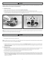
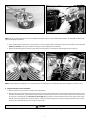
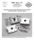
S&S Cycle, Inc
®
Instruction 51-1060
02-18-13
Copyright © 1997, 1999, 2005,
2006, 2010, 2012, 2013
by S&S® Cycle, Inc.
All rights reserved.
Printed in the U.S.A.
.
14025 Cty Hwy G PO Box 215
Viola, Wisconsin 54664
Phone: 608-627-1497 • Fax: 608-627-1488
Technical Service Phone: 608-627-TECH (8324)
Technical Service Email: [email protected]
Website: www.sscycle.com
Installation Instructions: S&S® Super Stock® Cylinder Heads
for 1966–1984 Shovelhead Models
S&S® Super Stock® Cylinder Head Kits for shovelhead models contain all parts needed
for installation of heads. Cylinder heads are available for 31⁄2" and 35⁄8" bore engines
equipped with rubberband or O-ring type manifolds.
1
IMPORTANT NOTICE:
DISCLAIMER:
S&S parts are designed for high performance, closed course, racing
applications and are intended for the very experienced rider only. The
installation of S&S parts may void or adversely affect your factory warranty.
In addition such installation and use may violate certain federal, state, and
local laws, rules and ordinances as well as other laws when used on motor
vehicles used on public highways, especially in states where pollution laws
may apply. Always check federal, state, and local laws before modifying
your motorcycle. It is the sole and exclusive responsibility of the user to
determine the suitability of the product for his or her use, and the user shall
assume all legal, personal injury risk and liability and all other obligations,
duties, and risks associated therewith.
Statements in this instruction sheet preceded by the following words are
of special significance.
WARNING
Means there is the possibility of injury to yourself or others.
CAUTION
Means there is the possibility of damage to the part or motorcycle.
NOTE
Other information of particular importance has been placed in italic type.
S&S recommends you take special notice of these items.
The words Harley®, Harley-Davidson®, H-D®, Sportster®, Evolution®, and all
H-D part numbers and model designations are used in reference only. S&S
Cycle is not associated with Harley-Davidson, Inc.
WARRANTY:
All S&S parts are guaranteed to the original purchaser to be free of
manufacturing defects in materials and workmanship for a period of twelve
(12) months from the date of purchase. Merchandise that fails to conform to
these conditions will be repaired or replaced at S&S’s option if the parts are
returned to us by the purchaser within the 12 month warranty period or within
10 days thereafter.
In the event warranty service is required, the original purchaser must call or
write S&S immediately with the problem. Some problems can be rectified by a
telephone call and need no further course of action.
A part that is suspect of being defective must not be replaced by a Dealer
without prior authorization from S&S. If it is deemed necessary for S&S to
make an evaluation to determine whether the part was defective, a return
authorization number must be obtained from S&S. The parts must be packaged
properly so as to not cause further damage and be returned prepaid to S&S
with a copy of the original invoice of purchase and a detailed letter outlining
the nature of the problem, how the part was used and the circumstances at
the time of failure. If after an evaluation has been made by S&S and the part
was found to be defective, repair, replacement or refund will be granted.
SAFE INSTALLATION AND OPERATION RULES:
Before installing your new S&S part it is your responsibility to read and
follow the installation and maintenance procedures in these instructions
and follow the basic rules below for your personal safety.
Gasoline is extremely flammable and explosive under certain conditions
and toxic when breathed. Do not smoke. Perform installation in a well
ventilated area away from open flames or sparks.
If motorcycle has been running, wait until engine and exhaust pipes
have cooled down to avoid getting burned before performing any
installation steps.
Before performing any installation steps disconnect battery to eliminate
potential sparks and inadvertent engagement of starter while working
on electrical components.
Read instructions thoroughly and carefully so all procedures are
completely understood before performing any installation steps.
Contact S&S with any questions you may have if any steps are unclear or
any abnormalities occur during installation or operation of motorcycle
with a S&S part on it.
Consult an appropriate service manual for your motorcycle for correct
disassembly and reassembly procedures for any parts that need to be
removed to facilitate installation.
Use good judgment when performing installation and operating
motorcycle. Good judgment begins with a clear head. Don’t let alcohol,
drugs or fatigue impair your judgment. Start installation when you are
fresh.
Be sure all federal, state and local laws are obeyed with the installation.
For optimum performance and safety and to minimize potential damage
to carb or other components, use all mounting hardware that is provided
and follow all installation instructions.
Motorcycle exhaust fumes are toxic and poisonous and must not be
breathed. Run motorcycle in a well ventilated area where fumes can
dissipate.
••
••
••
••
••
ADDITIONAL WARRANTY PROVISIONS:
(1) S&S shall have no obligation in the event an S&S part is modified by any
other person or organization.
(2) S&S shall have no obligation if an S&S part becomes defective in whole or in
part as a result of improper installation, improper maintenance, improper use,
abnormal operation, or any other misuse or mistreatment of the S&S part.
(3) S&S shall not be liable for any consequential or incidental damages
resulting from the failure of an S&S part, the breach of any warranties, the
failure to deliver, delay in delivery, delivery in non-conforming condition, or
for any other breach of contract or duty between S&S and a customer.
(4) S&S parts are designed exclusively for use in Harley-Davidson® and other
American v-twin motorcycles. S&S shall have no warranty or liability obligation
if an S&S part is used in any other application.
••
••
••
••
2
INTRODUCTION
S&S® Super Stock® Cylinder Heads for shovelhead models are designed to fit all 1966-1984 shovelhead engines as well as earlier panhead and
knucklehead lower ends equipped with shovelhead cylinders and cylinder heads. The exterior dimensions of S&S cylinder heads for shovelhead
models are the same as stock. With a few minor exceptions, no modification should be necessary when replacing stock cylinder heads with S&S
heads.
NOTE: To reduce exhaust leakage, S&S exhaust ports feature tight fit around the exhaust pipe stub. This may require grinding stubs to reduce O.D. slightly.
Because of variations in castings, minor shimming of the top engine mount may also be required.
NOTE: Some shovelhead rocker housings have thicker walls which reduce clearance for top valve spring retainer. Remove material from inside of rocker
housing to obtain minimum clearance of .060” between housing and S&S top retainer. To maximize rocker housing gasket surface area, relief should be cut
at angle parallel to direction of valve travel rather than vertical. Remove least amount of material possible to obtain proper clearance. See Figures
1 & 2, below.
CORRECT
Figure 1
Shading indicates areas most likely to require modification
for spring retainer clearance. Relief should be cut at an angle,
not vertical.
INCORRECT
Figure 2
Valve compartment of rocker housing (cross section). If required,
relief should be cut at an angle (approximately the same angle as
the valve travel, not vertical). Remove least amount of material
possible to obtain proper clearance
S&S cylinder head kits include all parts needed to install cylinder heads. Customer must supply related replacement items such as intake manifold
o-rings, pushrod cover seals and oil line sleeves. Except in fresh, low mileage engines, S&S recommends checking piston and cylinder wear at time
of cylinder head installation. Even if piston replacement is not required, honing cylinders and replacing piston rings is often beneficial.
Features of S&S Cylinder Heads for Shovelhead Models
•Intake ports feature a directional vane and other changes to increase air flow. At approximately 135 CFM, flow in S&S heads is 10 CFM greater
than best stock heads tested by S&S. Because of variance in OEM castings, in many cases gain will be substantially higher.
•
Available with counterbore for 31⁄2" stock bore or 35⁄8" big bore cylinder.
•
Accept cam cams with valve travel of .590" without coil bind.
NOTE: It is the engine builder’s responsibility to confirm that adequate valve-to-valve and valve-to-piston clearances exist. S&S recommends a
.040" minimum valve-to-valve clearance, and .060" minimum valve-to-piston clearance. S&S cylinder heads for 1966-'84 shovelhead engines will
accomodate cam shafts with valve travel of up to .590" and TDC lifts of up to .210" on both valves
CAUTION
Under no circumstances should engine be forced if resistance is encountered while rotating flywheels to check clearances. Forcing
engine or failing to establish proper clearances can result in extensive engine damage not covered under warranty.
3
•
Shape and volume of combustion chambers is same as stock. Valves and valve seats are compatible with present day fuels.
•
5⁄16-18 cap screws are provided for rocker housing installation.
NOTE: Rocker arm housings must be installed with 5⁄16 -18 cap screws. Harley-Davidson® rocker housing studs are different thread.
NOTE: Some rocker housings require 5⁄16 -18 x 11⁄2" bolts in rear, cam side position of both rocker housings, others utilize 5⁄16 -18 x 21⁄2" bolts in all locations.
See Figure 3, below. S&S kit includes both lengths. Extra 11⁄2" or 21⁄2" bolts will not be used. All rocker housings utilize 11⁄2" bolt in center location between
pushrods.
Figure 3
CAUTION
Attempting to install Harley-Davidson® or similar rocker housing studs in S&S® Super Stock® Cylinder Heads for shovelhead models will
result in damage not covered under warranty.
•
Machining for dual spark plugs and external oil drains is optional.
NOTE: When external oil drain option is specified, S&S blocks stock-style internal oil returns in each head prior to assembly and machines external passages
to accommodate 1⁄8-27 NPT fittings for external return. Fittings are provided but must be installed by customer who must also provide and install the lines
themselves. Return line from each cylinder head should be joined with tee (not provided) approximately at level of crankcase. Third line must then be
attached to tee and routed to primary oil scavenge passage located between oil pump and center of crankcase. See Picture 1. If engine is ever converted
to stock, internal oil return, heads must be disassembled and internal oil passage plugs removed. External passages must also be blocked with 1⁄8-27 NPT
pipe plug.
Picture 1
Primary scavenger fitting location
4
NOTE: Other S&S products such as stroker kits, stock replacement and Sidewinder® big bore cylinders, Super series carburetors, chrome moly steel pushrods,
and solid lifter conversion kits can enhance the performance of shovelhead engines. Many such parts are available in a Hot Set Up Kit® at cost less than that
of individual items purchased separately.
KIT CONTENTS:
•
One set of cylinder head assemblies with valves, valve springs, valve guide seals and keepers installed. Heads are also available bare.
•Rocker housing gaskets, head gaskets, and exhaust flange gaskets. Hardware for rocker housings, top engine mount, carb support bracket, and
exhaust pipes is also provided.
INSTALLATION STEPS
1. Strip Motorcycle
2. Clean and Inspect Parts
3. Install Rocker Housings
4. Install Cylinder Heads
5. Replace Parts Removed for Installation
Installation of S&S Super Stock® Cylinder Heads for shovelhead models is essentially the same as stock. No special tools other than those used in
normal top end repair are required.
In the instructions that follow, references are made to procedures described in an authorized Harley-Davidson® Service Manual. For this reason, a
Service Manual for the appropriate year group and model should be available during installation. Read all instructions thoroughly before beginning,
and proceed only after they are completely understood.
1. Strip motorcycle
Remove battery, gas tanks, exhaust pipes, top engine mount, carburetor, intake manifold, pushrod assemblies, and all other parts required to
remove cylinder heads. Remove cylinder heads, referring to Harley-Davidson® Service Manual as necessary.
WARNING
Sparks from motorcycle electrical system can ignite gasoline fumes. To prevent sparks as well as prevent electric starter from becoming
engaged inadvertently and causing personal injury, disconnect battery and remove from motorcycle before proceeding.
Gasoline is toxic when inhaled, extremely flammable, and explosive under certain conditions. Do not smoke around gasoline, and
perform installation in a well ventilated area away from sparks and open flame.
2. Inspect and clean parts
A. Remove rocker housing assemblies from cylinder head. Disassemble and inspect as explained in Harley-Davidson® Service Manual.
NOTES:
• Pay particular attention to rocker shaft fit in bushings and condition of rocker arm surface that contacts valve tip. Install new shafts or bushings and
reface or replace rockers as needed.
• Unless top end has been rebuilt recently and is known to be in good condition, S&S recommends cleaning and inspecting pistons and cylinders to
determine if wear is within acceptable limits. Regardless of finding, light cylinder hone and new piston rings will prove beneficial for most engines having
more than a few thousand miles of service.
B. Clean housings and other parts thoroughly with solvent, and blow compressed air through oil passages.
NOTES:
• Leaking oil line fittings should be removed and reinstalled with PTFE plumber's tape or other thread sealant. Reassemble rocker assemblies and
housings according to Harley-Davidson® Service Manual, using new rocker shaft o-rings. Lubricate o-rings with assembly lube or light grease to prevent
damage during installation.
• Clean oil feed lines in solvent and blow through with compressed air to remove possible debris and solvent residue. Thoroughly clean head bolt threads
with solvent and wire brush. Replace bolts that are stretched or otherwise damaged and test fit by threading into heads before installation.
5
CAUTION
To prevent inaccurate torque readings and possible damage to cylinder head caused by thread seizure, lubricate head bolt threads with
antiseize compound such as Permatex® Anti-Seize Lubricant before installation. S&S® has received reports of thread damage associated
with other lubricants such as engine oil on head bolt threads.
3. Install Rocker Housings
A.Apply assembly lube to valve tips, also to areas indicated. See Pictures 2 & 3, below.
B. Clean gasket surfaces of cylinder heads and rocker housings with lacquer thinner. Remove residue with clean, dry cloth.
C. Rocker housing gaskets currently supplied by S&S have factory applied silicone on one side. It may face either up or down. Apply thin film
of gasket sealant of choice to other side and allow to cure per manufacturer’s instructions.
Apply assembly lube to areas indicated by arrows
Picture 2
Picture 3
NOTE: S&S has had good results with spray sealants such as Copper Coat® and Permatex® High-Tack. Regardless of type or brand, avoid excessive
sealant which can enter engine and obstruct critical oil passages.
CAUTION
Reduced oil circulation caused by oil passage obstruction can cause extensive engine damage not covered under warranty.
D.Place gaskets and rocker housings on cylinder heads.
NOTE: To maintain rocker arm in correct position, some engine builders place rocker housing upside down on flat surface and lower cylinder head onto
them. Assemblies can then be turned over for installation of hardware.
E.Determine whether 11⁄2" or 21⁄2" bolt is required in rear, camside position (See Figure 3, page 4) and discard other. Place required bolt with
remaining 5⁄16 -18 x 21⁄2" bolts and apply Loctite® 242 (blue) or equivalent to threads of each. Install and tighten in X-pattern to 15-18 ft-lbs.
See Picture 4, next page.
4. Install Cylinder Heads
A.Thoroughly clean cylinder and cylinder head gasket surfaces with lacquer thinner. Remove residue with clean, dry cloth. Apply thin coat of
anti-seize compound such as Permatex® Anti-Seize Lubricant to head bolt threads and area of bolt head that contacts cylinder.
B. Place head gasket on rear cylinder. Confirm that oil passage and head bolt openings line up correctly.
C.Place rear head on cylinder and loosely install two head bolts.
D. Apply PTFE tape or other thread sealant to oil line fittings in crankcase and rocker housings. Install new rubber sleeves on oil lines as needed,
and place overhead oil feed line between crankcase and rocker housing. Loose head bolts will allow head to be raised, eliminating need
to bend oil line. See Picture 5, next page. Loosely install other head bolts. Repeat procedure for front head and install remaining oil line
between rocker housings.
6
Picture 4
Picture 5
NOTE: S&S® has encountered interference between head bolts and cylinder with some imported aftermarket cylinders. S&S head bolts 93-3024 (10 each
required) will usually solve problem.
E.Insert manifold between intake ports, insuring that fit is correct and gaps between manifold and cylinder heads equal on both sides. See
Picture 6, below left. At this point, cylinder heads may be rotated slightly for best manifold fit.
F. Remove manifold and tighten head bolts as described in Harley-Davidson® Service Manual. Recommended torque is 65 ft-lbs.
Picture 6
Picture 7
NOTE: Several head bolts are difficult to reach. Curved wrenches are helpful. They are available from Mac Tools, Craftsman®, and other sources.
5. Replace Parts Removed for Installation
A. Replace manifold o-rings or bands as needed, and install manifold.
B. Remove nuts from drive side of intake rocker shafts, taking care not to misplace thin washers. Install top engine mount with 7⁄16-14 x 11⁄4" bolts
provided. Use washers to fill any gap between engine mount and cylinder heads or frame. In some instances, customer-provided shims may
be required to completely fill gap. See Picture 7, above right. Once proper fit has been established, remove bolts, apply Loctite® 242 to
threads, and reinstall. Tighten bolts in head to 54 ft-lbs. Frame bolt should be tightened according to torque specification chart in HarleyDavidson® Service Manual. Replace rocker shaft nuts and washers.
CAUTION
Failure to properly shim engine mount can cause vibration and stress resulting in damage to engine or frame.
7
C. Install pushrods with cover assemblies. Adjust pushrods according to manufacturer’s instructions and install cover retainer clips.
D. Install carburetor, air cleaner, and support bracket according to manufacturer’s instructions.
WARNING
Fuel supply and overflow lines must not contact hot surfaces which could melt line, resulting in gasoline leakage and possible fire hazard.
All clamps must be tight to prevent gasoline leak. Refer to warnings on page 2 concerning gasoline hazards.
E. Using gaskets, lock washers, and socket head cap screws provided, install exhaust. Exhaust system must also be bracketed to frame for
adequate support.
F. Gap and install spark plugs. Heads accept standard 14-1.25mm, 3⁄4" reach sparkplugs. Camside sparkplug in dual plug heads will usually be
same heat range as other.
G. Start motorcycle and observe for gasoline and oil leaks.
6.Tuning
A.Carburetor
Because S&S® heads will probably flow significantly more air than heads removed, carburetor may require larger jets for best performance.
Consult carb manufacturer’s instructions for tuning procedure.
B. Ignition Timing
No adjustment should be required for single spark plug cylinder head. Overall ignition timing should be retarded 5-10 degrees in most dual
plug applications. In general, excessive ignition advance will cause engine to kick back against starter during start-up and “buck” when ridden at steady speed
with partial throttle. An advanced condition can also cause pinging or ignition knock and possible piston damage. Some symptoms may not
be noticeable if an electronic ignition with a “soft” advance curve is used. Excessive ignition retard causes sluggish performance and severe
overheating with possible subsequent damage to the engine, and must also be avoided. Immediate or rapid exhaust pipe discoloration is
usually a sign of retarded ignition timing.
CAUTION
Pinging or ignition knock can be an early sign of detonation and possible impending engine damage. Should pinging occur, the throttle
must be backed off and the cause determined and corrected. Excessive retard is less obvious but equally destructive. For that reason,
final timing should be confirmed with a timing light or other accepted procedure.
WARNING
Incorrect ignition timing can cause extensive engine damage not covered under warranty.
7.Break-in
Because of tight fit of new valves and guides, engine should be ridden 1000-2000 miles before subjected to excessive heat caused by traffic,
heavy load, high speed operation, etc. If rings or pistons replaced, break in as follows:
A. First 50 miles are critical for new rings and pistons. Most engine damage occurs during this period. Keep heat down by avoiding heavy traffic
and not exceeding 2500 RPM or approximately 50-60 MPH, depending upon gearing, during this time. Vary speed and do not lug engine.
Change oil and filter at 50 miles.
NOTES: S&S recommends that the cylinder base nuts and head bolts should be retightened after engine has been run and reached normal operating
temperature.
B. For next 500 miles, engine may be taken to 3500 RPM or approximately 60-70 MPH (depending upon gearing) for brief periods. Speed
should be varied, and lugging and heavy traffic avoided. Change oil and filter at end of first 500 miles.
C.Modest increases in speed are permissible during next 1500 miles. Engine should not be given full throttle, and heavy loads such as trailers
and sidecars avoided. Some operation at in-town speeds (40-45 MPH) is recommended, although lugging and heavy traffic should still be
avoided. Change oil and filter at 500 mile intervals until 2000 miles.
D. The following is mandatory at 2000 miles and thereafter: HAVE FUN! Oil and filter should be changed every 2000 miles after break-in, more
often if oil appears dirty or engine is subjected to extreme temperatures or dusty conditions, ridden for only short periods of time, or
frequently operated in heavy traffic.
8
S&S® Super Stock® Cylinder Heads Replacement Parts
13. Flat washer - 7⁄16" x 15⁄16" x 1⁄8" (H-D® #6495HW) . . . . . . . . . . . . 50-7064
14. Rocker cover mounting screw - 1966-’84 BT
1. Cylinder head . . . . . . . . . . . . . . . . . . . . . . . . . . . . . . . . . . . . . . . . . . See Chart Below
2. Valves
Intake
1.950" (H-D® #18075-80, 18075-81, 18078-80, 18078-81)
. . . . . . . . . . . . . . . . . . . . . . . . . . . . . . . . . . . . TÜV 90-2015
1.950" +.005" . . . . . . . . . . . . . . . . . . . . . . . . . . . . . . . . . . . . . 90-2020
Exhaust – 1948-'84 BT
Hex head - 5⁄16"-18 x 21⁄2" (H-D® #3501) (each) . . . . . . . . . . . . . 50-0104
3
5 pack. . . . . . . . . . . . . . . . . . . . . . . . . . . . . . . . . . . . . . . . . 50-1000
15. Flat washer - 5⁄16" (H-D® #6016, 6702) . . . . . . . . . . . . . . . . . . . . 50-7034
16. Rocker cover gasket 1966-’84 BT (H-D® #17540-69)
TÜV390-2022
1.720" (H-D® #18086-80, 18086-81, 18089-80, 18089-81. . .
1.720" +.005" stem diameter. . . . . . . . . . . . . . . . . . . . . . . . 90-2031
3. Valve seats
Intake – 1.940"
Standard (H-D® #18020-79). . . . . . . . . . . . . . . . . . . . . . . . . TÜV390-2017
+.002" oversize. . . . . . . . . . . . . . . . . . . . . . . . . . . . . . . . . . . . . . . . . N/A
+.010" oversize. . . . . . . . . . . . . . . . . . . . . . . . . . . . . . . . . . . . 90-2117
Exhaust – 1.750"
Standard (H-D® #18010-79, 18055-66B). . . . . . . . . . . . . . . . TÜV390-2018
+.002" oversize . . . . . . . . . . . . . . . . . . . . . . . . . . . . . . . . . . . 90-2119
+.010" oversize . . . . . . . . . . . . . . . . . . . . . . . . . . . . . . . . . . . 90-2121
4. Valve guide - cast - 1980-’84 BT
Intake or Exhaust
Standard. . . . . . . . . . . . . . . . . . . . . . . . . . . . . . . . USA TÜV390-2240
+.001" (H-D® #18109-81A). . . . . . . . . . . . . . . . . . . . . . . . USA 90-2241
+.002" (H-D® #18108-81A). . . . . . . . . . . . . . . . . . . . . . . . . USA 90-2242
+.003" (H-D® #18107-81A). . . . . . . . . . . . . . . . . . . . . . . . . USA 90-2243
+.004" (H-D® #18106-81A). . . . . . . . . . . . . . . . . . . . . . . . . USA 90-2244
+.006" (H-D® #18110-81A) . . . . . . . . . . . . . . . . . . . . . . . . USA 90-2246
+.060" . . . . . . . . . . . . . . . . . . . . . . . . . . . . . . . . . . . . . . USA 90-2249
5. Valve guide seal – intake or exhaust
1981-’84 BT (H-D® #18000-81) (each) . . . . . . . . . . . . . . . . USA 90-2019
8 pack. . . . . . . . . . . . . . . . . . . . . . . . . . . . . . . . . . . . . . . . USA 90-2157
6. Valve spring shim - Late 1981-’84 BT
.005" x .765" x 1.500". . . . . . . . . . . . . . . . . . . . . . . . . . . . . . . 50-7121
.015" x .765" x 1.500". . . . . . . . . . . . . . . . . . . . . . . . . . . . . . . 50-7122
.025" x .765" x 1.500" (each). . . . . . . . . . . . . . . . . . . . . . . . . . 50-7123
5 pack. . . . . . . . . . . . . . . . . . . . . . . . . . . . . . . . . . . . . . . . . . . . . . 50-7160
7. Valve spring kit – Late 1981-'84
Hex head - 5⁄16"-18 x 11⁄2" (H-D® #2818) (each) . . . . . . . . . . . . . 50-0109
10 pack. . . . . . . . . . . . . . . . . . . . . . . . . . . . . . . . . . . . . . . . . . . . 50-0196
each . . . . . . . . . . . . . . . . . . . . . . . . . . . . . . . . . . . . . . . . . . . . . .
90-4040
10 pack . . . . . . . . . . . . . . . . . . . . . . . . . . . . . . . . . . . . . . . . . . . . . . . . . . . . . 90-4064
17. Intake manifold (See page 5-72)
18. Manifold seal
O-ring - 1955-’78 BT (H-D® #27060-55)
each. . . . . . . . . . . . . . . . . . . . . . . . . . . . . . . . . . . . . 50-8046
10 pack. . . . . . . . . . . . . . . . . . . . . . . . . . . . . . . . . . . . . . . . 50-8132
Band - 1979-’84 BT (H-D® #27062-78)
each . . . . . . . . . . . . . . . . . . . . . . . . . . . . . . . . . . . . . . . . . USA 16-0238
10 pack. . . . . . . . . . . . . . . . . . . . . . . . . . . . . . . . . . .
USA
16-0245
19. Manifold mounting clamp
O-ring type heads - 1955-’78 BT (H-D® #27063-57). . . . TÜV 316-0230
Band type heads - 1979-’85 BT (H-D® #27063-78, 27063-80). USA 16-0231
20. Head bolt assembly, stainless - 1948-’84 BT
(Includes head bolt & washer.) (H-D® #16814-77, 6469HW)
10 pack. . . . . . . . . . . . . . . . . . . . . . . . . . . . . . . . . . . USA 93-3024
21. a. Head Bolt, each. . . . . . . . . . . . . . . . . . . . . . . . . . . . . . . . . 93-3024-S
b. Head bolt washer - 1936-’84 BT
(For part #90-3024, #90-3026 & #90-3040). . . . . . . . . . . . . . . . TÜV 393-3025
22. Head gasket, copper - 1966-’84 BT
37⁄16" & 31⁄2" bore (H-D® #16770-66B) (each) . . . . . . . . . . . . . . . 93-1041
10 pack. . . . . . . . . . . . . . . . . . . . . . . . . . . . . . . . . . . . . . . . . . . . . 93-1061
35⁄8" bore (each). . . . . . . . . . . . . . . . . . . . . . . . . . . . . . . . . . . . 93-1042
10 pack. . . . . . . . . . . . . . . . . . . . . . . . . . . . . . . . . . . . . . . . . . . . . 93-1062
23. Fitting, oil return, 1⁄8"-27 pipe (H-D® #63533-65). . . . . . . TÜV331-2019
24. Plug, oil return, 1⁄8"-27 pipe (each). . . . . . . . . . . . . . . . . . . . . 50-8331
10 pack. . . . . . . . . . . . . . . . . . . . . . . . . . . . . . 50-1015
N/A= No longer available
(Includes springs, top & bottom collars, keepers shims)
.590" lift - steel top collars. . . . . . . . . . . . . . . . . . . . . . . . . . . 90-2063
.590" lift - titanium top collars . . . . . . . . . . . . . . . . . . . . . . . 90-2064
8. Valve spring keeper – intake or exhaust
1936-’84 BT (H-D® #18228-36) (each) . . . . . . . . . . . . . . . . . . . . 90-2037-S
8 pack. . . . . . . . . . . . . . . . . . . . . . . . . . . . . . . . . . . . . . . . . . . . . . 50-7165
9. Screw, SH - 5⁄16"-18 x 1" (H-D® #2708A). . . . . . . . . . . . . . . . . . . 50-0101
10. Lock washer - 5⁄16" (H-D® #7041) . . . . . . . . . . . . . . . . . . . . . . . . 50-7032
11. Exhaust pipe gasket - 1966-’84 BT (H-D® #653834-68A)
each . . . . . . . . . . . . . . . . . . . . . . . . . . . . . . . . . . . . . . . . . . . . . 93-1004-S
10 pack. . . . . . . . . . . . . . . . . . . . . . . . . . . . . . . . . . . . . . . . . . . . . 93-1075
12. Head mount bolt - 7⁄16"-14 x 11⁄4"(H-D® #3782) (each) . . . . . . . 50-0171
10 pack . . . . . . . . . . . . . . . . . . . . . . . . . . . . . . . . . . . . . . . . 50-0228
S&S® CYLINDER HEAD KITS FOR 1966–'84 BIG TWIN ENGINES
Engine Year
and Type
Stock
35/8"
35/8" Dual Plug
Stock
1979–'84
35/8"
(Band)
35/8" Dual Plug
Special Order*
Specify
1966–'78
(O-ring)
All reference to Harley-Davidson® part numbers is for identification purposes
only. We in no way are implying that any of S&S® Cycle’s products are
original equipment parts or that they are equivalent to the corresponding
Harley-Davidson part number shown..
9
Bore
Complete with Valves & .590" Springs - Assembled
Aluminum Finish
Black Powdercoat Finish
90-1496
90-1596
90-1497
90-1597
90-1491
–
90-1498
90-1598
90-1499
90-1599
90-1488
–
90-1490**
*Use this special order part number to order assembled or unassembled cylinder heads with spring
options, and special finish. Front or rear heads available by special order.
**Special Order: Download the Special Order Form at sscycle.com/soforms
8
7
12
14
13
15
14
6
5
15
9
4
16
10
11
1
24
17
23
19
18
22
3
21b
2
20
21a
10