Transcript
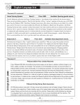
ElectroSport Industries
3803 Oceanic Drive,
Ste 201
Oceanside, CA 92056
Phone: 760-842-8300
Fax: 760-842-8306
www.electrosport.com
ESG432 / ESG434 Stator
Fitting Instructions
Applications
Yamaha Utility ATV/UTV Models
Visual Inspection Notes
The stock OEM stator is shown
on the left and the replacement
is shown on the right. Visually
they will look different, but it is
for good reason. The replacement
part is designed with two of the
poles wound for the ignition.
This is a significant advantage
for keeping the ignition running
cooler.
Fitting Replacement Part
Stock stator
Follow procedures in your service manual to remove your old part.
Once you have the stock part removed, fit the replacement part and follow the installation
procedures as specified in the service manual. Pay particular attention to the torque
specifications required to insure proper and secure mounting. If for any reason you are unsure
of the process, consult a qualified mechanic at your local dealership or service center.
Replacement stator
Small Tab
Trouble Shooting Procedure
Green and aqua wire swap: If for any reason the engine does not start, first double check
all of your connections making sure they are fully seated. If the engine still fails to start, you
may need to swap the GREEN and AQUA wires. To do this, looking into the female connector
and using the tip of a very small flat bladed screwdriver, you need to lift up each of the small
tabs directly above the metal spade on each wire as shown in Figure A. Pull the wire and
grommet out from the plastic connector as shown in Figure B. Then swap the wire locations
and push each wire and grommet securely into the connector. Try the engine and see if it will
start. If, not swap the wires back to the original position and reconnect the connector.
Figure A
Pull wire and grommet
out from connector
There are four other known causes for the engine to fail to start:
Check Neutral Relay and Starting Circuit Cut-Off Relay per manufacturer service manual
directions to ensure proper operation. Relays often fail due to vibration, moisture, and age and
will prevent this vehicle from starting.
Neutral gear switch test: If after swapping the GREEN and AQUA wires the engine fails to
start, one-by-one pull off the NEUTRAL GEAR wires from the switch and run a jumper wire
between those two wires (Figure C) and see if the engine will start. If not, put it back together.
Figure B
Clutch starter switch test: If after testing the Neutral Gear Switch, the engine fails to start,
pull off the Clutch Starter wires from the clutch switch and run a jumper wire between those
two wires ( Figure C) and see if the engine will start.
Run jumpers on both switch wires: If the engine still fails to start you need to check and
run jumper wires on both switches individually at the same time. By process of elimination,
with testing each or both you should be able to define which switch may need replacement.
WARNING: Never operate the vehicle with either the Neutral Gear Switch or the Clutch Starter
Switch disabled. You must have these switches fully operational prior to riding the vehicle.
Switch Wiring
Jumper Wire
Figure C
Switch