1
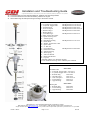
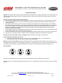
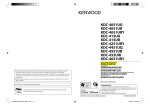
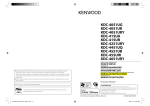
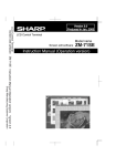
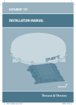
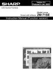
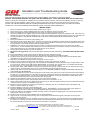
Installation and Troubleshooting Guide
All rights reserved. Reproduction or use of content, in any manner, without express written permission by CDI Electronics, Inc., is prohibited.
CDI P/N: 134-3736
This unit replaces P/N’s: 332-4177A 3,393-3736A 3,393-3736A23, 393-3736A77, and 393-3736A79
NOTICE: THIS TRIGGER REQUIRES THE STEEL DISK INCLUDED WITH IT. IT WILL NOT WORK WITH THE FACTORY DISK!!
Warning! This product is designed for installation by a professional marine mechanic. CDI cannot be held liable for injury or damage
resulting from improper installation, abuse, neglect or misuse of this product. Refer to the Service Manual to set ignition timing.
DO NOT USE A MAINTAINENCE FREE OR LOW MAINTAINENCE BATTERY WITH THIS SYSTEM. BATTERY VOLTAGE IN
EXCESS OF 16 VOLTS MAY DAMAGE IGNITION PARTS (NOT COVERED UNDER WARRANTY).
INSTALLATION
1.
2.
3.
4.
5.
6.
7.
8.
9.
10.
11.
12.
13.
14.
15.
16.
17.
18.
19.
20.
21.
22.
23.
24.
25.
26.
27.
28.
Remove the electrical harness and the battery leads from the engine.
Disconnect the brown, white and black trigger wires (from the distributor body to the switch box).
Remove the distributor housing assembly from the engine according to the service manual.
Remove the distributor cap retainer clamp and screw and then lift the distributor cap from the distributor body. Take care not to
damage the carbon brush inside the distributor cap. If the rotor is damaged and requires replacement, the rotor and shaft must
be replaced together. THE ROTOR IS MADE ONTO THE SHAFT AND CANNOT BE REPLACED EXCEPT AS AN
ASSEMBLY.
Remove the distributor vent tube or spark arresting vent.
Bend the tabs of the cap nut washer open. Unscrew the cap nut from the distributor housing. Remove the tabbed washer and
wave spring. Work the tension spring off of the pin as you slide the distributor housing from the mounting adapter. Do not lose
the large washer or the smaller washer inside the adapter housing.
CAREFULLY remove the upper bearing from the housing by working through the two holes in the sides of the housing.
Remove the ¾” nut from the shaft while holding the rotor. Use extreme care not to break the rotor tip or twist the rotor on the
shaft. If this happens, the rotor and shaft assembly will have to be replaced.
Using a plastic mallet, GENTLY tap the rotor shaft free.
Discard the old trigger disk, saving the old disk spacer (between the disk and bearing). YOU MUST USE THE NEW STEEL
DISK!
Inspect the distributor cap and carbon brush for damage and wear. Replace if needed.
Using a punch, knock out the tension spring pin. Remove the tension spring and throttle stop plate.
Install the tension spring pin (using a good thread-locker in the distributor housing), tension spring and throttle stop plate.
Remember the spring must be free to rotate on the pin.
Support the new distributor housing between two blocks of wood in a vise.
Remove the two mounting screws from the new distributor housing cap and set the cap aside.
Install the old disk spacer, new trigger disk and rotor shaft into the distributor housing. Align the tang in the disk with the notch
in the rotor shaft. Make sure the side marked “ROTOR SIDE” is facing the rotor. Service Note: On a double notched shaft,
the wide notch is for a 4 cylinder disk and the narrow notch is for the 6 cylinder engines.
Using a plastic mallet, VERY CAREFULLY tap the rotor shaft into the housing. Continue work the rotor shaft into the housing
until the collar on the shaft seats into the recess in the distributor (the disk should not be loose).
Slide the tube spacer onto the shaft and secure with the ¾” nut. BE VERY CAREFULL WHEN TIGHTENING THE NUT OR
THE ROTOR MAY BE DAMAGED.
Remove the distributor from the vise and gently tap the rotor shaft on the pulley end in order to seat the lower bearing against
the snap ring. Turn the housing over and check the clearance between the disk and the new distributor housing. If the disk is
touching the new distributor base, you will need to dissemble the distributor housing and replace the old disk spacer with a
new one (994-3538-10 spacer is 0.010 inches taller than the original).
Replace the new distributor housing cap using the two screws removed earlier.
Slide the upper bearing onto the rotor shaft and work it down until it contacts the ¾” nut.
Slide the large washer onto the new distributor housing and as you slide the adapter housing onto the new distributor housing,
connect the tension spring to the adapter housing pin.
Install the small ring washer, wave spring and cap washer. Thread the cap nut on and bend the tabs of the adapter cap
washer to lock the adapter cap in place.
Install the distributor vent tube or spark arresting vent.
Place the distributor cap assembly onto the distributor housing. BE CAREFULL not to bend the carbon brush sparing or
damage the carbon brush. Position and install the distributor clamp and retainer with the bolt and nut.
Position the distributor and distributor adaptor assembly onto the powerhead mounting flange. Check to be sure the driven
pulley spacer and key are in place.
Install the three screws securing the distributor to the powerhead block.
Align the arrow on the pulley with the timing mark on the flywheel and install the timing belt, timing belt cover and screw
(tighten to 60 inch pounds).
Install the ground strap and connect the Black ground wire to the engine block. Connect the Black, Brown and White wires to
the switch box, matching wire colors to the terminals. If the switchbox has stud terminals, push in the ring adapter terminals
into the female bullet connectors to convert the wire connections to a ring type.
CDI Electronics • 353 James Record Road SW • Huntsville, AL 35824
Web Support: www.cdielectronics.com • Tech Support: 1-866-423-4832 • Order Parts: 1-800-467-3371
All rights reserved. Reproduction or use of content, in any manner, without express written permission by CDI Electronics, Inc., is prohibited.
Rev B • 1/08/13
Page - 1 of 3
QF-319
Installation and Troubleshooting Guide
All rights reserved. Reproduction or use of content, in any manner, without express written permission by CDI Electronics, Inc., is prohibited.
29. Connect the link rod to the vertical throttle lever. Install the cowl mounting brackets.
30. Connect the electrical connections and battery cables to the engine.
31. Set the idle timing and wide open timing according to the service manual.
1 – Rotor Shaft
CDI Replacement # 994-4371
2 - 6 Cylinder Trigger Disk*
CDI Replacement # 134-4313-S
3 – 4 Cylinder Trigger Disk*
CDI Replacement # 134-3236-S
4 – Original Spacer
CDI Replacement # 994-3538
5 – Over-size Spacer
CDI Replacement # 994-3538-10
6 – Retainer Ring**
CDI Replacement # 994-6406
7 – Bearing Shim**
8 – Lower Bearing**
CDI Replacement # 994-6379
9– Spark Advance Stop Plate
10 – Spark Arresting Vent
11 – Tension Spring
12 – Distributor Housing
CDI Replacement # 134-3736
13 – Plastic Shim
14 – Washer, Economizer Collar
15 – Spacer Tube
16 – ¾” Hex Nut
17 – Upper Bearing
CDI Replacement # 994-0066
18 – Economizer Collar
19 – Adapter Housing
20 – Wave Spring
21 – Tab Lock Washer
22 – Metal Shim Washer
23 – Cap Nut
* Included with the new distributor housing.
** New distributor housing comes with these parts installed.
Distributor Service Kits
994-1111K1
Installation Kit
1 - 6 Cylinder Trigger Disk # 134-4313-S
1 – 4 Cylinder Trigger Disk # 134-3236-S
1 – Retainer Ring
# 994-6406
1 – Original Spacer
# 994-3538
1 – Over-size Spacer
# 994-3538-10
1 – Lower Bearing
# 994-6379
1 – Upper Bearing
# 994-0066
994-1111K2
Bearing Kit
1 – Retainer Ring
1 – Lower Bearing
1 – Upper Bearing
# 994-6406
# 994-6379
# 994-0066
CDI Electronics • 353 James Record Road SW • Huntsville, AL 35824
Web Support: www.cdielectronics.com • Tech Support: 1-866-423-4832 • Order Parts: 1-800-467-3371
All rights reserved. Reproduction or use of content, in any manner, without express written permission by CDI Electronics, Inc., is prohibited.
Rev B • 1/08/13
Page - 2 of 3
QF-319
Installation and Troubleshooting Guide
All rights reserved. Reproduction or use of content, in any manner, without express written permission by CDI Electronics, Inc., is prohibited.
TROUBLESHOOTING
NOTICE: The trigger cannot be bench tested except with the CDI Electronics Trigger Tester P/N: 511-9710 (the tester can
also be used to test the trigger while on the engine). Be sure to follow the instructions at the bottom when lining up the
rotor and disk.
Dead or no spark until you let off of the key switch:
1. Clean ALL engine ground wires from the battery thru the engine cowling, splash pan, top cowl and support brackets.
2. Verify that there is at least 9-1/2 volts on the White wire going to the switch box (from the engine harness) while
cranking the engine.
3. Verify that there is at least 9 volts on the Brown wire going to the trigger while cranking the engine. If the voltage is
low and the voltage on the White wire from the harness is above 9-1/2 volts, disconnect the wires from the switchbox,
then check the resistance from the White terminal beside the Red terminal (from the White/Red wire on the CDI
Electronics switchbox) to the Brown terminal going to the trigger. You should read 60-76 ohms. A high reading
indicates a possible bad switchbox.
4. Check resistance between the White wire and engine ground. It should read less than 1 ohm. If it reads higher, make
sure the Black ground wire is connected to engine ground.
5. Connect a secondary ground wire (12 gauge) from the negative battery cable to the base (or case) of the switch box.
6. Using the 511-9710 Trigger Tester, check the output of the trigger according to the directions for the tester.
Only has spark as long as the starter is engaged: Usually indicates a bad trigger. Test per above.
Fires all cylinders but engine will not run:
1. Recheck sensor wheel to make sure it is right side up. See diagrams below for correct placement.
2. Check the ground wire from the starter mounting to the support plate.
Misses on one or more cylinders: Connect spark gap checker to all cylinders, align the rotor to each cylinder in turn,
and trigger the pack using the 511-9701 Battery CD Tester. If a cylinder fails to fire, or if another cylinder fires besides the
one that the rotor is pointed to, replace the distributor cap. Watch for spark plug wires arcing to the engine block.
Disk assembly:
Note: On 6 cylinder engines, the tip of the rotor must split the right hand side of the opening in the disk.
Service Note: On a double notched shaft, the wide notch is for a 4 cylinder disk and the narrow notch is for the 6 cylinder
engines.
CDI Electronics • 353 James Record Road SW • Huntsville, AL 35824
Web Support: www.cdielectronics.com • Tech Support: 1-866-423-4832 • Order Parts: 1-800-467-3371
All rights reserved. Reproduction or use of content, in any manner, without express written permission by CDI Electronics, Inc., is prohibited.
Rev B • 1/08/13
Page - 3 of 3
QF-319