1
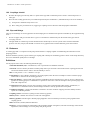
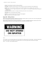
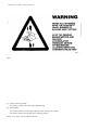
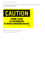
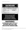
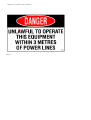
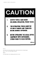
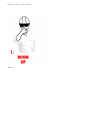
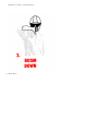
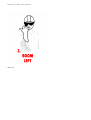
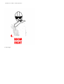
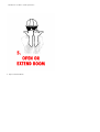
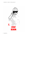
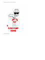
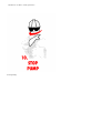
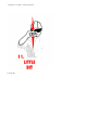
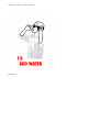
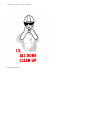
WorkCover on Disk - Codes of Practice
CODE OF PRACTICE
Construction Testing Concrete Pumps
gazetted 26 November 1993, commenced 1 March 1994
1. Introduction
1.1 Citation
This Code of Practice may be cited as, Code of Practice, Construction and testing of concrete pumps 1993.
1.2 Purpose
This Code of Practice sets out guidelines for the construction and testing of concrete pump units and placing booms, pipes, hoses
and couplings.
1.3 Scope
This Code applies to pump units, placing booms and ancillary equipment used for the conveyance of concrete where the pump
unit is skid mounted, trailer mounted or vehicle (prime mover) mounted.
1.4 Commencement
This Code of Practice commences on 1 March 1994
1.5 Authority
This Code of Practice is approved as an Industry Code of Practice pursuant to section 44A of the Occupational Health and Safety
Act, 1983, by the Minister of Industrial Relations and Employment on the recommendation of the WorkCover Authority of NSW.
2. Pump unit
Dangerous parts should be safeguarded as far as practicable in accordance with the Occupational Health and Safety Act, 1983 and
Regulations.
2.1 Mounting
a.
Skid mounted - lifting eyes, or fittings for attaching lifting gear, should be provided to ensure the safe handling of the pump
unit by crane. A clearly visible permanent notice indicating the overall weight should be fixed to the unit.
b.
Trailer mounted - Trailers should be constructed in accordance with RTA regulations if the unit is designed for towing on
public roads.
c.
Vehicle mounted - the vehicle and equipment should comply with RTA regulations and be fitted with an audible reverse
warning device. A permanent notice should be fixed in the driver’s cab to indicate the maximum height of the unit in
travelling order.
d.
Concrete pump and boom manufacturers, or firms responsible for mounting these components on vehicles, should ensure that
the vehicle selected is suitable for the equipment to be mounted. In particular, the vehicle should be assessed for:
(i)
Axle loadings and gross vehicle weight including any additional weight of ancillary equipment such as a full water tank
for routine tasks, pipes, hoses and couplings.
(ii) Power/weight ratio.
(iii) Performance on the highway.
(iv) Performance under site conditions.
(v) Stability, both on the highway and under site conditions.
(vi) Torsion of chassis frame.
WorkCover on Disk - Codes of Practice
(vii) Engine cooling.
(viii)Auxiliary power takeoff(s).
2.2 Outriggers
Mobile or trailer mounted pumps should have outriggers, jacks or axle locks to provide stability during pumping operations. A
permanent notice should be fixed at a point near each outrigger on mobile boom pumps, indicating the maximum force in kN that
can occur at the foot of a fully extended outrigger. See Appendix - Safety stickers.
2.3 Receiving hopper
The receiving hopper should be positioned on the mounting so that it can receive concrete flow readily from the discharge chute of
the truck mixer.
A hinged grill should be provided to prevent access to dangerous moving parts such as feed or agitator mechanisms and valve
gear. The grill should be constructed of parallel bars, spaced so that it is not possible for a person’s hand to become trapped.
Spacing should not exceed 70mm and the distance from grating to moving parts should be a least 150mm.
2.4 Access steps and working platforms
Access steps and working platforms should be designed for the operator’s safety.
3. Placing booms and boom pipelines
3.1 Placing booms
Placing booms and associated slewing mechanisms and mounting should be designed and constructed to withstand the static and
dynamic loads to which they may be subjected in use. The effects of fatigue, wind loadings and service factors should also be
taken into account.
Design should allow for the use of suitable placement hoses. Lengths of hoses should be in accordance with manufacturers’s
recommendations. Where booms are mounted on separate bases or tower structures these should also be suitably designed and
adequately mounted. Provision should be made to secure the boom in the stowed position for travelling.
Many aspects of the design of placement booms is similar to cranes. The appropriate sections of AS1418 - SAA crane code or
DIN 24117 - Machines for the building and building materials industry should therefore be applied to the design of placing booms
for concrete pump units.
3.2 Boom pipelines
Each section of rigid pipeline or flexible hose should be anchored to the booms so that in the event of a coupling failure, no
section of pipe or hose can fall from the boom. Metal pipe swivels should be fitted in place of flexible hoses to accommodate the
folding of boom sections. (Delivery pipes and flexible hoses supported by the boom and their adaptors and couplings should be as
specified in sections 10 and 11.)
3.3 Pipeline - security and reactions
Concrete pumping lines are secured to the building or structure to withstand the often powerful reaction forces from high pump
pressures. It is essential that the reaction blocks or mountings at changes of direction of pipelines are designed to withstand these
forces.
3.4 Safety fittings
Use chains, wire ropes or webbing slings as a safety measure to secure sections of pipe such as reducers, rubber hoses and bends
which are liable to fail at the joint when attached to the final outlet of boom drop hose. Safety chains, wire ropes or webbing
slings should have a minimum safe working load of 1,200kg. Reducers should have compensation plates to which the anchorages
are welded.
4. General design requirements
WorkCover on Disk - Codes of Practice
Concrete pumps and concrete placing booms should comply with the applicable engineering standards. Modifications are allowed
only if the required safety standards are met. Wherever possible, before modifications are made seek the advice of the
manufacturer.
4.1 Guarding
All exposed moving parts should be guarded to prevent any body part making contact with any moving part. Truck engines that
drive concrete pumps should not be able to be started from the control panel of the concrete pump. An exception is for engines
that can only be started with all gears in neutral.
4.2 Marking
The following information should be displayed.
a.
Concrete pumps:
(i)
Manufacturer or supplier
(ii) Year of manufacture
(iii) Serial number
(iv) Model or type
(v) Maximum permissible operating pressure of the pump hydraulic system (in bar)
(vi) Maximum concrete pipeline pressure (in bar).
b.
Concrete placing booms:
(i)
Manufacturer or supplier
(ii) Year of manufacture
(iii) Serial number
(iv) Model or type
(v) Maximum permissible operating pressure of the boom hydraulic system (in bar)
(vi) Maximum permissible pipeline internal diameter in millimetres and maximum hose length in meters
(vii) Any restrictions on specified areas of operation.
4.3 Safety stickers
Safety stickers for pumps, boom pumps and tower booms should be affixed to equipment in accordance with schedule contained
in Appendix - Safety stickers.
5. Hydraulic operation of the pump and boom
5.1 General
The specification and construction of hydraulic systems should be designed for the safety of personnel and long life of equipment.
5.2 Horizontal stabilisers (outriggers)
Outriggers should have positive locking when fully extended or retracted.
5.3 Hydraulic cylinders
Hydraulic cylinders on concrete placing booms and hydraulic outriggers should be fitted with controllable non-return valves so
that the pressure in the hydraulic cylinder is maintained if a hose or pipe bursts. A connecting pipeline between any cylinder and
respective controllable non-return valve is prohibited.
6. Controls
6.1 Markings
WorkCover on Disk - Codes of Practice
Controls should be clearly marked with symbols or words (in English) to show their function. Where practicable the direction of
movement of a control should correspond with the direction of motion being controlled. (See Appendix - Safety stickers for
recommended symbols.)
6.2 Control selections
The control system should be arranged so that control selections cannot cause a motion not intended by the operator, unless
essential for the operation of a safety device or interlock.
6.3 Dead man controls
Where there is more than one set of controls, the pump unit should be operable from only one position at any time. Controls for
slewing, luffing and folding the boom should automatically return to the OFF position when the lever or knob is released by the
operator. All controls (including remote controls) should be full ’dead man’ so that in the event of operator release they return to
neutral and lock-in position.
6.4 Radio controls
All full radio remote control systems should be approved by Telecom with a closely monitored transmitting frequency unique to
the one machine. It is essential that interference is not possible from another machine or from other sources that could
accidentally operate the machine by remote control. Controls should be water tight to prevent water leaking into electrical switch
contacts causing an unselected movement of the control due to circuit "bridging".
6.5 Controls mounted on pump unit
The controls should be positioned so that the operator has a clear view of the receiving hopper and of the placing boom (if fitted).
The control station should be located so that the operator cannot be struck by the boom when using the controls. Steps and
handholds should be provided to give safe access to platforms or seats.
6.6 Hydraulic controls
For hydraulic powered engines the main control panel should include a gauge to indicate the pressure of the fluid supplied to the
concrete pumping mechanism. Where a hydraulic accumulator is installed or, if the valve is controlled by a separate hydraulic
circuit, the panel should also include a gauge to indicate pressures of fluid supplied to the valve mechanism. Each gauge should
be clearly labelled.
7. Pump unit stability testing
7.1 Testing standard
All tests should be carried out in accordance with DIN 24117 or the stability test procedure laid down by the manufacturers.
7.2 Test weights
Test weights should be suspended at points along the boom as specified by the manufacturer.
7.3 Test conditions
When conducting a stability test the amount of fuel oil and the volume of washing water in the tanks should be the most
unfavourable to the stability of the machine.
7.4 Stability tests
Stability tests should be carried out by the boom manufacturer or their qualified representative before putting a newly
manufactured concrete placing boom into service. Stability tests should also be carried out whenever modifications are made to a
concrete placing boom or boom-type concrete pump that may affect stability. The results of all stability tests should be recorded
in the machine’s log book.
8. Noise
8.1 Noise levels
WorkCover on Disk - Codes of Practice
Concrete pumps should be constructed to ensure the minimum possible noise levels during operation.
9. Instruction and service manuals
Instruction manuals should be supplied with the pump unit and boom, giving comprehensive instructions for operation, testing,
maintenance and repair and include a parts catalogue.
A service manual should be supplied with the pump unit and boom detailing the frequency and type or service to be carried out.
Manufacturers and suppliers of pump units and booms should notify the pump owners of any alterations or additions to these
manuals.
10. Delivery pipelines
10.1 General
Manufacturers of concrete pumps and placement booms are responsible for specifying the internal diameter and wall thickness of
the delivery pipes to be used with their equipment.
10.2 Materials for pipes
The pipe should safely withstand the maximum working pressure in service, have an adequate service life, and not have any
detrimental effects on the concrete.
11. Flexible hoses
11.1 General
Flexible hoses used as placing hoses and connected to lengths of rigid pipe in a delivery pipeline should be specified by concrete
pump and placement boom manufacturers to avoid being subjected to pressures higher than those recommended. Flexible hoses
should be clearly marked with the:
a.
Manufacturer or supplier’s name.
b.
Recommended operating pressure.
Fabric hose safety factor 4 to 1.
Steel braided hose safety factor 1.75 to 1.
11.2 Construction of hose
Hose construction and materials should safely withstand the pressure in service, have an adequate service life, and not have any
detrimental effects on the concrete.
11.3 The suggested minimum operating pressures are:
50mm (2"): 54 bar (800 psi)
75mm (3"): 47 bar (700 psi)
89mm (3"): 34 bar (500 psi)
100mm (4"): 34 bar (500 psi)
125mm (5"): 34 bar (500 psi)
12. Coupling system
12.1 General
Couplings should be designed and constructed for use and maintenance under site conditions. The coupling and gasket should
provide a leak-proof joint and allow for a small angular movement between the two pipes they join.
WorkCover on Disk - Codes of Practice
12.2 Couplings should:
a.
Be either the rigid type secured by bolts or a quick release type that can maintain positive closure of the clamp such as a
safety pin.
b.
Have the safe working pressure they can withstand specified by the manufacturer. (Substantiated by NATA test certificate.)
(i)
Incorporate a minimum safety factor of 2:1.
(ii) Have safety pins provided for lever (toggle) type couplings used on all booms and fixed pipeline installations.
12.3 Pipe end fittings
The type of end fittings on concrete pipelines and the clamping devices should suit the pressures attainable by the equipment being
used.
a.
Do not use pipes with grooved ends where a groove is machined or rolled directly into the outside of the pipe wall for
conveying concrete.
b.
The light shrink or welded rings of under 4mm thickness should only be used on systems with a maximum attainable
pressure of 50 bar (750 psi) and NEVER on reducers or any pipeline with an internal diameter greater than 100mm.
13. Reducers
A reducing pipe that is a component of the pump unit should have couplings capable of withstanding the maximum concrete
pumping pressure.
Reducers should be joined by a quick-release type coupling with a facility for maintaining positive closure of the clamp when they
have to be dismantled quickly due to a blockage.
Definitions
For the purpose of this code, the following definitions apply:
"Australian Standard (AS)" A standard rule, code or specification of Standards Australia.
"Axle lock" A device that may be fitted on mobile pump units to prevent relative movement between a sprung/pivoted road
axle and the chassis frame in order to increase stability in service.
"Bar" A unit pressure. 1 bar = 100 kPa or 14.5 psi.
"Catch basket" A device fitted to the delivery end of the pipeline, when the clean-out adaptor is used to catch the sponge
rubber balls or wads used in the cleaning operation.
"Clean out adaptor" A short length of pipe with one end blanked off and connections for a water or air hose coupled to the
pipeline for cleaning purposes. It should have a separate air relief valve vented to atmosphere and a pressure gauge when
used with compressed air.
"Competent person" Means a person who an employer ensures has acquired through either training, qualification, or
experience or a combination of those, the knowledge and skill to correctly perform the task required.
"Conditions of tipping" A pump unit should be considered to be in the condition of tipping when the stability moment
equals the overturning moment.
"Coupling system" The means of joining sections of delivery pipeline.
"Delivery hose" A flexible hose used in or at the end of the pipeline.
"Delivery pipeline" Portable rigid or flexible piping supplied in sections with the provision for joining together with a
coupling system.
"DIN" Deutsche (German) Industrial Standard.
"Engineer" A person eligible for membership of the Australian Institute of Engineers, who has a knowledge of the relevant
regulations, and knowledge of concrete pumps and placing booms.
WorkCover on Disk - Codes of Practice
"NATA" The National Association of Testing Authorities
"Outriggers" Extendible structural members on the pump unit to increase the dimensions of the stability base.
"Owner" The owner of any plant or substance, or the controller manager, lessee, mortgagee, hirer or borrower.
"Placing boom" A device to support and position the delivery pipeline. It can incorporate folding, luffing, extending and
slewing motions.
"Principal contractor" A person or company contracted by the owner to carry out the work.
"Pump unit" The concrete pump and the mounting.
"Reducer" A pipe that changes the internal diameter of the pipeline.
"RTA" The Roads and Traffic Authority of NSW
Appendix - Safety stickers
Safety stickers should be maintained so that they can be easily read by the operator or persons near to the concrete pump and/or
boom. They should be replaced if they cannot be easily read.
Safety stickers should be located in positions indicated below. If no space is available safety stickers should be fixed to sheet
metal mountings attached to the concrete pump and/or boom, provided by the machine’s owner.
CPA 1
To be visible to a person standing behind the concrete pump who is looking into the concrete hopper. The sticker should not be
lower than the lowest rim of the hopper and is ideally located on or above the splash board at the back of the hopper.
CPA 1 - 1 No. 220 x 135 mm. Black on Yellow
WorkCover on Disk - Codes of Practice
CPA 2
One sticker on each side of the concrete pump visible to the operator in the operating position.
CPA 2 - 2 No. 220mm x 100 mm. Black on Yellow
WorkCover on Disk - Codes of Practice
CPA 3
One sticker on each side of the concrete hopper.
CPA 3 - 2 No. 220 x 150 mm. Black on Yellow
WorkCover on Disk - Codes of Practice
CPA 4
(a) Squeez-Crete type pumps
One sticker on either side of the rotary pump housing.
(b) Piston pumps
One sticker on the rear of the hopper adjacent to the concrete valve outlet/s.
One sticker visible to the operator in the operating position.
CPA 4 - 2 No. 220 x 150 mm. Black on Yellow
WorkCover on Disk - Codes of Practice
CPA 5
WorkCover on Disk - Codes of Practice
To be visible to a person at the operating position, ie, the position where a person would start the pump engine and control the
pump.
CPA 5 - 1 No. 120 x 170 mm. Red/Black on White
CPA 6
To be visible to a person standing beside the concrete pump generally toward the rear of the machines. Post only if the concrete
pump can be stop-started by remote control.
CPA 6 - 2 No. 220 x 150 mm. Black on Yellow
WorkCover on Disk - Codes of Practice
CPA 7
To be visible to a person at the operating position.
CPA 7 - 1 No. 280 x 220 mm. Black on White
WorkCover on Disk - Codes of Practice
CPA 8
Two stickers, each to be fixed high on the boom pedestal or slewing column-head visible from each side of the machine to a
person standing beside the machine.
CPA 8 - 2 No. 250 x 175 mm. Black on Yellow
WorkCover on Disk - Codes of Practice
CPA 9
One sticker to be fixed each side of the last boom arm as near as practical to the end of the boom. It should be fixed so that it is
WorkCover on Disk - Codes of Practice
easily read when the boom is in the normal working position. (With roll-fold booms this may mean that it will appear upside
down when the boom is folded for transport.)
CPA 9 - 2 No. 220 x 120 mm. Black on Yellow
CPA 10
Two stickers to be fixed on each side of each hydraulic outrigger.
CPA 10 - 2 No. 220 x 150 mm. Black on Yellow
WorkCover on Disk - Codes of Practice
CPA 11
One sticker on each side of the concrete pump placed adjacent to the outrigger control levers. The sticker should be clearly visible
to a person using the outrigger controls to set up the boom pump.
CPA 11 - 2 No. 220 x 150 mm. Red/Black on White
WorkCover on Disk - Codes of Practice
CPA 12
One sticker to be visible to a person at the operating position. One sticker to be fixed inside the truck cabin, ideally on the
dashboard where it is visible to both the driver and passenger(s). The remaining two stickers should be placed on either side fo the
concrete pump, at the rear. That is, on the hopper sides, catwalk sides or visible to persons standing near to the rear sides of the
concrete pump unit.
CPA 12 - 2 No. 120 x 75 mm. Red/Black on White
WorkCover on Disk - Codes of Practice
CPA 13
WorkCover on Disk - Codes of Practice
Two stickers should be placed adjacent to stickers CPA 8 and two stickers should be placed adjacent to stickers CPA 9.
CPA 13 - 2 No. 120 x 150 mm. Red/Black on White
CPA 14
(a) One sticker should be fixed to each of the rear sides of the concrete pump near to the operating position and in a location that
is visible to persons generally standing nearby such as truck mixer drivers or persons likely to be talking to the pump
operator.
(b) One sticker to be placed on the inside face of each front outrigger leg so that the sticker is clearly visible from the upper end
of the pump when the outrigger leg is extended or folded out.
CPA 14 - 4 No. 120 x 150 mm. Red/Black on White
WorkCover on Disk - Codes of Practice
CPA 15
One sticker to be visible to a person at the operating position and adjacent to CPA 12.
One sticker to be fixed immediately beside the boom remote control cable output terminal box visible to a person unpacking or
stowing the remote control cable (were fitted).
CPA 15 - 2 No. 120 x 165 mm. Red/Black on White
WorkCover on Disk - Codes of Practice
CPA 16
To be fixed to the truck dashboard clearly visible to the truck driver and passenger/s.
CPA 16 - 2 No. 70 x 85 mm. Black on Yellow
CPA 17
To be fixed nearby to the operating position next to CPA 7.
WorkCover on Disk - Codes of Practice
1. Boom Up
WorkCover on Disk - Codes of Practice
2. Boom Down
WorkCover on Disk - Codes of Practice
3. Boom Left
WorkCover on Disk - Codes of Practice
4. Boom Right
WorkCover on Disk - Codes of Practice
5. Open or Extend Boom
WorkCover on Disk - Codes of Practice
6. Close or Retract Boom
WorkCover on Disk - Codes of Practice
7. Stop Boom
WorkCover on Disk - Codes of Practice
8. Start Pump Speed Up
WorkCover on Disk - Codes of Practice
9. Slow Down Pump
WorkCover on Disk - Codes of Practice
10. Stop Pump
WorkCover on Disk - Codes of Practice
11. Little Bit
WorkCover on Disk - Codes of Practice
12. Add Water
WorkCover on Disk - Codes of Practice
13. All Done Clean Up