1
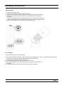
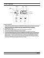
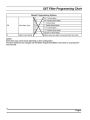
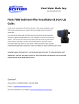
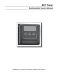
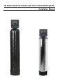
US Water Systems Prelude and Fusion Backwashing Filter Installation Manual Assembly Instructions Media Installation 1) 2) 3) 4) Remove the tank from carton. Verify the riser is still fully engaged in the Vortech plate. Place a piece of duct tape over the riser tube so no media enters the riser while filling. Make sure the riser is centered to facilitate the valve installation after installation of the media. 5) Use the Funnel provided, to pour the media into the tank. Pour it evenly around the hole to ensure it is well distributed in the tank and pour slow enough, to keep from plugging the hole. 6) When media is installed move tank side to side to settle the media. Valve Installation 1) Remove the tape from the riser and discard. 2) Fill the tank with water and allow the media to soak as long as possible prior to start up. This will dramatically reduce the rinse/flush time required to remove fines/debris from the filter and plumbing. 3) Lubricate the two o-rings with a light coat of Silicone. 4) Install the Upper Basket to the valve, twisting it to lock it in place. 5) Slip the Upper Basket over the Riser sliding it down into place and screw the valve on and tighten. 6) Follow the installation procedures in this manual and program accordingly. Page 1 Installation Instructions WATER PRESSURE: A minimum of 20 pounds of water pressure is required for regeneration valve to operate effectively. ELECTRICAL FACILITIES: An uninterrupted alternating current (A/C) supply is required. Note: Other voltages are available. Please make sure your voltage supply is compatible with your unit before installation. EXISTING PLUMBING: Condition of existing plumbing should be free from lime and iron buildup. Piping that is built up heavily with lime and/or iron should be replaced. If piping is clogged with iron, a separate iron filter unit should be installed. LOCATION OF FILTER AND DRAIN: The filter should be located close to a drain to prevent air breaks and back flow. BYPASS VALVES: Always provide for the installation of a by-pass valve if unit is not equipped with one. CAUTION: Water pressure is not to exceed 125 psi, water temperature is not to exceed 110°F, and the unit cannot be subjected to freezing conditions. Installation Instructions 1. Place the filter tank where you want to install the unit making sure the unit is level and on a firm base. 2. During cold weather, the installer should warm the valve to room temperature before operating. 3. All plumbing should be done in accordance with local plumbing codes. The pipe size for residential drain line should be a minimum of 1/2". Backwash flow rates in excess of 7 gpm or length in excess of 20’ require 3/4" drain line. Commercial drain lines should be the same size as the drain line flow control. 4. Refer to the dimensional drawing for cutting height of the distributor tube. If there is no dimensional drawing, cut the distributor tube flush with the top of the tank (typically pre-cut). 5. Lubricate the distributor o-ring seal and tank "o" ring seal. Place the main control valve on tank. Note: Only use silicone lubricant. 6. Solder joints near the drain must be done prior to connecting the Drain Line Flow Control fitting (DLFC). Leave at least 6" between the DLFC and solder joints when soldering pipes that are connected on the DLFC. Failure to do this could cause interior damage to the DLFC. 7. Teflon tape is the only sealant to be used on the drain fitting. 8. On units with a by-pass, place in by-pass position. Turn on the main water supply. Open a cold water tap nearby and let run a few minutes or until the system is free from foreign material (usually solder) that may have resulted from the installation. Once clean, close the water tap. 9. Slowly place the by-pass in service position and let water flow into the media tank. When water flow stops. 10. Plug unit into an electrical outlet. Note: All electrical connections must be connected according to local codes. (Be certain the outlet is uninterrupted). Page 2 Start-Up Instructions The water filter should be installed with the inlet, outlet, and drain connections made in accordance with the manufacturer's recommendations, and to meet applicable plumbing codes. 1. Push and hold the “extra cycle” button (far left button with triangle shaped arrows on the button). This button will advance the valve to the next cycle if it is pushed and released. 2. This will position the valve to backwash. You will see BW and four dashes. The four dashes will change to a time value that will start to count down. Once the time begins to count down. Slowly open the bypass valve to the service position. Ensure the drain line flow remains steady for 10 minutes or until the water runs clear (see above). 3. After the backwash cycle, the valve will move to the rapid rinse position. Check the drain line flow, and run for 5-10 minutes or until the water runs clear. 4. The filter is now installed. Proceed to programming. Page 3 Timer Features Parameter Display Data Display PM Indicator Error/ Information Icon Flow Indicator Service Icon x1000 Indicator Programming Icon Extra Cycle Button Up Button Down Button Features of the SXT: Power backup that continues to keep time and the passage of days for a minimum of 48 hours in the event of power failure. During a power outage, the control goes into a power-saving mode. It does not monitor water usage during a power failure, but it does store the days remaining at the time of power failure. Settings for both valve (basic system) and control type (method used to trigger a regeneration). Day-of-the-Week controls. While in service, the display alternates between time of day and days to regeneration. The Service Icon flashes if a backwash cycle has been queued. A backwash can be triggered immediately by pressing the Extra Cycle button for five seconds. The Parameter Display displays the current Cycle Step (BW, RR, etc) during backwash, and the data display counts down the time remaining for that cycle step. While the valve is transferring to a new cycle step, the display will flash. The parameter display will identify the destination cycle step (BW, RR, etc) and the data display will read "----". Once the valve reaches the cycle step, the display will stop flashing and the data display will change to the time remaining. During regeneration, the user can force the control to advance to the next cycle step immediately by pressing the extra cycle button. Page 4 Timer Features Setting the Time of Day 1. Press and hold either the Up or Down buttons until the programming icon replaces the service icon and the parameter display reads TD. 2. Adjust the displayed time with the Up and Down buttons. 3. When the desired time is set, press the Extra Cycle button to resume normal operation. The unit will also return to normal operation after 5 seconds if no buttons are pressed. Queueing a Backwash 1. 2. Press the Extra Cycle button. The service icon will flash to indicate that a backwash is queued. To cancel a queued backwash, press the Extra Cycle button. Backwashing Immediately Press and hold the Extra Cycle button for five seconds. Page 5 Timer Operation Time Clock Delayed Control A Time Clock Delayed Control regenerates the system on a timed interval. The control will initiate a backwash cycle at the programmed backwash time when the number of days since the last backwash equals the backwash day override value. Day of the Week Control This control regenerates the system on a weekly schedule. The schedule is defined in Master Programming by setting each day to either "off" or "on." The control will initiates a regeneration cycle on days that have been set to "on" at the specified regeneration time. Control Operation During Programming The control only enters the Program Mode with the valve in service. Control programming is stored in memory permanently, eliminating the need for battery backup power. Manually Initiating a Backwash 1. When timer is in service, press the Extra Cycle button for 5 seconds on the main screen. 2. The timer advances to Backwash Cycle Step #1 (backwash), and begins programmed time count down. 3. Press the Extra Cycle button once to advance valve to Regeneration Cycle Step #2 (brine rapid rinse). 4. Press the Extra Cycle button once more to advance the valve back to in service. 5. NOTE: A queued backwash can be initiated by pressing the Extra Cycle button. To clear a queued regeneration, press the Extra Cycle button again to cancel. If backwash occurs for any reason prior to the delayed backwash time, the manual backwash request shall be cleared. Page 6 Timer Operation Control Operation During A Power Failure The SXT includes integral power backup. In the event of power failure, the control shifts into a power-saving mode. The control stops monitoring water usage, and the display and motor shut down, but it continues to keep track of the time and day for a minimum of 48 hours. The system configuration settings are stored in a non-volatile memory and are stored indefinitely with or without line power. The Time of Day flashes when there has been a power failure. Press any button to stop the Time of Day from flashing. If power fails while the unit is in regeneration, the control will save the current valve position before it shuts down. When power is restored, the control will resume the regeneration cycle from the point where power failed. Note that if power fails during a regeneration cycle, the valve will remain in it's current position until power is restored. The valve system should include all required safety components to prevent overflows resulting from a power failure during regeneration. The control will not start a new backwash cycle without line power. Page 7 SXT Filter Programming Chart Master Programming Options Abbreviation Parameter Option Abbreviation GAL DF Display Format Ur . VT Valve Type dF2b Standard Downflow/Upflow Double Backwash Fltr Fd Number of Tanks Standard Downflow/Upflow Single Backwash Filter Upfiow Brine First Other Meter (Flow) Delayed Fl Meter (Flow) Immediate tc Time Clock dAY NT Liters Cubic Meters Othr Control Type Gallons Cu dF1b UFbF CT Options Day of Week 1 Single Tank System 2 Two Tank System Ul Tank 1 in Service U2 Tank 2 in Service TS Tank in Service C Unit Capacity Unit Capacity (Grains) H Feedwater Hardness Hardness of Inlet Water RS Reserve Selection Percentage Safety Factor rc Fixed Reserve Capacity Percentage of the system capacity to be used as a reserve SF Safety Factor RC Fixed Reserve Capacity DO Day Override 1-99 The system's day override setting RT Regen Time 2:00 The time of day the system will regenerate BW, BD, RR, BF Regen Cycle Step Times No The time duration for each regeneration step. Adjustable from OFF and 0-199 minutes. NOTE: If "Othr" is chosen under "Valve Type", then RI, R2, R3, etc, will be displayed instead D1, 02, D3, D4, D5, 06, & D7 Day of Week Settings Regeneration setting (On or OFF) for each day of the week on day-of-week systems CD Current Day The Current day of the week Fixed volume to be used as a reserve Changes Here CAUTION: Before entering Master Programming, please contact your local professional water dealer. Page 8 Page 9 Master Programming Mode When the Master Programming Mode is entered, all available option setting displays may be viewed and set as needed. Depending on current option settings, some parameters cannot be viewed or set. Use the previous chart to program your filter. You will use the highlighted values. Items not highlighted either do not require a change or do not appear in filter mode. Entering Master Programming Mode Set the Time Of Day display to 12:01 P.M. Press the “extra cycle”. Then press and hold the Up and Down buttons together until the programming icon replaces the service icon and the Display Format screen appears. The extra cycle button will serve as an “enter/save” button. The up and down arrows are used to change the value of each parameter and the extra cycle button saves the parameter changes and will move the control to the next programming parameter. Exiting Master Programming Mode Press the Extra Cycle button to accept the displayed settings and cycle to the next parameter. Press the Extra Cycle button at the last parameter to save all settings and return to normal operation. The control will automatically disregard any programming changes and return to normal operation if it is left in Master Programming mode for 5 minutes without any keypad input. Resets: Soft Reset: Press and hold the Extra Cycle and Down buttons for 25 seconds while in normal Service mode. This resets all parameters to the system default values, except the volume remaining in meter immediate or meter delayed systems and days since regeneration in the time clock system. Master Reset: Hold the Extra Cycle button while powering up the unit. This resets all of the parameters in the unit. Check and verify the choices selected in Master Programming Mode. Page 10 Master Programming Mode 1. Display Format (Display Code DF) This is the first screen that appears when entering Master Programming Mode. The Display Format setting specifies the unit of measure that will be used for volume and how the control will display the Time of Day. This option setting is identified by "DF" in the upper left hand corner of the screen. There are three possible settings: Display Format Setting Unit of Volume Time Display GAL U.S. Gallons 12-Hour AM/PM Ltr Liters 24-Hour Cu Cubic Meters 24-Hour 2. Valve Type (Display Code VT) Press the Extra Cycle button. Use this display to set the Valve Type. The Valve Type setting specifies the type of cycle that the valve follows during regeneration. Note that some valve types require that the valve be built with specific subcomponents. Ensure the valve is configured properly before changing the Valve Type setting. This option setting is identified by "VT" in the upper left hand corner of the screen. There are 5 possible settings: Abbreviation Parameter St1b Standard Downflow/Upflow, Single Backwash St2b Standard Downflow/Upflow, Double Backwash Fltr Filter UFbF Upflow Brine First Othr Other 3. Control Type (Display Code CT) Press the Extra Cycle button. Use this display to set the Control Type. This specifies how the control determines when to trigger a regeneration. For details on how the various options function, refer to the "Timer Operation" section of this service manual. This option setting is identified by "CT" in the upper left hand corner of the screen. There are four possible settings: Meter Delayed: Meter Immediate: Time Clock: Day of Week: Fd FI tc dAY Page 11 Master Programming Mode 4. Number of Tanks (Display Code NT) Press the Extra Cycle button. Use this display to set the Number of Tanks in your system. This option setting is identified by "NT" in the upper left hand corner of the screen. There are two possible settings: Single Tank System: Two-Tank System: 1 2 5. Tank in Service (Display Code TS) Press the Extra Cycle button. Use this display to set whether tank one or tank two is in service. This option setting is identified by "TS" in the upper left hand corner of the screen. This parameter is only available if the number of tanks has been set to 2. There are two possible settings: Tank One in Service: U1 Tank Two in Service: U2 6. Unit Capacity (Display Code C) Press the Extra Cycle button. Use this display to set the Unit Capacity. This setting specifies the treatment capacity of the system media. Enter the capacity of the media bed in grains of hardness when configuring a softener system, and in the desired volume capacity when configuring a filter system. This option setting is identified by "C" in the upper left hand corner of the screen. The Unit Capacity parameter is only available if the control type has been set to one of the metered options. Use the Up and Down buttons to adjust the value as needed. Range: 1-999,990 grain capacity 7. Feedwater Hardness (Display Code H) Press the Extra Cycle button. Use this display to set the Feedwater Hardness. Enter the feedwater hardness in grains per unit volume for softener systems, or 1 for filter systems. This option setting is identified by "H" in the upper left hand corner of the screen. The feedwater hardness parameter is only available if the control type has been set to one of the metered options. Use the Up and Down buttons to adjust the value as needed. Range: 4-199 hardness Page 12 Master Programming Mode 8. Reserve Selection (Display Code RS) Press the Extra Cycle button. Use this display to set the Safety Factor. Use this display to select the type of reserve to be used in your system. This setting is identified by "RS" in the upper left-hand corner of the screen. The reserve selection parameter is only available if the control type has been set to one of the metered options. There are two possible settings. FS rc Safety Fector Fixed Reserve Capacity 9. Safety Factor (Display Code SF) Press the Extra Cycle button. Use this display to set the Safety Factor. This setting specifies what percentage of the system capacity will be held as a reserve. Since this value is expressed as a percentage, any change to the unit capacity or feedwater hardness that changes the calculated system capacity will result in a corresponding change to the reserve volume.This option setting is identified by "SF" in the upper left hand corner of the screen. Use the Up and Down buttons to adjust the value from 0 to 50% as needed. Range: 0-50% 10. Fixed Reserve Capacity (Display Code RC) Press the Extra Cycle button. Use this display to set the Reserve Capacity. This setting specifies a fixed volume that will be held as a reserve. The reserve capacity cannot be set to a value greater than one-half of the calculated system capacity. The reserve capacity is a fixed volume and does not change if the unit capacity or feedwater hardness are changed. This option setting is identified by "RC" in the upper left-hand corner of the screen. Use the Up and Down buttons to adjust the value as needed. Range: 0- half the calculated capacity CAUTION: Before entering Master Programming, please contact your local professional water dealer. Page 13 Master Programming Mode 11. Day Override (Display Code DO) Press the Extra Cycle button. Use this display to set the Day Override. This setting specifies the maximum number of days between regeneration cycles. If the system is set to a timer-type control, the day override setting determines how often the system will regenerate. A metered system will regenerate regardless of usage if the days since last regeneration cycle equal the day override setting. Setting the day override value to "OFF" disables this function. This option setting is identified by "DO" in the upper left hand corner of the screen. Use the Up and Down buttons to adjust the value as needed. Range: Off-99 days 12. Regeneration Time Press the Extra Cycle button. Use this display to set the Regeneration Time. This setting specifies the time of day the control will initiate a delayed, manually queued, or day override triggered regeneration. This option setting is identified by "RT" in the upper left hand corner of the screen. Use the Up and Down buttons to adjust the value as needed. 13. Regeneration Cycle Step Times Press the Extra Cycle button. Use this display to set the Regeneration Cycle Step Times. The different regeneration cycles are listed in sequence based on the valve type selected for the system, and are identified by an abbreviation in the upper left-hand corner of the screen. The abbreviations used are listed below. If the system has been configured with the "OTHER" valve type, the regeneration cycles will be identified as R1, R2, R3, R4, R5, and R6. Each cycle step time can be set from 0 to 199 minutes, or "OFF." Setting a cycle step to "OFF" will disable all of the following steps. Setting a cycle step time to 0 will cause the control to skip that step during regeneration, but keeps the following steps available. Use the Up and Down buttons to adjust the value as needed. Press the Extra Cycle button to accept the current setting and move to the next parameter. Cycle Step Abbreviation BD Brine Draw BF Brine Fill BW Backwash RR Rapid Rinse SV Service Range: 0-199 minutes CAUTION: Before entering Master Programming, please contact your local professional water dealer. Page 14 Master Programming Mode 14. Day of Week Settings Press the Extra Cycle button. Use this display to set the regeneration schedule for a system configured as a Day of Week control. The different days of the week are identified as D1, D2, D3, D4, D5, D6, and D7 in the upper lefthand corner of the display. Set the value to "ON" to schedule a regeneration or "OFF" to skip regeneration for each day. Use the Up and Down buttons to adjust the setting as needed. Press the Extra Cycle button to accept the setting and move to the next day. Note that the control requires at least one day to be set to "ON." If all 7 days are set to "OFF", the unit will return to Day One until one or more days are set to "ON." 15. Current Day (Display Code CD) Press the Extra Cycle button. Use this display to set the current day on systems that have been configured as Day of Week controls. This setting is identified by "CD" in the upper left-hand corner of the screen. Use the Up and Down buttons to select from Day 1 through Day 7. 16. Flow Meter Type (Display Code FM) Press the Extra Cycle button. Use this display to set the type of flow meter connected to the control. This option setting is identified by "FM" in the upper left-hand corner of the screen. Use the Up and Down buttons to select one of the 7 available settings. t0.7 P0.7 t1.0 P1.0 t1.5 P1.5 GEn Fleck 3/4" Turbine Meter Fleck 3/4" Paddle Wheel Meter Fleck 1" Turbine Meter Fleck 1" Paddle Wheel Meter Fleck 1 1/2" Turbine Meter Fleck 1 1/2" Paddle Wheel Meter Generic/Other Meter CAUTION: Before entering Master Programming, please contact your local professional water dealer. Page 15 Master Programming Mode 17. Meter Pulse Setting (Display Code K) Press the Extra Cycle button. Use this display to specify the meter pulse setting for a non-standard flow meter. This option setting is identified by "K" in the upper left-hand corner of the screen. Use the Up and Down buttons to enter the meter constant in pulses per unit volume. 18. Press the Extra Cycle button to save all settings and exit Master Programming Mode. Page 16 User Programming Mode User Programming Mode Options Abbreviation Parameter Description DO Day Override The timer's day override setting RT Regeneration Time The time of day that the system will regenerate (meter delayed, timeclock, and day-ofweek systems) H Feed Water Hardness The hardness of the inlet water - used to calculate system capacity for metered systems RC Reserve Capacity The fixed reserve capacity CD Current Day The current day of week NOTES: Some items may not be shown depending on timer configuration. The timer will discard any changes and exit User Mode if any button is not pressed for sixty seconds. User Programming Mode Steps 1. 2. Press the Up and Down buttons for five seconds while in service, and the time of day is NOT set to 12:01 PM. Use this display to adjust the Day Override. This option setting is identified by "DO" in the upper left hand corner of the screen. 3. Press the Extra Cycle button. Use this display to adjust the Regeneration Time. This option setting is identified by "RT" in the upper left hand corner of the screen. 4. Press the Extra Cycle button. Use this display to adjust the Feed Water Hardness. This option setting is identified by "FH" in the upper left hand corner of the screen. Page 17 Notes Page 18 Powerhead Assembly 1 2 0 9 1 0 1 1 1 2 1 6 17 16 1 5 1 3 14 3 1 6 2 1 6 1 8 1 1 9 1 6 4 5 6 7 8 Page 19 Powerhead Assembly Item No. 1 ........ 2 ......... 3 ......... 4 ......... 5 ......... 6 ......... 7 ......... 8 ......... 9 ......... 10 ....... 11 ...... 12 ....... 13 ....... 14 ....... 15 ....... 16 ....... 17 ....... 18 ....... 19 ....... 20 ....... Quantity 1 ............... 2................ 2................ 1 ............... 1 ............... 1 ............... 1 ............... 1 ............... 1 ............... 1 ............... 1 ............... 1 ............... 1 ............... 2................ 1 ............... 6................ 1 ............... 1 ............... 1 ............... 2................ Part No. 40269.......................... 10218.......................... 17876.......................... 40326.......................... 42196.......................... 42635-01 .................... 42637.......................... 18260.......................... 19927.......................... 18211-01 .................... 18228.......................... 18202.......................... 40251.......................... 13602.......................... 18655.......................... 13296.......................... 13363.......................... 13547.......................... 18259-02 .................... 18261.......................... Description PLATE, FRONT SWITCH, MICRO SCREW, PHIL PAN, 4-40 X 1-1/8" LABEL, COVER-UP, PROFLOSE CIRCUIT BOARD, SXT CONTROL FRONT COVER, SXT, SQUARE, BLACK LABEL, DISPLAY, SXT COVER, FRONT CAM, RAYNE, D/F, SE GEAR MAIN, DOWNFLOW, MACHD CAM, BRINE VALVE BACK PLATE MOTOR, 24V - 50/60HZ SCREW, PHIL RD HD, 6-32 X 5/16 PIN, ROLL, 3/32 X 1/2 SCREW, HEXWASHER, 6-20 X 1/2 WASHER, PLAIN, .145 ID SS STRAIN RELIEF, ROUND CORD COVER, BACK, BLACK SCREW, HEXWASHER HEAD, #10-24 X .81 For Service Assembly Numbers, See the Back of this Manual Page 20 Control Valve Assembly Page 21 Control Valve Assembly ItemNo. Quantity 1 .................... 1 .............. 2 ..................... 1 .............. 3 ..................... 4 ............... 4 ..................... 5 ............... 5 ..................... 1 .............. 6 ..................... 1 .............. 7 ..................... 1 .............. 8 ..................... 3 ............... 9 ..................... 1 .............. 10 ................... 1 .............. 11 .................. 1 .............. 12 ................... 1 .............. 13 ................... 1 .............. 14 ................... 2 ............... 15 ................... 1 .............. 16 ................... 1 .............. 17 ................... 1 .............. 18 ................... 1 .............. 19 ................... 1 .............. 20 ................... 1 .............. 21 .................. 1 .............. 22 ................... 1 .............. 23 ................... 1 .............. 24 ................... 1 .............. 25 ................... 2 ............... 26 ................... 1 .............. 27 ................... 2 ............... 28 ................... 1 .............. 29 ................... 1 .............. 30 ................... 1 .............. 31 .................. 1 .............. 32 ................... 1 .............. 33 ................... 1 .............. 34 ................... 2 ............... 35 ................... 1 .............. 36 ................... 1 .............. 37 ................... 1 .............. 38 ................... 1 .............. 39 ................... 1 .............. ....................... 1 40.................... ................... 1 .............. ....................... 1....................... .................... 1 .................... 41 .................. 1 .............. Filter Only (Not Shown) ....................... 1....................... .................... 1....................... .................... 1 .................... Part No. Description 18815 .......................... Valve Body Assy, 5000, 1" Dist Down Flow 18264 .......................... Spacer, End, 5000 14241 .......................... Spacer, 5600 13242 .......................... Seal, 5600 18265 .......................... Piston, 5000, Downflow 14309 .......................... Retainer, Piston Rod 18268 .......................... End Plug Assy 18261 .......................... Screw, Hex Wsh Hd, 10-24 x 13/16 18267 .......................... Rod, Piston 17978 .......................... Brine Valve Stem, 5600, Plastic 18755 .......................... O-ring, Brine Seat 13167 .......................... Spacer, Brine Valve 12550 .......................... Quad Ring, -009 13302 .......................... O Ring, -014 13165 .......................... Cap, Brine Valve 11973 .......................... Spring, Brine Valve 16098 .......................... Washer, Nylon, Brine 11981-01 ..................... Ring, Retaining 11183 .......................... O-Ring, -017 Flow Washer (specify size) 11385-01 ..................... Housing, Flow Control, Plastic 18312 .......................... Retainer, Drain 13304 .......................... O-Ring, -121 18303 .......................... O-Ring, -336 10141 .......................... O-Ring, -010 18276 .......................... Plug, Injector 13771 .......................... O-Ring, -012 18275-X ....................... Throat, Injector (specify size) 000, 00, 0, 1, 2, 3 18274-X ....................... Nozzle, Injector (specify size) 000, 00, 0, 1, 2, 3 18273 .......................... Vortex, Generator 18271 .......................... Screen, Injector, 5000 18301 .......................... Seal, Injector, 4200 18277 .......................... Cap, Injector 18262 .......................... Screw, Hex Wsh Hd, 10-24 x 1 12977 .......................... O-Ring, -015 13245 .......................... Retainer, BLFC Flow Washer (specify size) 13244 .......................... Adapter, BLFC 13308 .......................... Fitting, Hose Barb, Black 12338 .......................... Fitting, Elbow, 90 Deg, 1/2 Black 18280 .......................... Collector, Top, 1" x .011 Gray Bayonet 18280-01 ..................... Collector, Top, 1" x .020, White Wide Slot, Bayonet 18280-02 ..................... Collector, Top, 1" x .008, Red Narow Slot, Bayonet 14613 .......................... Flow Straightener 13857 .......................... Injector Plug Assy, w/O-ring 13918 .......................... Plug, BLFC Module 18276-01 ..................... INJECTOR ASSY,PLUG,W/O-RINGS OPTION - Adapter Coupling Day Clock Only 45 ................... 2 ............... 46 ................... 4 ............... 47 ................... 2 ............... 48 ................... 2 ............... 19228 .......................... Coupling, Adapter 13305 .......................... O-Ring, -119 13255 .......................... Clip, Mounting 13314 .......................... Screw, Slot Ind Hex, 18-8 x .60 For Service Assembly Numbers, See the Back of this Manual Page 22 3/4" Turbine Meter Assembly Item No. 1 ........ 2 ........ 3 ........ 4 ........ 5 ........ ..................... Quantity 2 ............. 2 ............. 1 ............. 4 ............. 1 ............. 1 ............ Part No. Description 13314 ....................... Screw, Hex Washer, 8-18 x 5/8 19569 ....................... Clip, Flow Meter 19797 ....................... Meter Body Assembly, 3/4" Turbine 13305 ....................... O-ring, 119 19791-01 .................. Harness Assembly, Flow Meter 19791-02 .................. Meter Cable Assy, 35" Not Shown: 1 ............. 14613 ....................... Flow Straightener For Service Assembly Numbers, See the Back of this Manual Page 23 Bypass Valve Assembly (Plastic) Item No. 1 ....... 2 ....... 3 ....... 4A ..... Quantity 2 ............ 2 ............ 2 ............ 1 ........... .......................................... 413 ... 1 ........... .......................................... .......................................... .......................................... .......................................... .......................................... .......................................... .......................................... .......................................... Part No. Description 13305 ...................... O-ring, -119 13255 ...................... Clip, Mounting 13314 ...................... Screw, Slot Ind Hex, 8-18 x .60 18706 ...................... Yoke, 1", NPT, Plastic 18706-02 ................. Yoke, 3/4", NPT, Plastic 13708-40 ................. Yoke, 1", Sweat 13708-45 ................. Yoke, 3/4", Sweat 19275 ...................... Yoke, Angle 90 Deg, 3/4", NPT 19275-45 ................. Yoke, Angle 90 Deg, 3/4" Sweat 19620-01 ................. Yoke Assy, 3/4", R/Angle, 90 Deg w/O-rings, Clips & screws 40636 ...................... Yoke, 1 1/4", NPT 40636-49 ................. Yoke, 1 1/4", Sweat 41027-01 ................. Yoke, 3/4", NPT, Cast, Machd 41026-01 ................. Yoke, 1", NPT, Cast, Machd, SS For Service Assembly Numbers, See the Back of this Manual Page 24 Bypass Valve Assembly (Metal) Item No. Quantity 1 ........... 1 ............. Part No. Description 40614 ...................... By-Pass Body, 3/4" 40634 ...................... By-Pass Body, 1", SS ............................................ 2 ........... 1 ............. 14105 ...................... Seal, By-Pass, 560CD 3 ........... 1 ............. 11972 ...................... Plug, Bypass, w/Wax 4 ........... 1 ............. 11978 ...................... Plate, Bypass, Top 5 ........... 1 ............. 13604-01 ................. Label, Bypass, Standard Mount 6 ........... 8 ............. 15727 ...................... Screw, Hex Wsh Hd, 10-24 x 1/2 7 ........... 1 ............. 11986 ...................... Plate, Bypass, Bottom 8 ........... 1 ............. 11979 ...................... Lever, Bypass 9 ........... 1 ............. 11989 ...................... Screw, Sltd Indent, 1/4 - 14 x 1 1/2 10 ......... 1 ............. 60040SS .................Bypass Valve, 5600, 3/4" NPT Blk Grip Lever, Stainless Steel ............................................ 60041SS .......... Bypass Valve, 5600, 1" NPT Blk Grip Lever, ........................................................................... Stainless Steel For Service Assembly Numbers, See the Back of this Manual Page 25 Troubleshooting Problem Cause Correction 1. Water conditioner fails to backwash. A. Electrical service to unit has been interrupted A. Assure permanent electrical service (check fuse, plug, pull chain, or switch) B. Timer is defective. B. Replace timer. C. Power failure. C. Reset time of day. B. Excessive water in brine tank. B. See problem 7. A. Iron buildup in line to water conditioner. A. Clean line to water conditioner. B. Iron buildup in water conditioner. B. Clean control and add mineral cleaner to mineral bed. Increase frequency of regeneration. C. Inlet of control plugged due to foreign material broken loose from pipes by recent work done on plumbing system. C. Remove piston and clean control. A. Air in water system. Internal Failure A. Assure that well system has proper air eliminator control. Check for dry well condition. Check distributor. B. Improperly sized drain line flow control. B. Check for proper drain rate. 4. Contaminant in conditioned water. A. Fouled mineral bed. A. Check backwash, brine draw, and brine tank fill. Increase frequency of regeneration. Increase backwash time. 5. Control cycles continuously. A. Misadjusted, broken, or shorted A. Determine if switch or timer is switch. faulty and replace it, or replace complete power head. 6. Drain flows continuously. A. Valve is not programming correctly. 2. Loss of water pressure. 3. Loss of mineral through drain line. B. Foreign material in control. A. Check timer program and positioning of control. Replace power head assembly if not positioning properly. B. Remove power head assembly and C. Internal control leak. inspect bore. Remove foreign material and check control in various regeneration positions. C. Replace seals and piston assembly. Page 26 Troubleshooting Error Codes Note: Error codes appear on the In Service display. Error Code Probable Cause Recover and Resetting [Err 0] Drive motor is stalled Unplug the unit from the power source [Err 1] Drive motor is running continuously When power is restored to the unit, the Err _ display code clears. If the condition causing the error has not been resolved the Err _ code reappears in the four digit display. Do not attempt to troubleshoot this problem any further. [Err 2] There have been more than 99 days since the last Regeneration. If the Day of the Week mode of regeneration is selected and days since last regeneration exceeds 7 days. Regeneration must occur for the unit to recover, the display to clear and the valve to function normally. [ 7 - - 5 ]: There have been more than 7 days since the last regeneration. All individual settings (d1, d2, d3, d4, d5, d6, d7) are set to 0. [Err 3] Control board memory failure. [ 7 - - 5 ]: To recover from [Err2], the user must initiate a regeneration or set at least one individual day to 1. Perform a Master Reset. If the error returns, do not attempt to troubleshoot this problem any further. Error Display Example NOTE: Unit will !ash when an error exists. Page 27 Dimensional Drawing Page 28 ORANGE N.C. BLACK N.O. SW 1 SW2 HCAM T1 VDM BLUE BLUE WT/BLK YELLOW SCAM GREEN RED P1 METER -+ S BLACK YELLOW WT/BLK BLUE PWRV D O N N N.O. - H WHITE PURPLE H ORANGE S P2 BLACK H/S C C CB1 50/60 HZ N.C. N.O. BLACK PURPLE Wiring Diagram BLUE WHITE BLACK (BROWN) WHITE (BLUE) TM CB1 - SXT Timer T1 - 24V Transformer TM - 3/4" Turbine Flow Meter (Optional) VDM - Valve Drive Motor SW1 - Valve Homing Swith SW2 - Valve Step Switch HCAM - Valve Homing SCAM - Valve Step Page 29