1
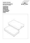
Installation information
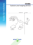
METTLER TOLEDO MultiRange
Table and stand scales
KA3s/KA6s
KA15s/KA32s
KB60/KCC150/KCC300
www.mt.com/support
Table and stand scales
Contents
Contents
Page
1
Safety instructions .......................................................................
4
2
2.1
2.2
2.3
Installation..................................................................................
Preparatory work ..........................................................................
Setting up and levelling .................................................................
Installing connection cable ............................................................
6
6
6
7
3
3.1
3.2
Configuration possibilities ...........................................................
General information ......................................................................
Configuration data ........................................................................
8
8
9
4
4.1
4.2
4.3
Planning assemblies ...................................................................
Notes on planning ........................................................................
Preload range ..............................................................................
Mounting possibilities ...................................................................
11
11
11
12
5
Dimensions ................................................................................. 15
Installation information 22007224A 07/11
3
Safety instructions
1
Table and stand scales
Safety instructions
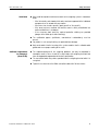
▲ The K line weighing platforms are approved for operation in Zone 2 (gases) and
Zone 22 (dusts) hazardous areas. There is an increased risk of injury and
damage when the weighing platforms are used in a hazardous area! Special
care must be taken when working in such hazardous areas. The rules for
behaviour are based on the concept of "Safe Distribution" established by
METTLER TOLEDO.
▲ Any protective foils present in the hazardous area, e.g. on the load plate, must
always be removed.
Competence
▲ The K line weighing platforms may only be installed, maintained and repaired by
authorised METTLER TOLEDO service personnel.
Ex approval
▲ No modifications may be made to the device and no repair work may be
performed on the modules. Any weighing cells or system modules that are used
must comply with the specifications contained in the installation instructions.
Non-compliant equipment jeopardises the intrinsic safety of the system, cancels
the Ex approval and renders any warranty or product liability claims null and
void.
▲ The safety of the weighing system is only guaranteed when the weighing system
is operated, installed and maintained in accordance with the respective
instructions.
▲ Also observe the following:
– The regulations and standards in the respective country
– The statutory requirement for electrical equipment installed in hazardous areas
in the respective country
– All instructions related to safety issued by the owner
▲ The explosion-protected weighing system must be checked to ensure compliance
with the requirements for safety before being put into service for the first time,
following any service work and at least every 3 years.
Operation
▲ Prevent the build-up of static electricity. Always wear suitable working clothes
when operating or performing service work in a hazardous area.
▲ Do not use protective coverings for the devices.
▲ Avoid damage to the system components.
4
Installation information 22007224A 07/11
Safety instructions
Table and stand scales
Installation
▲ Only install and perform maintenance work on the weighing system in hazardous
areas,
– if the intrinsically safe characteristic values and zone approval of the individual
components are in accord with one another
– if the owner has issued a permit ("spark permit" or "fire permit")
– if the area has been rendered safe and the owner's safety co-ordinator has
confirmed that there is no danger
– if the necessary tools and any required protective clothing are provided
(danger of the build-up of static electricity)
▲ The certification papers (certificates, manufacturer’s declarations) must be
present.
▲ Lay cables in such a way that they are protected from damage.
▲ Only route cables into the housing of the system modules via the suitable cable
gland and ensure proper seating of the seals.
Additional requirements
for Category 3
(Zones 2/22)
▲ The explosion-protected K line weighing platforms can only be operated in
hazardous areas in Zones 2 and 22 in conjunction with weighing terminals that
have the appropriate approval and interface specification.
▲ The connection cable may not be separated from the weighing terminal while it is
energised.
▲ Tighten the knurled nut of the IDNet connection cable with 10 Nm of force.
Installation information 22007224A 07/11
5
Installation
2
Table and stand scales
Installation
2.1
2.1.1
Preparatory work
Selecting installation location
▲ The foundation at the installation location must be capable of safely support the
weight of the weighing platform at its support points when it carries the
maximum load. At the same time, it should be so stable that no vibrations occur
during weighing operations. These requirements also apply when the weighing
platform is integrated in conveying systems and the like.
▲ Ensure that there are no vibrations from machines near the installation site.
▲ Ensure that there are no drafts at the installation site.
2.1.2
Ambient conditions
• Use powder-coated/enamelled weighing platforms only in a dry environment.
• In a damp environment, in wet operation or when working with chemicals: Use
stainless-steel weighing platforms.
2.1.3
Accessories
➜ Completely unpack the accessories provided with the weighing platform.
– 1 Identcard
– 1 Set of signs for selectable configurations
2.2
2.2.1
Setting up and levelling
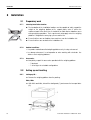
Setting up KA...
➜ Remove the weighing platform from the packing.
KA3s, KA6s
➜ With KA3s and KA6s, take off the draft guard (1) and remove the transport locks
(2).
6
Installation information 22007224A 07/11
Installation
Table and stand scales
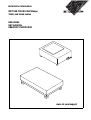
2.2.2
Setting up KB...
1. Lift the weighing platform out of the transport packing and set it down at the
installation location.
2. Remove the 4 corner padding pieces between the load plate and the frame.
3. Lift off the load plate and remove the 4 pieces of cardboard.
4. Mount the load plate again.
2.2.3
Setting up KCC...
1. Lift the weighing platform out of the transport packing and set it down at the
installation location.
2. Remove the 4 corner padding pieces between the load plate and the frame.
3. Remove the load plate by lifting the two side handles vertically (1.) and pivoting
outward (2.).
4. Remove the 4 pieces of cardboard.
5. Remount the load plate by swinging the handles inward (3.) and reengaging in
initial position (4.), i.e. the handles must be in the bottom position and vertical.
When the handles are correctly engaged, it should not be possible to lift off the load
plate.
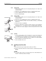
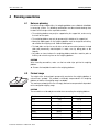
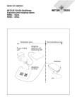
2.2.4
Levelling
1. Level the weighing platform with the 4 foot bolts (1) using the level indicator (2):
The air bubble of the level indicator must come to rest within the ring marking.
2. Ensure even contact of the foot bolts. Check the stability of the weighing platform
by pressing down on or rocking it at the corners.
3. Lock the foot bolts with the nuts.
2
1
2.3
Installing connection cable
Note
The connection cable may be lengthened to a maximum of 100 m.
➜ Route the connection cable to the terminal so that it is protected from possible
damage.
CAUTION
➜ If the cable is laid in a pipe, ensure that the pipe is of a sufficient diameter or is
slit open. The cable may not be cut through.
Installation information 22007224A 07/11
7
Configuration possibilities
3
Table and stand scales
Configuration possibilities
3.1
3.1.1
General information
MultiInterval
• MultiInterval precision means automatic switchover of the numerical increment
(readability) in dependence on the applied load.
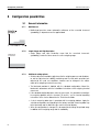
3.1.2
• Single Range and High Resolution mean that the numerical increments
(readability) remain the same across the entire weighing range.
Numerical
increment
0 Load weighed
Single Range and High Resolution
max.
3.1.3
Additional setting options
• All other adjustment variables (adjustment to the weighing process and vibrations,
as well as adjustment of stability monitoring and the zero point correction) are
adjusted to the usual user conditions, however can be changed in the master
mode of the weighing terminal if necessary.
• The Identcard provided is labelled with the standard configuration. Mount the
Identcard in accordance with the installation instructions of the weighing terminal
concerned.
• If the standard configuration does not meet your needs, it is possible to reconfigure
the weighing platform with the terminal. To do this, see the terminal operating
instructions or the Service Manual for the TBrick Service Mode.
• A set of measuring data signs is provided with the weighing platform. Apply the
selected configuration corresponding to the factory-mounted measuring data sign
to the Identcard, and the Max-Min sign near the terminal display.
• When the configuration is changed, it is also possible to change the preload range
in addition to the weighing range and the readability.
8
Installation information 22007224A 07/11
Configuration possibilities
Table and stand scales
3.2
3.2.1
Configuration data
Configuration data for KA3s/KA6s, factory setting
Standard configuration
KA3s
KA6s
Maximum load
3 kg
6 kg
Readability
0 ... 3 kg
Tare range, subtractive
3 kg
6 kg
± 60 g
± 120 g
–60 g ... +540 g
–120 g ... +1080 g
II
0.0001 kg
0.0005 kg
0 °C ... +40 °C
II
0.0002 kg
0.01 kg
0 °C ... +40 °C
Preload range
Zero-set range ±2 %
Zero-set range
–2 % ... +18 %
Calibration data as per
OIML
Calibration class
Calibration value
Minimum load
Temperature range
3.2.2
0.01 g
0 ... 6 kg
0.2 g
Configuration data for KA15s/KA32s, factory setting
Standard configuration
KA15s
KA32s
Maximum load
15 kg
32 kg
Readability
0 ... 15 kg
Tare range, subtractive
15 kg
32 kg
Preload range
Zero-set range
Zero-set range (typ.)
± 0.3 kg
6.0 kg
± 0.64 kg
3.0 kg
Calibration data as per
OIML
Calibration class
Calibration value
Minimum load
Temperature range
II
0.001 kg
0.005 kg
0 °C ... +40 °C
II
0.001 kg
0.005 kg
0 °C ... +40 °C
Installation information 22007224A 07/11
0.1 g
0 ... 32 kg
0.1 g
9
Configuration possibilities
3.2.3
Table and stand scales
Configuration data for KB.../KCC..., factory setting
Standard configuration
KB60
KCC150
KCC300
Maximum load
60 kg
150 kg
300 kg
Readability
0 ... 60 kg
Tare range, subtractive
60 kg
150 kg
300 kg
Preload range
Zero-set range
Zero-set range (typ.)
± 1.2 kg
25 kg
± 3 kg
64 kg
± 6 kg
120 kg
Calibration data as per
OIML
Calibration class
Calibration value
Minimum load
Temperature range
II
0.01 kg
0.05 kg
0 °C ... +40 °C
II
0.01 kg
0.05 kg
0 °C ... +40 °C
III
0.05 kg
1.0 kg
–10 °C ... +40 °C
10
0.001 kg
0 ... 150 kg
0.001 kg
0 ... 300 kg
0.002 kg
Installation information 22007224A 07/11
Planning assemblies
Table and stand scales
4
Planning assemblies
4.1
Notes on planning
Due to their design characteristics, the weighing platforms are suitable for installation
in conveying systems. The following specifications and dimensional drawings form
the basis for the design of the required assemblies.
• The weighing platform may only be supported by the support feet, and never by
the frame or lever parts.
• The weighing platform may only be permanently installed on the support feet.
• Moving or rotating parts on the weighing platform must be designed so that they
do not affect the weighing result. Balance rotating parts.
• The load plate must be free on all sides so that not connection between the load
plate and permanently mounted parts is made, even by falling parts or dirt
deposits.
• Lay cables or hoses between the weighing platform and other machine parts so
that they do not exert any force on the weighing platform.
CAUTION
When mounting assemblies, make sure that no metal chips get into the weighing
platform.
➜ Remove the load plate to machine the weighing platform.
4.2
Preload range
The weight of the structural parts permanently mounted on the weighing platform is
referred to as "preload". The preload is electrically compensated in the weighing
platform so that the full weighing range is available.
The maximum preload (or the zero-set range) that can be compensated is dependent
on the configured weighing range.
CAUTION
The assemblies must already be mounted when connecting the weighing platform.
Model
Weighing range
KA3s
3 kg
3.2 kg
KA6s
6 kg
1.6 kg
KA15s
15 kg
6 kg
KA32s
32 kg
3 kg
KB60
60 kg
25 kg
KCC150
150 kg
64 kg
KCC300
300 kg
120 kg
Installation information 22007224A 07/11
Max. preload
11
Planning assemblies
Table and stand scales
4.3
Mounting possibilities
Mounting possibilities for KA3s/KA6s
No assemblies can be mounted to the load plate on the KA3s and KA6s weighing
platforms.
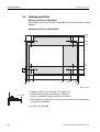
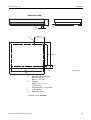
Mounting possibilities for KA15s/KA32s
280
275
240
225
55
40
5
0
5 20
40
270
310
0
345
350
Dim. in mm
• Bridge assemblies can be mounted in the shaded areas.
max. 6 mm
• Recommended mounting type: Bolting on, welding on.
Remove the load plate and drill through for this purpose.
• Mounting parts (e.g. bolts and nuts) may extend a maximum of 6 mm beyond the
underside of the load plate.
Technical version: 08/2000
12
Installation information 22007224A 07/11
Planning assemblies
Table and stand scales
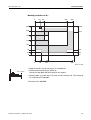
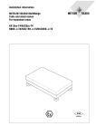
Mounting possibilities for KB...
0
83 125
420
500
400
400
340
324
285
220
165
76
76
35
0
35
0
0
86
166
500
Dim. in mm
• Bridge assemblies can be mounted in the shaded areas.
max. 10 mm
• Recommended mounting type: Bolting on.
Remove the load plate and drill through for this purpose.
• Mounting parts (e.g. bolts and nuts) may extend a maximum of 10 mm beyond
the underside of the load plate.
Technical version: 08/2000
Installation information 22007224A 07/11
13
Planning assemblies
Table and stand scales
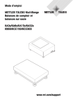
Mounting possibilities for KCC...
0
180
525
620
800
600
600
505
460
255
210
140
0
0
Dim. in mm
0
580
700
800
650
• Bridge assemblies can be mounted in the shaded areas.
max. 10 mm
• Recommended mounting type: Bolting on.
Remove the load plate and drill through for this purpose.
• Mounting parts (e.g. bolts and nuts) may extend a maximum of 10 mm beyond
the underside of the load plate.
Technical version: 08/2000
14
Installation information 22007224A 07/11
Dimensions
Table and stand scales
5
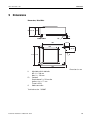
Dimensions
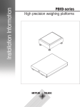
Dimensions, KA3s/KA6s
H
H – 6 103
16
D
FS
302
19.25
200
85.75
275
200
232
C
345
Dimensions in mm
H
FS
C
Adjustable with 4 foot bolts
Min. H = 130 mm
Max. H = 140 mm
Foot bolt
Required area D = 35 mm dia.
Spanner size = 17 mm
Thread = M10
Cable connection
Technical version: 12/2007
Installation information 22007224A 07/11
15
Dimensions
Table and stand scales
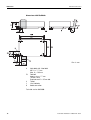
Dimensions of KA15s/KA32s
Dim. in mm
H
FS
S
L
C
Adjustable with 4 foot bolts
Min. H = 117 mm
Max. H = 130 mm
Foot bolt
Spanner size = 17 mm
Thread = M10
Required area D = 35 mm dia.
Tripod
Level indicator
Cable connection
Technical version: 08/2000
16
Installation information 22007224A 07/11
Dimensions
Table and stand scales
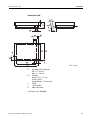
Dimensions of KB...
Dim. in mm
H
FS
S
L
C
Adjustable with 4 foot bolts
Min. H = 123 mm
Max. H = 148 mm
Foot bolt
Spanner size = 17 mm
Thread = M10
Required area D = 35 mm dia.
Tripod
Level indicator
Cable connection
Technical version: 08/2000
Installation information 22007224A 07/11
17
Dimensions
Table and stand scales
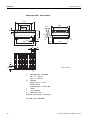
Dimensions of KB... roller conveyor
455
325
195
65
406
344
31.5
Ø 40
FS
H
75°
D
S
L
65
431
506
85
337
33
C
108±15
Dim. in mm
L
H
Adjustable with 4 foot bolts
Min. H = 170 mm
Max. H = 195 mm
FS
Foot bolt
Spanner size = 17 mm
Thread = M10
Required area D = 35 mm dia.
S
Tripod
L
Level indicator
C
Cable connection
Weight of roller conveyor = 9.0 kg net
Technical version: 08/2000
18
Installation information 22007224A 07/11
Dimensions
Table and stand scales
Dimensions of KCC...
H
FS
D
L
C
230±15
C
503 600
125
724
L
Dim. in mm
800
H
FS
L
C
Adjustable with 4 foot bolts
Min. H = 130 mm
Max. H = 155 mm
Foot bolt
Spanner size = 17 mm
Thread = M10
Required area D = 35 mm dia.
Level indicator
Cable connection
Technical version: 08/2000
Installation information 22007224A 07/11
19
Dimensions
Table and stand scales
Dimensions of KCC... roller conveyor
752
564
376
188
606
531
Ø 50
H
D
FS
C
724
503
806
233±15
C
L
Dim. in mm
H
Adjustable with 4 foot bolts
Min. H = 185 mm
Max. H = 210 mm
FS
Foot bolt
Spanner size = 17 mm
Thread = M10
Required area D = 35 mm dia.
L
Level indicator
C
Cable
Weight of roller conveyor = 22.0 kg net
Technical version: 08/2000
20
Installation information 22007224A 07/11
*22007224A*
22007224A
Subject to technical changes
© Mettler-Toledo (Albstadt) GmbH 07/11
Mettler-Toledo (Albstadt) GmbH
D-72458 Albstadt
Tel. ++49-7431-14 0, Fax ++49-7431-14 232
Internet: http://www.mt.com
Printed in Germany 22007224A