1
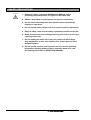
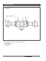
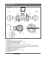
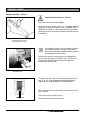
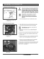
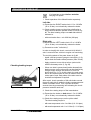
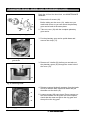
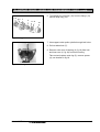
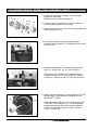
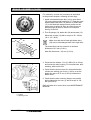
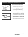
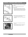
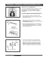
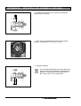
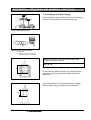
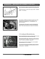
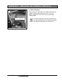
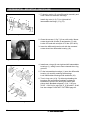
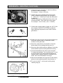
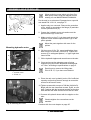
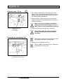
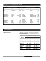
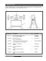
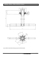
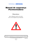
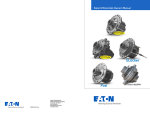
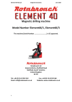
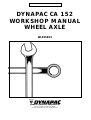
SVEDALA COMPACTION AND PAVING
DYNAPAC CA 152
WORKSHOP MANUAL
WHEEL AXLE
W1055EN1
Svedala Compaction Equipment AB
Box 504, SE-371 23 Karlskrona, Sweden
Phone: +46 455 30 60 00, Fax: +46 455 30 60 30
Vibratory Rollers
CA 152
Work Shop Manual, Wheel Axle
W1055EN1, 98-04-20
Valid for Wheel Axle:
Part No
*37 15 93*
Part No
*37 29 40*
CA W1055EN1
We reserve the right to change specifications without notice.
Printed in Sweden.
1
CONTENTS
Page
Introduction ...................................................................... 3
Safety precautions ........................................................... 4
Lubricants and symbols ................................................... 5
Specifications ........................................................... 5, 6, 7
Brake check ..................................................................... 8
Brake adjustment ............................................................. 9
Disassembly axle from roller .......................................... 10
Preventive check-up....................................................... 11
Planetary gears - Disassembly ................................ 12, 13
Planetary gears - Assembly ..................................... 14, 15
Brakes - Disassembly .................................................... 16
Brakes - Assembly ......................................................... 17
Differential - Pinion housing, Disassembly ..................... 18
Differential - Crown wheel, Removal ........................ 19, 20
Differential - Carrier, Disassembly (P/N 37 15 93) ... 21, 22
Differential - Carrier, Assembly (P/N 37 15 93) .............. 23
Differential - Carrier, Disassembly (P/N 37 29 40) ......... 24
Differential - Carrier, Assembly (P/N 37 29 40) ........ 25, 26
Differential - Measuring and Assembly ..................... 27-31
Differential - Mounting .............................................. 32, 33
Assembly axle to roller ................................................... 34
Starting up ...................................................................... 35
Conversion table ............................................................ 36
Torque table ................................................................... 36
Special tools .............................................................. 37-42
Contact Pattern .............................................................. 43
Trouble shooting ...................................................... 44, 45
Exploded views ......................................................... 46-55
WARNING SYMBOLS
WARNING
Safety instructions – Personal safety
Special caution – Machine or component damage
2
CA W1055EN1
INTRODUCTION
Axle type plate
371593
PART NO.
SERIAL
NO.
The axle type plate is located on top of the differential
housing. The plate shows the manufacturer’s name, part
number (type of axle), PIN “Part Identification Number”
(serial number), year and month of manufacture.
Please state the PIN-number (serial number) of the
axle when ordering spares.
I
726286
98 02
All disassembled mechanical units should be thoroughly
cleaned using appropriate cleaning agent. Parts that
show signs of damage, seizure, cracks or extreme
wear should be remedied or replaced.
In particular, carefully check the status of all moving
parts (such as bearings, gears, shafts) and seals
(o-rings, oil shields) which are subject to major stress
and wear. It is recommended to replace seals every
time a unit is overhauled or repaired. During assembly,
seal rings must be lubricated on the sealing surface. In
case of bevel gear wheel or pinion shaft failure,
replacement of both as a kit is necessary.
Fig. 1 Axle type plate location
During assembly, the prescribed preloading and
backlash of the parts must be obtained.
The use of precision instruments such as, dial gauge,
vernier caliper, micrometer, caliper, slip gauges and
surface plate, is recommended.
For press fits, it is adviceable to use a high sensitive
mechanical press rather than a hydraulic one.
Comply with the torque wrench settings of
bolts and nuts on page 36. Make sure your
torque wrench is in good order.
The exploded views (16422 - 16425, 16497) are the
same as in the SPARE PARTS CATALOG, with the
same position numbers. All position numbers in the
smaller pictures refers to the appropriate exploded
view stated in the page heading. The exploded views
are in the end of the this book.
Exploded views
1
2
3
This wheel axle is mounted as standard on Dynapac
CA 152. In this workshop manual the axle is divided in
three different parts.
2
1
Part 1 is the planetary gears (view 16425, page 52),
part 2 is the brakes (view 16424, page 50) and part 3 is
the differential (view 16423, page 46 and 16497, page
48).
The differential is of a ”limited slip” model, axle
P/N 37 15 93 and can optional be equiped with a ”no
spin” model, axle P/N 37 29 40.
Fig. 2 Different axle parts
1. Planetary gears
2. Brakes
3. Differential
CA W1055EN1
3
SAFETY PRECAUTIONS
WARNING
1. Read and clearly understand WORKSHOP MANUAL before
performing any maintenance or repairs on the wheel axle.
2. Observe and follow all maintenance and service instructions.
3. Do not remove/assembly axle from machine unless qualified by
training or experience.
4. Do not operate roller if wheel axle is in need of repair or adjustment.
5. Obey all safety rules and use safety equipment provided for the job.
6. Block drums and/or tires and apply steering lock before servicing or
repairing wheel axle.
7. Do not modify the wheel axle in any way which will affect safety.
Any modification on this axle requires prior written approval from
Svedala Dynapac.
8. Do not operate machine until hydraulic oil has reached operating
temperature. Braking distance can be extended when oil is cold.
See starting instruction in OPERATING MANUAL.
4
CA W1055EN1
LUBRICANTS AND SYMBOLS
Always use high-quality lubricants, in the quantities
specified. Excess grease or oil can promote
overheating, resulting in premature wear.
HYDRAULIC FLUID
ambient air temperature
-10°C – +40°C (14°F – 104°F)
ambient air temperature
above +40°C (above +104°F)
TRANSMISSION OIL,
ambient air temperature
-15°C – +40°C (5°F – 104°F)
ambient air temperature
above +40°C (above +104°F)
Shell Tellus Oil TX68 or corresponding
Shell Tellus Oil T100 or corresponding
Shell Spirax SAE 80W/90, HD API, GL-5
Shell Spirax HD85W/140 or corresponding
When driving in extremely high or low ambient
temperatures, other lubricants are needed. Contact
Svedala Dynapac.
Hydraulic fluid tank, level
Transmission, oil level
Oil for lubrication
SPECIFICATIONS
Weights and dimensions
Weight, kg (lbs)
Length, without planet carrier, mm (in)
Lenght, with planet carrier, mm (in)
Width, with differential cover, mm (in)
Height, mm (in)
Fluid volumes
37 29 40
300 (661.4)
1270 (50.0)
1530 (60.2)
520,5 (20.5)
270 (10.6)
300 (661.4)
1270 (50.0)
1530 (60.2)
520,5 (20.5)
270 (10.6)
Litre (gal or qts)
Axle 37 15 93:
• Differential ....................................................6 l
• Planetary gears ............................................0,75 l
Axle 37 29 40:
• Differential ....................................................6 l
• Planetary gears ............................................0,75 l
CA W1055EN1
37 15 93
(6.3 qts)
(0.8 qts) / each side
(6.3 qts)
(0.8 qts) / each side
5
SPECIFICATIONS
Rear view
470 Nm (47 kpm), oiled
4
1
2
1
4
3
Fig. 3 Wheel axle, rear view
1.
2.
3.
4.
6
Oil recovery for failsafe brake, breathers mounted (4x)
Oil level plugs
Magnet plugs, oil drain
Oil filling plugs
CA W1055EN1
SPECIFICATIONS
Top view
1
Left side
Right side
4
5
9
10
7
3
8
2
2
8
7
3
6
5
4
Left view
oil level
11
7
8
13
12
Fig. 4 Wheel axle, top and left view
1.
2.
3.
4.
5.
6.
7.
8.
9.
10.
11.
12.
13.
Hydraulic motor
Planetary reduction gear end, right and left
Oil recovery for failsafe brake, breathers mounted (4x)
Bleeding screw for failsafe brake (2x)
Connector for hydraulic fluid to brake,
working pressure min. 14 bar (203 lbs/in2) - max. 30 bar (435 lbs/in2)
Breather
Disc play adjustment screw (2x), four turns á 0,188 mm (0.0074 in) = 0,75 mm (0.03 in)
Manual brake release screw (6x). To release the failsafe brake mechanically, set the screws
by hand until stop. Then torque each screw one turn.
Threaded hole for speedometer sensor
Threaded hole for CCS sensor
Planetary gear end, oil quantity 0,75 litres (0.8 qts)
Oil charge and level plug
Oil drain plug
CA W1055EN1
7
BRAKE CHECK
Brake function – Check
1
WARNING
Check brake function as follows:
2
Drive the machine forward slowly.
Press the reserve brake control (1). The brake warning
lamp on the instrument panel, refer to OPERATION
MANUAL for various levers, lamps and their functions,
should now come on and the machine should come to
a standstill.
Fig. 5 Control panel
1. Reserve brake control
2. Forward/reverse lever
If the brakes have an uneven braking effect or
the braking distance is longer than normal,
check the brake disc thickness and/or perform
an adjustment of the brakes.
1
Perform this check by removing the oil charge/level
plug in the brake part of the axle, see 3, and insert a
measuring instrument and measure the distance
between the brake discs.
Fig. 6 Checking brake disc thickness
1. Oil charge hole
The discs can be used to a minimum thickness of 4,5
mm (0.18 in). If the discs are thinner they must be
replaced, see chapter BRAKE, DISASSEMBLY.
After the brake check, place the forward/reverse lever
(2) in neutral.
Pull up the reserve brake control.
min. 4,5 mm
The machine is now ready to drive.
Fig. 7 Minimum brake disc thickness
8
CA W1055EN1
BRAKE ADJUSTMENT
Adjustment of the brakes
Smaller adjustments may be performed from outside
on this axle (P/N 37 15 93 and 37 29 40).
Refers to brake torque specification.
2
1
For major adjustments and brake disc replacement,
see chapter BRAKE, DISASSEMBLY, page 16.
1. Undo screw (1) and remove locking tab (2)
3
2. Pressurize the brake, min 1.5 MPa (15 bar) and
max 3.0 MPa (30 bar). If the axle is still mounted in
a machine, start the engine. Otherwise use an
external pump, see fig 9.
3. Turn adjusting screw (3) with a spanner counterclockwise until a firm stop is obtained.
4. Thereafter, turn adjusting screw (3) clockwise four
complete turns. Each turn allow 0,188 mm (0,0074
in) play and four turns 0,75 mm (0,03 in) which is
the specified brake disc play.
5 Fit back the locking tab (2) and screw (1).
Fig. 8
Brake adjustment
1. Screw
2. Locking tab
3. Adjusting screw
Fig. 9
Pressurizing the brakes
CA W1055EN1
This adjustment may be performed on both sides of
the axle.
9
DISASSEMBLY AXLE FROM ROLLER
Locking the articulated joint
WARNING
To prevent turning, the steering mechanism
must be locked before hoisting/jacking up
the roller. Move out the arm (1) and secure
it with the cotter (2) to the rear frame of the
machine. Connect the lifting chains, ensuring
that no parts will be crushed when hoisting.
Lifting tackle, such as chains, steel wires,
hydraulic jack, jackstands etc, must be
dimensioned in conformance with current
regulations. When lifting see OPERATION
MANUAL.
1
2
Fig. 10 Right side of articulation
1. Articulation in interlocked mode
2. Locking cotter
1. Lock articulated joint, fig 10, and block the roller.
Removing hydraulic motor
2. Jack up/lift the roller as much that the wheel goes
clear from the ground and remove the wheels.
2
The wheels are very heavy, especially the
liquid ballasted ones.
1
3. Drain the oil from the axle, see MAINTENANCE
MANUAL.
4. Remove the cover plate underneath the hydraulic motor.
Fig. 11 Hydraulic motor mounted on axle
1. Hydraulic motor
2. Screws, 4x
5. Remove, and plug, all the hydraulic (brake) hoses
from the axle.
6. Remove the screws (2, fig 11) holding the hydraulic
motor (1, fig 11) and separate it from the axle.
7. Remove the screws holding the axle in the tractor
frame and remove the axle from the roller.
Put the axle in an axle stand for best and easiest repair
or maintenance. Dynapac have a special axle stand
P/N 12 21 91, see page 37.
Fig. 12 Remove the screws from the
tractor frame
10
CA W1055EN1
PREVENTIVE CHECK-UP
It is important to check before and after
carrying out repairs.
1. Check operation of the failsafe brake separately:
Left side
a) Pressurize the RIGHT brake circuit 1.5 to 3.0 MPa
(15 to 30 bar) or mechanically release the brake.
b) Check rotating torque on the pinion shaft using a
torque wrench and the splined socket 12 29 66, fig
86. The ideal rotating torque on each side without
lubricant is:
- with new brake discs: min. 800 Nm (80 kpm)
Right side
a) Pressurize the LEFT brake circuit 1.5 to 3.0 MPa
(15 to 30 bar) or mechanically release the brake.
b) Proceed as under ”Left side b)”.
In order to simplify this check, use tool kit 90 08 46 if
axle is removed from vehicle or engine not functioning.
The tool kit consists of the parts shown in fig 88.
- Install a 60 bar pressure gauge to test nipple (3, fig.
88) to check the brake release pressure (max 30 bar).
Checking braking torque
- Apply pressure to one side at a time (select side
with the threeway valve (2, fig. 88).
- When one side is pressurized (brake released) the
braking torque on the other side can be checked by
using a torque wrench and socket 12 29 66 on
pinion shaft, fig 13. To do this check, the axle motor
has to be removed after oil level is lowered from the
center part of axle. Both sides of the axle must be
checked and adjusted if required.
Fig. 13 Checking braking torque
After repair, check operation of fail safe brake several
times on each side to settle the brake components and
obtain consistant result. Thus, operate the brake
several times by pressurizing and releasing the circuit
pressure between each test.
2. Check the rotating torque of the transmission:
a) Pressurize the brake on both sides 1.5 to 3.0 MPa
(15 to 30 bar) or mechanically release the brake.
b) Check the rotating torque on the pinion shaft.
The ideal rotating torque is:
- with new components: min. 6 to 8 Nm (0.6 - 0.8 kpm)
- with used components: min. 1 to 1.6 Nm (0.1 - 0.16 kpm)
CA W1055EN1
11
PLANETARY GEARS - WHEEL HUB, DISASSEMBLY (16425)
Drain the oil from the wheel hub, see MAINTENANCE
MANUAL.
17
19
1. Remove the 2 screws (24).
Before taking out the cover (19), make sure you
mark both covers so you can mount the planetary
gear carrier back at the same place.
25
24
22
2. Take out cover (19) with the complete planetary
gear carrier.
Fig. 14 Wheel hub, planetary gear
3. Put the planetary gear carrier upside down and
remove the circlip (17).
17
Fig. 15 Removing circlip from planetary
gear carrier
3. Remove all 3 shafts (22) before you can take out
the planetary gears (25) through the center hole of
the cover (19).
22
Fig. 16 Removing shafts
4. Release eventual hydraulic pressure from the brake
circuit so that the discs cannot fall down and pull
thereafter out the shaft (15).
13
28
5. Loosen screws (28) some turns. Place a spacer on
the screw heads. Let the puller rest on the spacer,
check that the arms are tight to the ring gear and
then pull out the ring gear.
15
Fig. 17 Ring gear
12
CA W1055EN1
PLANETARY GEARS - WHEEL HUB, DISASSEMBLY (16425), contd.
3 4 5
6
6. To separate the ring gear (16) from the flange (13)
remove snap ring (11).
7
6
11 13
16
Fig. 18 Ring gear
7. Use support under puller spindle through bolt holes.
8. Pull out wheel hub (7).
9. Remove outer race of bearing (6, fig 18) from hub
and inner race (6, fig 18) from axle housing.
Take out and replace seal ring (5), remove spacer
(4), see location in fig 18.
Fig. 19 Removing hub
CA W1055EN1
13
PLANETARY GEARS - WHEEL HUB, ASSEMBLY (16425)
3 4 5
6
1. Check the wheel hub bearings (6) for damage.
Replace if necessary.
Replace o-ring (3) and seal ring (5).
7
6
11 13
16
2. Fit new o-ring (3), spacer (4), seal (5) and inner
race of bearing (30) to axle housing.
3. Install the wheel hub (7) onto axle housing and push
in the bearing race (6).
10
28
Fig. 20 Ring gear
4. Check the rotation torque, allowing the taper
bearing a slight end play. The tangential force must
be 20 - 30 N.
Fig. 21 Checking tangential force
5. Measure the difference to establish the required
shim (10, fig 20) size, e.g. 0,9 mm (0.035 in).
Shim packs are available in the following sizes:
0,10 mm (0.004 in), 0,15 mm (0.006 in), 0,20 mm
(0.008 in), 0,30 mm (0.012 in), 0,50 mm (0.020 in).
Fig. 22 Measuring the difference
6. Install ring gear support (13) into ring gear (16) and
locking ring (11) into position. Install all of it into
wheel hub (7, fig 20).
16
28
Clean the screws (28) from old Loctite with Loctite
7070 ODC Free Cleaner or 1,1,1,trichloroethane
(methyl chloroform). Mount the screws (28) with
Loctite 270 and with a torque of 220 - 230 Nm
(162.3 - 169.6 lbf.ft).
Fig. 23 Installing ring gear support
14
CA W1055EN1
PLANETARY GEARS - WHEEL HUB, ASSEMBLY (16425), contd.
7. Insert all 3 planets (25) into planet carrier (19)
through the center hole.
17 18
19
8. Mount washer (27) and bearings (26) before you
mount the shaft (22) with the o-ring (23).
Take care to center the washer (27).
27 26
25
Use of a hydraulic press will simplify the mounting of
the 3 shafts (22).
22 23
Fig. 24 Planetary gear
9. Chamfer after having mounted the circlip (17) as
indicated in fig 25.
17
Fig. 25 Planetary gear
10. Assemble cover (19) with the complete planetary
carrier onto wheel hub.
19
Single offset mounting position of screws (24) and
tighten them with a torque of 86 - 89 Nm (63.4 65.6 lbf.ft).
24
Fig. 26 Mounting planetary carrier onto
wheel hub
Remove the plug (16) and begin fill oil through the
plug-hole until it starts seeping back out again. Refit
the plug.
Use transmission oil. See the lubrication specification
on page 5.
16
Fig. 27 Planetary gear/filling position
16. Plug
CA W1055EN1
15
BRAKE, DISASSEMBLY (16424)
Drain the oil, see MAINTENANCE MANUAL.
1. Release the brakes by pressurizing the brakes 1.5
to 3.0 MPa (15 to 30 bar), fig 9, by using an external
manual pump.
1, 2
2. Remove the nuts (1) and screws (2).
3. When releasing the hydraulic pressure of the brake,
the brake pistong pushes the axle housing away.
Continue to extract the axle housing horizontally,
fig 28.
Fig. 28 Axle housing
13, 14
13, 14
4. Remove screws (13) and springs (14), fig 29 and 30.
Mark position of brake disc (24) with a centrepunch, fig 30, to housing and remove it.
13, 14
Fig. 29 Bolts and springs
5 Remove brake discs (17) and intermediate brake
discs (18), fig 30 and 31.
14
24
13
18
17
Fig. 30 Brake
18
17
In order to keep the same braking torque do
not change the position of the brake discs and
the intermediate brake discs.
Fig. 31 Brake discs
16
CA W1055EN1
BRAKE, ASSEMBLY (16424)
For assembly, reverse the procedure as described
in the previous chapter, renewing all seal rings.
1. Install intermediate brake disc (18) to gear wheel
(23) and continue with brake disc (17) and then next
intermediate brake disc (18) and so on. Brake disc
(17) to be fitted with stamped mark visible on the
same place so when all discs are fitted, there are
holes through all discs to ensure oil circulation.
See fig 32 and 33.
2. Then fit springs (14), brake disc (24) and screws (13).
Fig. 32 Brake disc
Mount the screws (13) with a torque of 20 - 30 Nm
(14.8 - 22.1 lbf.ft).
14
Make sure that the left and right brake discs
(24) are not interchanged from left to right side!
24
13
18
23
The brake discs can be reused to a minimum
thickness of 4,5 mm (0.18 in).
New disc thickness = 4,9 mm (0.19 in).
17
Fig. 33 Brake
4
3
1
26 mm
3
4
3. Pressurize the brakes 1.5 to 3.0 MPa (15 to 30 bar)
and mount the axle housing. Fit nuts and bolts, after
cleaning, with Loctite 243.
4. Check that the three screws for mechanical brake
release are sticking out 26 mm (1.02 in) to set the
brake disc gap to 0,75 mm (0.03 in) between the
brake discs.
5. Check that the axle mounting flanges are parallel
before tightening the nuts (1) with a torque of 120
Nm (88.5 lbf.ft).
Refill unit with oil to correct level, see MAINTENANCE
MANUAL.
Fig. 34 Manual brake release screw
3. Locknut
4. Adjusting screw
CA W1055EN1
17
DIFFERENTIAL - PINION HOUSING, DISASSEMBLY (16423)
Drain the oil from the differential housing, see
MAINTENANCE MANUAL.
25
31
23
22
30
10
26
25
29
24
Fig. 35 Pinion housing
1. Undo screws (31) and washers (30) and
remove the housing.
2. Remove nut (26).
Use wrench, P/N 12 29 65, and socket, P/N 12
29 66, see fig 85, 86 on page 39 and 40.
3. Undo screws (24) and pull out housing (29).
4. Remove the o-ring (23) and the shims (22).
5. Press out pinion shaft (10) from housing (29).
To simplify removal of pinion shaft, use holder
for pinion housing, P/N 12 29 67 fig 87 on page
41.
5. Remove inner bearings (25) from pinion shaft
(10).
6. Remove outer bearing races (25) from housing
(29).
Fig. 36 Pinion parts
18
CA W1055EN1
DIFFERENTIAL - CROWN WHEEL, REMOVAL (16424/16423)
To remove the crown wheel, make sure you have done
the previous chapter PINION HOUSING, DISASSEMBLY
completely.
6
5
Remove retaining ring (6) and cover (5), fig 37.
Left side of axle
1. Remove left axle housing and then the left brake
housing by removing the 2 screws (32). The brake
housing consists of the conical springs (28) that are
attached to the brake piston (27) with a circlip (29).
1
33
29
28
27
32
Fig. 37 Differential housing
2. Remove circlip (29), conical springs (28) and press
out the pistong (27). Check all o-rings.
34
Also check the ventilator (34) for the brake pistong
o-ring failure.
29
28
27
Fig. 38 Ring nut in intermediate housing
3. Remove screw (1), locking plate (3) and undo the
ring nut (3).
4
4. Remove stud bolts (33) with care, and gentle take
out the intermediate housing (pos 1, fig 37).
33
1, 3
Fig. 39 Ring nut in intermediate housing
CA W1055EN1
19
DIFFERENTIAL - CROWN WHEEL, REMOVAL (16424/16423), contd.
Differential housing
If there is no need to separate the crown wheel from
the differential carrier, just take them out through the
left side of the differential housing.
Both axles, P/N 37 15 93 and P/N 37 29 40, have their
crown wheel removed in the same way.
There is no need to remove the right side of axle to
remove the crown wheel and the differantial carrier.
Fig. 39 Differential housing
The easiest way to remove the crown wheel from the
differential carrier is to loosen all the screws while
inside the differential housing. Take it out and remove
the fitting screws completely.
Replace the fitting screws of the crown wheel
every time that they have to be removed.
Fig. 40 Crown wheel
20
CA W1055EN1
DIFFERENTIAL - DIFFERENTIAL CARRIER, DISASSEMBLY (16423)
AXLE P/N 37 15 93 (LIMITED SLIP)
To remove the differential carrier, make sure you have
done the previous chapters PINION HOUSING,
DISASSEMBLY and CROWN WHEEL, REMOVAL
completely.
4
If you don't suspect any fault on the crown wheel, there
is no need to separate it from the differential carrier
1. Take a spacer that just fits over the hole in the
differential carrier and remove the bearing (4) with a
two arm puller, fig 42.
Fig. 42 Differential carrier
2. Mark both parts of the carrier so you can align it
when assembled. Undo the screws (19) and remove
the differential carrier (18).
3. Take out the limited slip disc kit (37), consisting of
different shaped limited slip discs (9, 11, 12), shim
(8), and the differential side gear (13). Remember
the order they where fit.
5
13
11
18
12
4
9
8
19
7
Fig. 43 Differential carrier
4. To remove the shafts (21, 16) you will need to
remove the three pins (17) that holds the shafts.
16
17
16
17
Begin with removing the long shaft (21) then the
smaller ones (16). You can localize the different
shafts by checking the holes on top of the carrier.
There is a small hole for each pin for every shaft.
21
Fig. 44 Differential
CA W1055EN1
21
DIFFERENTIAL - DIFFERENTIAL CARRIER, DISASSEMBLY (16423), contd.
5. Insert a mandrel and firmly tap down the pin into the
shaft (21), stop when you have tapped down the pin
to 30 mm (1.18 in)
30 mm
21
Fig. 45 Removing the shaft pin
6. Remove all three shafts by tapping a hammer on a
mandrel on the opposite side.
Fig. 46 Removing shaft
15
14
13
15
Remove the other differential side gear (13) with the
limited slip disc kit (37), fig 43.
15
16
14
6. Take out the shaft retainer (20), differential pinion
(14) with friction washer (15).
16
17
7. Remove the pins (17) completely from the all the
shafts (16, 21).
20
15
17
21
Fig. 47 Differential
22
CA W1055EN1
DIFFERENTIAL - DIFFERENTIAL CARRIER, ASSEMBLY (16423)
AXLE P/N 37 15 93 (LIMITED SLIP)
1. Check the disc pack to determine the shim thickness.
The total thickness of the disc pack with eventual
shims must be 16,2 mm ± 0,1 mm (0.64 in ± 0.004 in).
Shim packs are available in the following sizes:
0,10 mm (0.004 in), 0,20 mm (0.008 in), 0,30 mm
(0.012 in).
2. Put the limited slip discs with eventual shim (8) and
the side gear with slip discs in differential carrier (6).
3. Arrange the limited slip discs (9, 11) on differential
side gear (13).
Fig. 48 Measuring disc pack
8
4. Insert the shaft (21), tap it in as much as you can fit
one of the differential pinion (14) with a friction
washer (15) onto the shaft. Tap the shaft a bit
further and fit the shaft retainer (20) and the last
differential pinion with a friction washer.
9
12
5
11
20
5. Tap in the two shorter shafts with their respective
differential pinions and friction washers.
13
14
15
21
18
4
19
7
Fig. 49 Differential carrier
17
6. Lock the shafts (21, 16) by fitting the three pins (17).
Tap the pins down 20 mm (0.79 in).
17
7. Put the last side gear with slip discs in place.
17
16
20
mm
8. Mount the differential carrier (18) with screws (19)
and washers (7), fig 49. Lock the screws with Loctite
270 and a torque of 69 - 72 Nm (50.9 - 53.1 lbf.ft).
21
9. Fit the bearing (4), on the differential carrier (18).
Fig. 50 Inserting the shaft pin
CA W1055EN1
23
DIFFERENTIAL - NOSPIN DIFFERENTIAL, DISASSEMBLY (16497)
AXLE P/N 37 29 40 (NoSPIN)
To remove the NoSPIN differential, make sure you
have done the PINION HOUSING, DISASSEMBLY
chapter completely.
1. Mark the differential case halves so they can be
reassembled in their original position when repair or
inspection is completed.
Fig. 51 Inserting the retaining bolt and
washer assembly
2
1
A
B
3
4
5
Fig. 52 Retaining bolt
1. NoSPIN differential assembly
2. Gear support case
3. Wing nut
4. Retaining bolt
5. Retaining washer
2. Insert the NoSPIN differential retaining bolt and
washer assembly. Thread the nut finger tight against
the washer, fig 51. You will note that the retaining
washers must be small enough to pass through the
case ends (dimension A, fig 52), yet large enough to
restrain the two side gears (dimension B, fig 52) and
the balance of the differential assembly when all parts
are assembled and the springs are compressed.
If a retaining and washer assembly are not available,
hold the differential case firmly as the last bolts
are being removed from the case halves to absorb
spring pressure and prevent possible injury.
WARNING
Failure to use a retaining bolt or some other
restraining means when seperating the differential case halves can cause injury in that
NoSPIN differential have compressed springs.
3. Remove crown wheel and bolts.
4. Undo screws and clean them from old Loctite,
seperate the case halves and remove the NoSPIN
differential assembly.
Fig. 53 NoSPIN
5. Release the retaining bolt and washer assembly
while firmly holding the NoSPIN differential to
absorb spring pressure.
6. Remove side gears, springs, spring retainers, driven
clutch assemblies and spider assembly.
For inspection of components refer to NoSPIN
OWNER’S MANUAL.
Fig. 54 NoSPIN disassembled
24
CA W1055EN1
DIFFERENTIAL - NOSPIN DIFFERENTIAL, ASSEMBLY (16497)
AXLE P/N 37 29 40 (NoSPIN)
1. Lubricate all friction surfaces.
2. Assemble a spring retainer over the side gear
splines with the retaining with the retaining lip
pointed up. It should seat against the side gear
shoulder. Place a spring over the side gear spline
and against the retainer lip with the smaller diameter
of the spring against the retainer, fig 55.
Verify that the spring is functioning freely. Be
sure the spring is not binding, that the coils do
not overlap and that there is good contact
between the coil and the spring retainer.
Fig. 55 Spring and retainer mounted on
side gear
3. Assemble the two clutch assemblies to the spider
assembly.
Be sure the ’slot’ in each holdout ring is properly
aligned over the long tooth of the spider assembly.
4. Position the spider assembly and clutch assembly
on top of spring. Assemble the other side in the
same manner as item 2 to 4.
5. Use a mechanical press (or other safe means) to
compress the springs and fasten the NoSPIN
together with a retaining bolt, washers and a wing
nut, fig 56. Be sure the side gear splines are
completely meshed with the clutch spline.
WARNING
Failure to use a retaining bolt or some other
restraining means when seperating the differential case halves can cause injury in that
NoSPIN differential have compressed springs.
6. Lay the ring gear and flanged half of the differential
case on a bench with the bearing end of the case
hub down and the inner case facing up. Ensure no
thrust washers are inside the case.
Fig. 56 Using a mechanical press to
compress the springs
CA W1055EN1
25
DIFFERENTIAL - NOSPIN DIFFERENTIAL, ASSEMBLY (16497), contd.
7. Install the NoSPIN differential in the flanged differential case half and mount the plain case half over
the side gear. Ensure no thrust washers are
inside the case.
8. Position the case halves firmly together with the
punch marks aligned, install the case bolts and lock
them with Loctite 270 and a torque of 135 - 138 Nm
(99.6 - 101.8 lbf.ft). Ensure a tight fit between the
two case halves.
Fig. 57 NoSPIN differential with crown
wheel mounted
9. Remove the wing nut, washers and retainer bolt,
install the crown wheel and lock the bolts with
Loctite 270 and a torque of 73 Nm (53.8 lbf.ft).
Before operating the vehicle, perform installation and operation test and refer to NoSPIN
OWNER’S MANUAL to ensure correct
assembly.
26
CA W1055EN1
DIFFERENTIAL - MEASURING AND ASSEMBLY (16423/16424)
Assemblage of the pinion can be considered in four
parts:
B
A
1.
2.
3.
4.
I
C
Height of pinion
Pre-loading of pinion bearing
Pre-loading of differential bearing
Gear flank play
1. Height of pinion
Measure the size of the intermediate spacer S2
using the following formula:
S2 = (B + A) - (I + C)
S2
See fig 58.
S1
Fig. 58 Differential housing
B = Diameter of centre housing divided by two plus
material thickness D.
Ø
D
Fig. 59 Differential housing
CA W1055EN1
27
DIFFERENTIAL - MEASURING AND ASSEMBLY (16423/16424)
A
A = Distance from block level of pinion housing and
bottom face of bearing.
Fig. 60 Differential housing
I = This value is punched into the head of the pinion
spindle, for example: 117 mm (-0,1), 4.6 in.
I
Fig. 61 Pinion spindle
C = Width of bearing.
The old intermediate spacer can be used if the
pinion housing is not changed. Just adjust the
spacer to compensate for any difference in
the I value, fig 61, of the new pinion.
C
Fig. 62 Width of bearing
28
CA W1055EN1
DIFFERENTIAL - MEASURING AND ASSEMBLY (16423/16424)
2. Pre-loading of pinion bearing
S2
Fit the measured spacers S2 into the pinion housing as
shown in fig 63 and fit both outer bearing rings.
S1
Fig. 63 Differential housing
33
34
Fig. 64 Pinion spacer and shim
23. Spacer
24. Shim 0,10 mm, 0,15 mm,
0,20 mm, 0,40 mm, 050 mm
Measure the size of the intermediate spacer S1
using the following formula:
S1 = A - B
See fig 65 and 66.
A
Fit the bearings without spacer ring. Place the pinion
housing on a flat-ground surface and measure the
distance A.
Fig. 65 Measuring the A distance
Lift out the bearings. Then assemble these together
with the spacer ring and measure the distance B.
B
Fig. 66 Measuring the B distance
CA W1055EN1
29
DIFFERENTIAL - MEASURING AND ASSEMBLY (16423/16424)
Mount the pinion spindle (10) with bearing (25), spacer
ring (33) and the measured spacers S1 (33) and S2 (22).
34
10
26
Tighten the pinion nut (26) with a torque of 900 - 1000 Nm
(663.8 - 737.6 lbf.ft).
25
33
22
Fig. 67 Pinion housing
Use wrench 12 29 65 and socket 12 29 66, see page
39 and 40. Then measure the pre-loading of the
bearing which should be 1,2 - 1,5 Nm (0.89 - 1.11
lbf.ft), see fig 68.
The thickness of the spacers must be adjusted if the
bearing load is not within the values recommended
above. Then seal the pinion nut (26) with Loctite 243.
Fig. 68 Tightening pinion nut
3. Pre-loading of differential bearing
Mount the differential housing complete with bevel gear
wheel and bearing and both brake housings.
Apply a mild sealant, type Loctite 222, to the ring nuts
and adjust the pre-loading of the bearings with the aid
of tool 12 29 64, see fig 84 on page 38.
Ensure at the same time that there is an acceptable
gear flank play (0.18 - 0.25 mm).
The correct pre-load of the bearings is that measured
under item 2 ”Pre-loading of pinion bearing”, plus 0,3 0,4 Nm (0.22 - 0.30 lbf.ft).
Fig. 69 Adjusting pre-load
30
CA W1055EN1
DIFFERENTIAL - MEASURING AND ASSEMBLY (16423/16424)
4. Gear flank play
When the correct pre-load is set, adjust both ring nuts
equally until the gear flank play is 0,18 - 0,25 mm
(0.007 - 0.010 in). Then secure the ring nuts with
locking plates.
0,18 - 0,25 mm
No further adjustment will be required to give
the right gear pattern if the height of the pinion
and the gear flank play are correctly set.
Fig. 70 Adjusting gear flank play
CA W1055EN1
31
DIFFERENTIAL, MOUNTING (16423/16424)
1. Fit bearing carrier (5) onto differential assembly and
outer races into the brake housings.
1
2 3
4
5
4
6
Install ring nuts (4, fig 71) in right and left
intermediate housings (1, fig 73).
3
7
2 1
Fig. 71 Assembly the differential
2. Clean the screws (6, fig 71) from old Loctite. Mount
crown wheel with screws (6) and washer (7) with
Loctite 270 and with a torque of 73 Nm (53.8 lbf.ft).
3. Insert the differential carrier unit with the mounted
crown wheel into differential housing (10).
Fig. 72 Assembly the differential
4. Install new o-rings (9) onto right and left intermediate
housings (1), taking care to have cleaned the o-ring
grooves.
1
4
1
9
9
29
33
16
5. Fit the intermediate housings (1) onto the differential
housing (4) carefully entering the bearings.
Lock intermediate housings with stud bolts (33).
6. Turn in ring nuts (4, fig 71) without preloading the
bearings until a minimum backlash is obtained
between the teeth of the bevel gear wheel and
pinion shaft: Backlash allowed = 0,18 - 0,25 mm
(0.007 - 0.010 in) for axle P/N 37 15 93 and 37 29 40,
see also chapter CONTACT PATTERN page 43.
28
27
12
Fig. 73 Differential housing
32
CA W1055EN1
DIFFERENTIAL, MOUNTING (16423/16424)
7. Check the torque necessary to rotate the differential with no load on bearings.
For example: 1.6 Nm (1.18 lbf.ft).
8. Tighten ring nut on opposite side of bevel gear
wheel, preloading the bearings until a torque of
3 - 4 Nm (2.21 - 2.95 lbf.ft) to rotate the differential
is obtained.
Seat the bearings by rotating them fully clock- and
counterclockwise. Then check the torque again.
For example: 1.9 to 2.0 Nm (1.40 - 1.48 lbf.ft).
Fig. 74 Checking torque
9. Check tooth contact pattern of gear set, fig 75. See
also chapter CONTACT PATTERN on page 43.
Apply marking compound to some teeth of bevel
gear wheel.
Fig. 75 Correct contact pattern
3
2
10. Rotate the gear set clock- and counterclockwise so
that tooth contact pattern is obtained on both
surfaces of the gear teeth.
1
10
1 2
3
a) Move the crown wheel (10) towards or from the
pinion shaft (10) by turning the ring nuts (3).
b) Move the pinion shaft axially by adding or removing
shims between pinion housing and axle housing.
11. Check the backlash of the bevel gear set again.
To adjust the backlash: Turn ring nuts only, i.e. turn
the nut on bevel gear wheel side and tighten the
opposite side for equal measure if backlash is too
small; visa versa if backlash is too large.
10
Fig. 76 Differential
12. With correct backlash, lock ring nuts (3) with locking
plates (2) onto optimal position using screws (1).
13. Fit cover (9), fig 77, on the axle housing using
retaining ring (8).
9
8
Fig. 77 Differential housing
CA W1055EN1
33
ASSEMBLY AXLE TO ROLLER
When recieving a new wheel axle from Svedala Spare Parts it must be drained from all
existing oil, see MAINTENANCE MANUAL.
Put the axle in an axle stand. Dynapac have a special
axle stand P/N 12 21 91, see page 37.
8
5
6
7
Fig. 78 Connection to the hydraulic motor
1. Applies only to a new axle: Remove the protection
cover, which is mounted on the flange (6) and take
out the splined sleeve (8).
2. Grease the hydraulic motor axle and mount the
splined sleeve (8) on the axle.
3. Make sure the o-ring (7) is in place and mount the
hydraulic motor with the splined sleeve (8) on the
pinion spindle.
Mount the parts together with care for the
splines.
Mounting hydraulic motor
2
1
6. Oil the screws (2, fig 79), mount and tighten them
with a torque of 270 Nm (199.2 lbf.ft). Tighten the
screws (2) in a diagonal pattern, i.e. upper right then
lower left etc.
7. Oil the hydraulic nipples and mount them on the axle.
8. Clean and mount the planetary gear oil plugs,
magnetic plug and fill the differential housing with
oil, 6 liter, according to specifications on page 5.
Fig. 79 Hydraulic motor mounted on axle
1. Hydraulic motor
2. Screws, 4x
Dont forget to remove the lifting plate,
P/N 12 24 37, if you have one installed.
9. Place the axle on a hydraulic jack or lift of sufficient
capacity and jack up the axle enough to mount the
screws in the tractor frame.
10. Tighten screws with a torque of 330 Nm (243.4 lbf.ft).
Begin with the two innermost screws, fig 80, on one
side. Continue with the innermost screws on the other
side and then the other screws on one side at a time.
11. Connect all hydraulic hoses with the nipples on the
axle.
Check/retighten the connections on the
machine.
Fig. 80 Mounting the screws
Continue with the next chapter on page 35.
34
CA W1055EN1
STARTING UP
Hydraulic tank - Fill up
1
1. Fill up with fresh hydraulic fluid through the filler
pipe (2) as per the lubricant specification on page 5.
Replace the hydraulic fluid filters at the same time,
see MAINTENANCE MANUAL.
2. Start the diesel engine and let it run on idle for a
couple of minutes. Check and operate the various
hydraulic functions.
WARNING
2
Fig. 81 Hydraulic fluid tank
1. Filler pipe
2. Sight glass
Make sure there is adequate ventilation
(extraction) if the diesel engine is run indoors. (Risk of carbon monoxide poisoning).
3. Check the fluid level and top up if necessary.
WARNING
Never work under the roller with engine
running. Block the drum and wheels if
necessary.
Releasing the articulated joint
Remember to restore the articulation interlock
to its open mode before driving again.
4. Release the articulated joint, fig 82.
After the first 50 operating hours, change the
transmission oil in the axle.
1
Fig. 82 Right side of articulation
1. Articulation in open mode
CA W1055EN1
35
METRIC/U.S. CONVERSION TABLE
To convert
from
into
To convert
from
into
Bar
Celsius (°C)
Centimeters
Cubic centimeters
Cubic inches
Cubic meters
Fahrenheit (°F)
Gallons (US)
Gallons/min
Inches
Inches
Kilograms
Kilograms/cm
Kilometers
Kilometers/hr
Liters
Pounds/sq in
14,504
Fahrenheit
(°C x 9/5) + 32
Inches
0,3937
cu inches
0,06102
cu centimeters
16,3872
cu feet
35,31
Celsius
(°F - 32) x 5/9
Liters
3,785
Liters/sec
0,063
Centimeters
2,54
Millimeters
25,4
Pounds
2,205
lbs/in
5,60
Miles
0,6214
Miles/hr
0,6214
Gal (US)
0,264
Liters
Meters
Milimeters
Newton meters (Nm)
Newton meters (Nm)
Pounds
Pound-feet
Pound-inches
Pounds/in
quarts (liq)
Sq cm
Sq inches
Sq meters
Sq milimeters
Temp (°F) - 32
Tons (metric)
Qts (US)
Inches
inches
Pound-inches
Pound-feet
Kilograms
Newton meters (Nm)
Newton meters (Nm)
Kilograms/cm
Liters
sq inches
sq cms
sq feet
sq inches
Celcius (°C)
Pounds
Multiply by
Multiply by
1,057
39,37
0,03937
8,8507
0,7376
0,4536
1,3556
0,1130
0,1786
0,9463
0,155
6,452
10,76
0,00155
5/9
2205,0
TORQUE TABLE
Tightening torque
Tightening torque in Nm (lbf.ft) for oiled bolts when
using a torque wrench.
Use SHELL ONDINA 32 oil alt. SHELL RETINAX 15.
M
36
STRENGTH CATEGORY
thread
8.8 (Grade 5)
10.9 (Grade 8)
M4 X 0,7
M5 X 0,8
M6 X 1
M8 X 1,25
M10 X 1,5
M12 X 1,75
M16 X 2
M20 X 2,5
M24 X 3
M30 X 3,5
M36 X 4
2,5 (1.8)
4,9 (3.6)
8,4 (6.2)
21 (15.5)
40 (29.5)
70 (51.6)
169 (124.7)
330 (243.4)
570 (420.4)
1130 (833.5)
1960 (1445.7)
3,4 (2.5)
7,0 (5.2)
12
(8.9)
28 (20.7)
56 (41.3)
98 (72.3)
240
(177)
470 (346.7)
800 (590.1)
1580 (1165.4)
2800 (2065.3)
CA W1055EN1
SPECIAL TOOLS
In order to simplify a repair it is recommended to have some special tools. We will therefore upon
request supply drawings so you can make them yourself.
2
1
Fig. 83 Axle stand with mounted complete axle
Dynapac P/N
Description
Qty
Remarks
12 21 91
Axle stand for complete axle.
Pos. 1 in fig 83 above.
1
Drawings
Necessary
50 00 93
Screw M 16 x 40.
Pos. 2 in fig 83 above.
2
Necessary
12 29 64
Wrench and socket for bearing ring
nut in differential housing, fig 84.
1
Recommended
12 29 65
Wrench for pinion nut,
fig 85.
1
Necessary
12 29 66
Socket for pinion nut,
fig 86.
1
Necessary
12 29 67
Holder for pinion housing,
fig 87.
1
Helpful
90 08 46
Tool kit for brake adjustment,
fig 88.
1
Helpful
CA W1055EN1
37
SPECIAL TOOLS - TOOL KIT P/N 12 29 64
27
12
17
310
425
55
9 6
ø85
ø50
ø47
ø38 -- 0,1
0,2
500
+ 0 ,5
-0
56
±
10
ø80
1
0,
±
69
1
0,
45°
45°
Fig. 84 Wrench and socket for bearing ring nut, tool kit P/N 12 29 64
38
CA W1055EN1
SPECIAL TOOLS - TOOL KIT P/N 12 29 65
75
53
5
17
60
ø6
ø70
-0
ø85
6
ø50 + 0,05
6
5
400
15°
5 x 45°
5 x 45°
10
40
Fig. 85 Wrench for pinion ring nut, tool kit P/N 12 29 65
CA W1055EN1
39
SPECIAL TOOLS - TOOL KIT P/N 12 29 66
90
1 x 45°
ø60
+ 0,1
19,2 + 0,2
+ 0,1
+ 0,1
ø7 + 0,2
ø28 + 0,2
50
1 x 45°
1 x 45°
- 0,1
+ 0,1
ø34 + 0,2
20
ø50 - 0,2
20
Fig. 86 Socket for bearing ring nut, tool kit P/N 12 29 66
40
CA W1055EN1
ø110
110
38
+0
40
ø25
40
ø32 - 0
134 ± 0,2
115
253
215
13
+ 0,15
+ 0,3
100
SPECIAL TOOLS - TOOL KIT P/N 12 29 67
145 ± 0,1
175 ± 0,1
220
150
25
50
45
45°
160 ± 0,2
14
30
80 ± 0,2
115
225
Fig. 87 Holder for pinion housing, tool kit P/N 12 29 67
CA W1055EN1
41
SPECIAL TOOLS - TOOL KIT P/N 90 08 46
This tool kit is helpful to make brake adjustment work
easier. (Only parts in fig 88 are included in the kit,
except from the adapters P/N 90 05 52).
1
It can be used on all rear axles with P/N: 37 15 93 and
37 29 40.
3
2
3
Fig. 88 Tool kit P/N 90 08 46 for brake
adjustment
1. Adapters for use with a new axle
P/N 90 05 52
2. 3-way valve
3. Test nipple
Connect a 60-bar pressure gauge to test nipple (3) to
keep control on not exceeding the maximum brake
release pressure (30 bar).
With this device, one side at a time can be pressurized
(brake released) in order to allow brake torque check
on the other side by using a torque wrench and the
socket for the pinion P/N 12 29 66 (fig. 86) or make a
splined sleeve with a 3/4 square drive to match the
wrench.
Smaller adjustments may be performed by using the
external square headed adjusting screw under the
locking tab above the manual brake release screw (see
fig 8) on each side. Total min brake disc play 0,75 mm
(0.03 in) must be obtained.
The hydraulic motor has to be removed to perform this
check. Select side with the 3-way valve (3).
Minimum allowed torque per each side:
Axle type, P/N
New and reconditioned axles
37 15 93
37 29 40
800 Nm (80 kpm)
800 Nm (80 kpm)
Fig. 89 Checking the torque
42
CA W1055EN1
CONTACT PATTERN
Correct contact pattern
Incorrect contact pattern
Move thus to obtain correct
contact pattern
1.
2.
3.
4.
5.
6.
7.
Do not use bevel gear sets with
such incorrect contact patterns
8.
Do not use bevel gear sets with
such incorrect contact patterns
CA W1055EN1
43
TROUBLE SHOOTING
Trouble
Insufficient braking
Overheating
Possible cause
Correction
1. Incorrect adjustment
Inspect disc thickness, see
page 8, and if discs are usable
readjust brakes to the
specifications on page 9.
2. Brake discs worn out
Inspect disc thickness, see
page 8, and replace if
necessary, see page 16-17.
3. Oil level wrong
Drain, flush and refill to proper
level.
4. Too small of a brake gap
Readjust brakes to the
specifications in the vehicle's
service manual
5. Park brake dragging
Unlock the brake and adjust the
correct gap.
6. Air in brake circuit
Open the bleeders for a second,
see pos 10-11 on page 52.
7. Restriction in return line of Inspect for and replace
brake Servo system
damaged return line.
Inspect for and remove any
filter, tee’d in line or any other
source of back pressure from
the return line.
Diff-lock inoperative
8. Incorrect lubricant
Change the retaining rings of
the brake circuit and brake pump.
9. Loose or misadjusted
linkage
Inspect and correct linkage and
readjust as indicated in
vehicle's service manual.
10. Worn discs in limited slip
Replace discs as described on
page 16.
Oil coming out of breather
11. Leak in internal brake
system
Replace the four o-rings on the
brake piston, see page 19.
NoSPIN indexing noise when
driving straight
12. Unequal tire pressure left
and right
Inflate tires to the recommended
pressure in the service manual,
or until the rolling radius is equal.
13. Different style, size or brand Change tires to make the radius
of tires between left and
equal. Vary tire pressure within
right hand side.
the specifications until the rolling
radius is equal.
44
CA W1055EN1
TROUBLE SHOOTING
Trouble
Noise during coast and under
power the same
Possible cause
14. Wheel bearings damaged
Noise under power greater than 15. Low oil level
during coast
16. Incorrect lubricant
Correction
Replace and adjust as described
on page 12 - 15.
Refill oil to proper level.
See correction no. 8.
17. Ring and pinion worn
Inspect through rear cover.
Replace and adjust as described
on page 18 and from 27 to 31.
18. Worn ring and pinion
bearings
Replace and adjust as described
on page 18 and from 27 to 31.
19. Worn planetary gears or
bearings
Replace as described from
page 12 to 15.
20. Loose pinion nut
Inspect ring, pinion and pinion
bearings. If undamaged,
retighten nut as described from
page 32 to 33.
21. Only one pinion bearing
damaged
See correction no. 18.
Noise during turn
(without NoSPIN)
22. Worn spider and/or side
gears
Replace as described from
page 21 to 23 or 24 to 26
dependent on axle type.
A ”Stick slip” noise when going
from forward to reverse
23. Loose wheel
Inspect for wheel and wheel
stud damage. Replace if
needed and retorque lugnuts.
24. Shaft pins loose in
differential carrier
Inspect through rear cover.
Replace as described from
page 21 to 23 or 24 to 26
dependent on axle type.
Noise during coast greater than
under power
25. Damaged or missing spider See correction no. 22.
and/or side gear washers
CA W1055EN1
45
EXPLODED VIEW 16422 - REAR AXLE
Fig. 90 Rear axle, Spare Parts picture no 16422
46
CA W1055EN1
EXPLODED VIEW 16422 - REAR AXLE
Pos Qty Part No
1
2
3
4
5
6
7
8
9
1
1
1
1
2
2
1
1
8
1
1
37 15 93
37 29 40
93 60 58
93 60 59
90 95 84
93 60 60
92 68 10
CA W1055EN1
Description
Rear axle
Rear axle
.Differential (Axle P/N 37 15 93)
.Differential (Axle P/N 37 29 40)
.Brakes
.Planetary gear
.O-ring
.Flange
.O-ring
.Splined sleeve
.Plug
Notes
See fig. 91
See fig .92
See fig. 93
See fig. 94
47
EXPLODED VIEW 16423 - DIFFERENTIAL WITH LIMITED SLIP
Fig. 91 Differential with limited slip, Spare Parts picture no 16423
Loctite 222
Loctite 243
Loctite 270
48
CA W1055EN1
EXPLODED VIEW 16423 - DIFFERENTIAL WITH LIMITED SLIP
Pos Qty Part No
1
2
3
4
5
6
7
8
9
10
11
12
13
14
15
16
17
18
19
20
21
22
23
24
25
26
29
30
31
33
34
35
36
37
1)
2)
2
2
2
2
1
16
24
2
2
2
8
1
10
2
2
4
4
2
3
1
8
1
1
1
1
1
1
1
12
2
1
1
8
8
1
1
1
1
1
1
2
2
2
90 95 47
93 60 21
93 60 22
93 60 23
93 60 24
93 60 25
93 60 26
93 60 27
93 60 28
93 60 29
93 60 31
93 60 34
93 60 35
93 60 36
93 60 37
93 60 38
93 60 39
93 60 40
93 60 41
93 60 42
93 60 43
93 60 44
93 60 45
93 60 46
93 60 47
93 60 48
92 61 16
93 60 49
93 60 50
93 60 51
90 95 82
93 60 52
93 60 53
93 60 54
93 60 55
93 60 56
93 60 57
90 95 44
90 95 37
93 61 08
Description
Screw
Locking plate
Ring nut
Bearing
Differental carrier
Screw
Washer
Shim
Shim
Shim
Lim. slip disc
Bevel gear set
Lim. slip disc
Lim. slip disc
Diff. side gear
Diff. pinion
Friction washer
Pin
Pin
Cover
Screw
Shaft retainer
Pin
Shim
Shim
Shim
Shim
O-ring
Screw
Bearing
Ring nut
Cover
Washer
Screw
Shim
Shim
Shim
Shim
Shim
Spacer
Screw
Washer
Lim. slip disc kit
Notes
0.10 mm
0.20 mm
0.30 mm
Use item 37
1)
Use item 37
Use item 37
0.15
0.20
0.50
0.10
mm
mm
mm
mm
0.10
0.15
0.20
0.40
0.50
mm
mm
mm
mm
mm
2)
Consists of crown wheel and pinion shaft
1 kit include item 9, 11 and 12 for one side. 2 kits are needed for one axle.
CA W1055EN1
49
EXPLODED VIEW 16497 - DIFFERENTIAL WITH NoSPIN
3
4
5
1
6
4
1
7
2
2
22
25
21
5
15
11
8
24
3
7
12
14
17
10
18
9
13
23
16
9
20
19
Fig. 92 Differential with NoSPIN, Spare Parts picture no 16497
Loctite 222
Loctite 243
Loctite 270
50
CA W1055EN1
EXPLODED VIEW 16497 - DIFFERENTIAL WITH NoSPIN
Pos Qty Part No
1
2
3
4
5
6
7
8
9
10
11
12
13
14
15
16
17
18
19
20
21
22
23
24
25
2
2
2
1
1
1
2
16
2
2
1
1
1
1
1
1
Description
Hexagon bolt
Sheet
Taper roller bearing
Differential carrier
Bevel gear set
No-spin differential
Ring nut
Cylinder bolt
Bearing
Bearing
Spacer
Shim
Shim
Shim
Shim
Shim
1
1
1
1
8
8
1
Shim
Shim
Shim
Shim
Spring washer
Hexagon bolt
Ring nut
12
1
16
16
1
2
2
Hexagon bolt
Cover
Spring washer
Hexagon bolt
O-ring
Washer
Bolt
CA W1055EN1
Notes
51
EXPLODED VIEW 16424 - DIFFERENTIAL HOUSE AND BRAKES
Fig. 93 Differental house and brakes, Spare Parts picture no 16424
Loctite 270
52
CA W1055EN1
EXPLODED VIEW 16424 - DIFFERENTIAL HOUSE AND BRAKES
Pos Qty Part No
1
2
3
4
5
6
7
8
9
10
11
12
13
14
15
16
17
18
19
20
21
22
23
24
25
26
27
28
29
30
31
32
33
34
35
1)
2
1
2
1
1
1
3
1
2
2
2
2
6
6
6
6
10
10
2
2
2
2
2
2
4
4
2
4
2
2
4
4
6
4
2
93 60 18
90 09 26
92 67 32
93 60 19
90 95 42
92 96 17
92 68 10
90 95 40
93 60 20
93 60 87
93 60 88
93 60 89
93 60 90
93 60 91
93 60 92
93 60 93
92 96 91
90 09 37
93 60 96
93 60 97
93 60 98
93 60 99
93 61 00
93 61 01
93 61 02
93 61 03
93 61 04
93 61 05
93 61 06
90 96 25
93 61 07
90 96 15
93 61 09
Description
Intermediate housing
Ventilator
Plug
Housing
Plug
Snap ring
Magnet plug
Plug
O-ring
Plug
Bolt
Intermediate cover
Screw
Spring
Washer
Nut
Brake disc
Brake disc
O-ring
Screw
Locking plate
Pinion
Ring
Brake disc
O-ring
O-ring
Piston
Spring
Circlip
Pin
O-ring
Screw
Adjusting bolt
Ventilator
Brake disc kit
Notes
Use item 35
Use item 36
1)
1 kit include item 17 and 18 for one side. 2 kits are needed for one axle.
CA W1055EN1
53
EXPLODED VIEW 16425 - PLANETARY GEAR
Fig. 94 Planetary gear, Spare Parts picture no 16425
Loctite 270
54
CA W1055EN1
EXPLODED VIEW 16425 - PLANETARY GEAR
Pos Qty Part No
1
2
3
4
5
6
7
8
9
10
11
12
13
14
15
16
17
18
19
20
21
22
23
24
25
26
27
28
29
30
31
32
33
2
16
2
2
2
4
2
16
2
2
2
2
2
2
2
2
2
16
2
2
2
2
2
2
2
6
6
4
6
12
6
16
24
2
2
4
4
93 60 61
92 67 81
93 60 62
93 60 63
92 61 85
93 60 64
93 60 65
90 19 87
93 60 66
93 60 67
93 60 68
93 60 69
93 60 70
93 60 71
93 60 72
93 60 73
93 60 74
90 96 05
93 60 75
93 60 76
93 60 77
90 95 98
93 60 78
90 96 07
90 95 96
93 60 79
93 60 80
92 96 61
93 60 81
93 60 82
93 60 83
90 95 89
93 60 84
92 68 10
92 67 32
93 60 85
93 60 86
CA W1055EN1
Description
Housing
Stud
O-ring
Spacer
Seal
Bearing
Hub
Nut
O-ring
Shim
Shim
Shim
Shim
Shim
Snap ring
Seal
Flange
Bushing
Shaft
Ring gear
Circlip
Friction washer
Planet carrier
Seal
Plug
Pin
O-ring
Screw
Planet gear
Bearing
Washer
Bolt
Bolt
Plug
Plug
Stud
Nut
Notes
0.15
0.20
0.50
0.30
0.10
mm
mm
mm
mm
mm
55