1
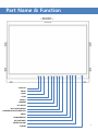
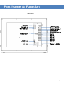
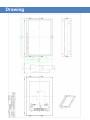
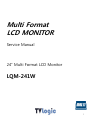
Multi Format
LCD MONITOR
Service Manual
24” Multi Format LCD Monitor
LQM-241W
1
Caution
• Always use set voltage.
- AC 100 ~ 240V
- DC 24V [Tpy. 3.2A]
All operating instructions must be read and understood before the products is operated.
• These safety and operating instruction must be kept in safe place for future reference.
• All warning in this instruction must be observed closely and be followed.
• Do not use attachments not recommended by the manufacturer. Use of inadequate attachments
can result in accidents.
• If you are not sure of the type of power supply used in your home, consult your dealer or local
power company. For units designed to operate on batteries or another power source, refer to the
operating instruction.
• The power cord must be routed properly to prevent people from stepping on them or objects
from resting on them. Check the cords at the plugs and products.
• Do not overload DC outlets or extension cords. Overloading can cause fire or electric shock.
• Do not attempt to service the products yourself. Removing covers can expose you to high voltage
and other dangerous conditions. Request a qualified person to perform servicing.
• If any of the following conditions occurs, unplug the power cord from the DC outlet, and request a
qualified service person to perform repairs.
a. When the power cord or plug in damaged.
b. When a liquid was spilled on the products or when objects have fallen into the products.
c. When the products have been exposed to rain or water.
d. When the products have been dropped or damaged.
e. When the products display an abnormal condition. Any noticeable abnormality in the products
indicate that the products need servicing.
• Upon completion of service of repair work, request the service technician to perform safety checks
to ensure that the products is in proper operating condition.
• Keep the products away from direct rays of the Sun-light.
• Do not place the products on an unstable cart, stand, tripod or table. Placing the products on an
unstable base can cause the products to fall.
• When you disassemble the products, you lay smooth fabric so that the products keep away from
scratch.
• When you assemble the products, you set the electronic screwdriver’s torque as less than 2k and
screw each bolt and check if the cables connect properly. Setting the torque as more than 2k can
cause the case broken.
2
Part Name & Function
<FRONT>
ANALOG
MODE
QUAD
SCAN
ASPECT
MARKER
H/V DELAY
BLUE ONLY/MONO
CHROMA/PHASE/SCREEN SEL
MENU
DOWN/BRIGHT
UP/CONTRAST
ENTER/VOLUME
POWER
3
Part Name & Function
<REAR>
REMOTE
RS-422 IN
RS-422 OUT
HDMI(HDCP)
AUDIO IN
AUDIO OUT
DC 24V
Factory PGM1
Factory PGM2
CVBS1/G/Y/S-Y
CVBS2/B/Pb
CVBS3/R/Pr/S-C
DVI-I
SDI-A
SDI-B
SDI-C
SDI-D
Power & AC IN
4
Drawing
Disassemble Drawing
Other
Functions
DVI
ANALOG/DIGITAL
Supportive Resolution
DVI ANALOG/DIGITAL Supportive Resolution
• DVI-ANALOG :
Resolution
Frequency
640 × 480
60Hz, 75Hz
720 x 400
70Hz
800 × 600
60Hz, 72Hz, 75Hz
1024 × 768
60Hz, 70Hz, 75Hz
1366 x 768
60Hz/75Hz
1280 x 1024
60Hz/75Hz
1600 x 1200
60Hz
1920 x 1080
60 Hz
• DVI DIGITAL Graphic Mode :
Resolution
Frequency
640 × 480
60Hz, 75Hz
800 × 600
60Hz, 72Hz, 75Hz
1024 × 768
60Hz, 70Hz, 75Hz
1366 x 768
60Hz/75Hz
1280 x 1024
60Hz/75Hz
1600 x 1200
60Hz
1920 X 1080
60hZ
1920 x 1200
60 Hz
• DVI DIGITAL Video Mode :
SMPTE-274M
1080i (60 / 59.94)
SMPTE-296M
720p (60 / 59.94)
SMPTE-125M
480i (59.94), 480p(59.94)
• DVI DIGITAL has two type : Graphic and Video.
• As in DVI ANALOG/DIGITAL mode, if it is not setting ZERO Scan on Scan mode, the screen might
be shown as an abnormal image.
• .If the setting on Aspect mode not Wide Screen, you can push ASPECT button then it shows Wide
Screen.
7
Specification
LQM-241W
Input
Output
Input Signal
Analog Input Spec
1 x DVI-I
DVI-I(RGB) IN
3 x BNC
Analog Input
4 x BNC
SDI A/B/C/D Channel Input
1 x HDMI
HDMI Input
3 x BNC
Analog Output
4 x BNC
SDI A/B/C/D Channel (Active Through Out)
Analog
Composite / S-Video / Component / RGB
HD-SDI
1.485Gbps
SD-SDI
270Mbps
DVI
VESA/IBM Modes
HDMI
480i/480p/720p/1080i & VESA/IBM Modes
Composite
1.0Vpp (With Sync)
S-Video
1.0Vpp (Y With Sync), 0.286Vpp(C)
Component
1.0Vpp (Y With Sync), 0.7Vpp (Pb,Pr)
RGB
1.0Vpp (G With Sync), 0.7Vpp (B,R)
SMPTE-274M
SDI Input Signal
Formats
1080i (60/59.94/50)
1080p (30/29.97/25/24/24sF/23.98/23.98sF)
SMPTE-296M
720p (60/59.94/50)
SMPTE-260M
1035i (60/59.94)
SMPTE-125M
480i (59.94)
ITU-R BT.656
576i (50)
2K Format
2048 x 1080(23.98p/psf, 24p/psf)
Audio In
Embedded Audio / Analog Stereo (Phone Jack)
Audio Out
Analog Stereo (Phone Jack). Internal Speaker(Stereo)
LCD
Size
24”
Resolution
1920 x 1200 (16:10)
Pixel Pitch
0.270(H) x 0.270(W) mm
Color
16.7M(true 8bit)
Viewing Angle
H : 176 degrees / V : 176 degrees
Luminance of
white
500 cd/㎡(Center)
Contrast
1000:1
Display Area
518.4(H) x 324.0(V) mm
Power
24V DC / AC100~240V
Power Consumption (Approx.)
77 Watts(Max)
Operating Temperature
0°C to 40°C (32°F to 104°F)
Storage Temperature
-20°C to 60°C (- 4°F to 140°F)
Main Body Dimensions (mm/inch)
552.5 x 389 x 95 (21.73 x 15.31 x 3.74)
Main Body Dimensions (With Stand)
586 x 417 x 150 (23.07 x 16.41 x 5.90)
Weight
11Kg / 24.2 lb
Accessory
AC Power cord, Manual
Option
Carrying case, 19” Rack Mountable Kit, ND Filter
* 위 사양은 예고 없이 변경될 수 있습니다.
8
PCB Block Diagram
9
Circuit Operation Progress
• SDI (J1, J3, J5, J7) is sent to Main Controller(FPGA) through GS1574, GS1559
• ADC is available to deal with video signals relating to RGB/ YPbPr / HDMI / DVI and having Scaler
function.
• ADC sends the receiving signal to Main Controller(FPGA). Main Controller makes U5,U6(DTC35LM35)
and RGB 10bit from TTL 30bit dual ports output.
• U5, U6(DTC35LM35) is converter for LVDS signal.
• 3D-ROM handles with CVBS1~3.
• In order to use 3D-COM, SAMSUNG K4S641632H-UC75 is needed.
• HDMI, DVI, RGB, and YPbPr don’t get a signal at the same time.
• After changing Digital signal into Analog one, Audio AMP(LM4849) amplifies audio then puts out
Audio Out(J16).
•Main Controller gives data processing to Scaler/Deinterlace. Scaler/Deinterlace controls graphic
processing or screen output like Zoom in/out.
• Serial Flsh Memory is for saving Main Controller data.
• CPU controls all circuits.
• Key Control is controlled by CPU.
• Scaler/Deinterlace have 4 of DDR, save images, and load them whenever needed.
• PCF8574’s role is to extend I/O port.
• GPI Remote(J23) consist of parallel switch then control monitors the outside.
• GPI IN/OUT(J21, J22) controls protocol monitors or supports TSL protocol.
• RS232(J29) is for calibrating monitors using calibration tools.
• [Ethernet & USB]
- Easily update new program such as new function, debug, and etc..
• ~ AC IN
- 100 ~ 240V AC 50/60Hz
• DC 12V/24V IN
- 12V/24V DC(LVM-171W) or 24V DC(LVM-241W).
10
PROGRAM UPDATE – LMP200
LCD programmer user manual (Model: LMP – 200)
1. Parts of Device
A. LCD programmer (LMP – 200)
B. Program download cable (15 pin D-SUB)
C. EDID download cable
2. Device Description
A. USB CONNECTOR: USB port to connect to your PC
B. EDID: EDID cable port to connect to TVLogic monitor
C. DIP S/W: Switch to select Bank # and Firmware upgrade
D. PWR/COM LED: Power LED (also a communication status LED)
E. START BUTTON: Button to start a firmware update to TVLogic monitor
F. Monitor Programming Connector: Connector to connect to TVLogic monitor’s
Factory PGM port
11
PROGRAM UPDATE – LMP200
3. LCD Programmer Installation
A. Connect the LMP-200 and your PC with USB cable.
B. If device driver (“CyUSB.sys”) is installed to your PC, it will automatically
recognize the LMP-200. If not, Install the driver by running
“Add New Hardware” from your PC’s Control Panel.
12
PROGRAM UPDATE – LMP200
4. How to Download Firmware to the LMP-200
A. Connect the LMP-200 and your PC with USB cable.
B. Run “LCD-PROG.exe”. If your connection between the LMP-200 and
your PC is incorrect, a Message Window appears and the Programmer Status
appears as OFF-LINE.
C. If you have a normal connection, the Programmer Status appears as USB 2.0
Connection and the Program Status box activates.
PROGRAM UPDATE – LMP200
D. Select the BANK Number from BANK Selection Window in the
Program Status box (Available Banks for LMP-200 are BANK0~2 only).
Selecting the BANK number activates the BANK’s text box in the
BANK Description.
E. LQM-241W 는 FPGA와 CPU/GEN, VXP를 체크해 준다.
PROGRAM UPDATE – LMP200
F. Go to designated folder and then open files as following in order ; FPGA ,
CPU/GEN, and VXP.
( FPGA is ‘rbf' format. CPU/GEN is ‘hex’ format. VXP is ‘bin’ format.)
<= FPGA .rbf format
CPU/GEN .hex format =>
PROGRAM UPDATE – LMP200
<= VXP .bin format
H. Download selected firmware to LMP-200 on a
BANK by clicking ‘Download’ button. .
I. Click ‘OK’ button then disconnect a USB cable
from LMP-200.
PROGRAM UPDATE – LMP200
5. Dip S/W Setting
A. BANK Selection
i. Use the combination of BNK0 and BNK1 which is switch #1 and switch #2
to select the BANK. See the picture below.
ii. Use switch # 3, 4, 5, and 6 to select the firmware (FPGA, CPU/GEN, GPU,
or EDID) you wish to update.
Ex. 1) To update FPGA, CPU, and GPU (ex: BANK0)
BNK0=>off, BNK1=>off, FPGA=>on, CPU=>on, GPU=>on, EDID=>off
Ex. 2) To update GPU only (ex: BANK1)
BNK0=>on, BNK1=>off, FPGA=>off, CPU=>off, GPU=>on, EDID=>off
Ex. 3) To update EDID (ex: BANK2)
BNK0=>off, BNK1=>on, FPGA=>off, CPU=>off, GPU=>off, EDID=>on
PROGRAM UPDATE – LMP200
6. LCD Monitor Upgrade
A. Select the BANK and Firmware using the Dip S/W of LMP-200.
B. Connect the program download cable to the LMP-200 and your TVLogic
Monitor’s Facory PGM port.
C. Turn on the monitor and check if the LMP-200’s PWR LED is on.
D. Push the START button to start the upgrade.
E. Upgrade progresses in the order of FPGA, CPU, and GPU. As upgrade progresses
to each stage the LMP-200 sounds a beep and the status LED lights on for each
stage.
F. When the upgrade finishes the LMP-200 sounds a melody and the status LED of
problem stage flickers.
G. Turn off the monitor and unplug the program download cable from your
monitor’s Factory PGM port to finish.
7. How to update the LQM-241W
A. Download FPGA#A, ARM, and VXP#A files in BANK0.
B. Download FPGA#B and VXP#B in BANK1.
C. Download VXP#C in BANK2.
D. Connect LMP-200 to your LQM-241 Factory PGM-2 port. Select FPGA, CPU,
and VXP in BANK1 then “CONFIG”.
E. Connect LMP-200 to your LQM-241 Factory PGM1 port. Select FPGA and VXP
in BANK1 then “CONFIG”.
F. Connect LMP-200 to your LQM-241 Factory PGM1 port. Select VXP and EDID
in BANK2 then “CONFIG”.
Calibration software installation
The calibration software requires these minimum hardware specifications:
CPU
Pentium PC
System
Windows 98SE/2000/ME/XP
Display
Compatible all 24 bit video card
1024 x 768 resolution supporting windows 98/2000/XP
Step 1 TVLogic Calibration installation
1.1 Launch “CalibratorSetup.exe”
1.2 The “calibration program setup window” will launch as shown below.
Please click the “Next” button.
19
Calibration software installation
1.3 Designate the location where the program will be installed in your PC,
and click the “Next” button.
1.4 If the user sees the image below, the installation was successful.
1.5 Please copy “LicenseKey.tvl” file into the \bin folder(found under the
Calibration program directory)
20
Calibration software procedure
The purpose of our calibration tool is to optimize the colors of LCD displays by
Compensating factors which affect the LCD panel. This calibration program is used
for all of out LCD monitors. For a detailed calibration procedure, please refer to the
following
Before Start.
1. Connect the monitor’s factory RS232 port(PGM port) to the PC’s serial port
with the 9 pin serial cable. Please don’t connect the serial cable to the
monitor directly. Use additional cable or connector. RS232 port support
model: 9 pin to 9 pin connector(TX,RX,GND only) PGM port support model :
15pin to 9 pin connector.
RS-232
USB & Serial
Fig 1: Connecting to the serial port
2. Connect measuring device and PC with serial cable or USB. Depending on
measuring device, use proper cable.
3. When you connect to X-Rite, CA-210, CS-200 or Eye-One, please connect
measuring device PC with USB port. Device driver provided by measuring device
needs to be installed with USB connection device.
4. Locate the measuring device at display’s center.
Set SDI-A as monitor’s input source.
6. You can more accurate result when you calibrate after 30 min warm-up.
21
Calibration software procedure
Calibration procedure
1. Launch the calibration program. The main window appears as below.
Fig 2 Calibration main window
2. The probe and the monitor’s ports will be displayed on the top side of the screen.
If see the port’s sign highlighted in green, it is the connection between monitor and
probe is well connected. If it is not, the port’s sign will be highlighted in red.
LQM-241W
Fig 3 Status of connected serial port
22
Calibration software procedure
3. Check the monitor model name is correct.
4. If measuring device is not connected, check [Measuring Device] setting.
[Setting] – [Device]- [Measuring Device]
You can set channel when you use K-10 probe.
If you did not add adjusted channel in K-10 probe, you can just use without channel
change.
5. Set gamma and brightness before calibration.
[Setting]
[Calibration]
Gamma : 2.2
Target Luminance : 120 cd/m2
Measurement steps : 16
[ Backlight]
Backlight Stabilization : Check
6. Click Calibrate button.
Calibration takes about 20~30min.
23
Calibration software procedure
Fig 4 Program Calibrating Monitor
7. A message stating that “Finished calibrating LCD Panel” will be displayed if your
calibration procedure is successful.
Fig 5 Completed Calibration
24
Calibration software procedure
Saving the Calibration data
1. To save the calibration result data, please click the “Save” button.
Fig 6 Save calibration result
2. Input the Monitor’s serial number (or File name)
Fig 7: 파일 다이얼로그 저장
3. File will be saved under the directory: “C:/Program Files/TVLogic/Calibrator/data”
25
Calibration software setting
CL-Soft SETTINGS
The setting menu is located on the left-bottom side of the calibration program. Under
The Settings menu, you can set the following various settings.
Calibration Tab
Fig 8 Setting Calibration dialog
Gamma
Gamma 2.2 is the default setting. However, the user can change it by using the
“Custom” menu and also allows the user to bypass the Gamma adjustment by
using “By pass” option.
Target Luminance
When adjusting for the color temperature, the user can set the target
Luminance value. The user can also set the target luminance by using
“Custom Level” menu.
26
Calibration software setting
Measurement Steps
When adjusting the Gamma value, each measuring interval from 1 to 64 steps
can be selected. The lower figure, the more precise measuring data can be
achieved. The recommended step size is 16.
Custom TC (5600K)
The user can program the custom color coordinates in 5600K color space.
Measure Adjusted Gamma(R, G, B)
This feature is used to measure red, green and blue after the gamma correction.
27
Calibration software setting
Device Tab
Fig 9 Setting communication dialog
Measuring Dev
Measurement device port selection
Monitor
Monitor connection port selection
Serial Port Scan
Activates automatic port scan for connected devices.
Measuring Device
A user can choose from 7 different probes:
Klein K-10, X-Rite (DTP94), CA-210, CS-200, DK-PM5639, Eye-One, Specbos 1211
Selectable option on each measuring device
Set (K-10) : channel selecting
0 Cali(CA-210) : Zero calibration function
Measuring Ch(CA-210) : channel selecting
28
Calibration software setting
Monitor Tab
Fig 10 Setting pattern dialog
Input Pattern/Output Pattern
The user can display the input pattern or output pattern on the monitor. The input
level can be selected between ranges of 50, 85 and 100. Each output level for R, G,
and B can be selected from 0 to 255(8bit) and 1024 step(10bit).
After the input of the appropriate values, click the “Apply” button.
29
Calibration software setting
BackLight Tab
Fig 11 Setting backlight dialog
Backlight Stabilization
To get correct calibration data, LCD monitors must be stabilization.
It takes time about 20 ~ 60min. We recommend you to select “Backlight Stabilization”.
If you select it, calibration will run after stabilizing Backlight.
Backlight Rate
Set Backlight rate what you want to brightness.
30
Calibration software setting
TIP . K-10 setting
Fig 14 Device setting
Device Setting
When K-10 is first-connected to PC, “Device Setting” window pops up as above.
Default LCD
This channel is used for color calibration normal LCD display which is CCFL
backlight type.
LED B/L LCD
This channel is used for color calibration of LED backlight type displays like
XVM-245W
OLED
This channel is used for color calibration of OLED panel equipped displays.
WCG-CCFL
This channel is used for color calibration of LCD display which is Wide Color
Gamut – CCFL backlight type.
31
Calibration software setting
※ After setting completes once, window as above never shows up again.
If you want to set the menu again, click[Setting] and select [Calibration] tap.
and then click Set button in [Measure Device].
32
Circuit Operation Explanation
<GPI Remote>
- Each pin’s position is as following.
- You can set the function of PIN 1 ~ PIN 6 as following.
- Whether you set up using REMOTE function or not. .
- By designating each pins, you can use its functions from the outside.
- Factory setting is as following:
PIN 1 : ANALOG CHANNEL
PIN 2 : MODE CHANNEL
PIN 3 : QUAD CHANNEL
PIN 4 : TALLY R
PIN 5 : TALLY G
PIN 6 : UNDER SCAN
- PIN 7 is for turning monitors ON/OFF. PIN 8 is fixed in GND.
- You can set the function of PIN 1 ~ PIN 6 as following.
Menu Classification
Settable Values
PIN 1~6
NONE, ANALOG CHANNEL, MODE CHANNEL, QUAD CHANNEL, TALLY R,
TALLY G, UNDER SCAN, 1:1 SCAN, ASPECT, H/V DELAY,
BLUE ONLY, MONO, 16:9 MARKER, 4:3 MARKER, 4:3 ON AIR MARKER,
15:9 MARKER, 14:9 MARKER, 13:9 MARKER, 1.85:1 MARKER, 2.35:1
MARKER, 1.85:1&4:3 MARKER, CENTER MARKER, SAFETY AREA 80%,
SAFETY AREA 85%, SAFETY AREA 88%, SAFETY AREA 90%, SAFETY AREA
93%, SAFETY AREA 100%, 708, 608(LINE 21), 608(ANC), DYNAMIC-UMD
<LQM-241W>
<Video Input>
- How to connect Analog video signal.
Connector
Composite
Component
S-Video
1
CVBS 1
Y
G
Y
2
CVBS 2
Pb
B
No Con.
3
CVBS 3
Pr
R
C
33
Circuit board drawing
J36
IC7
U5
U6
IC35
J23
J29
J21
IC34
J24
J22
IC8
IC59
IC29
IC4
J24
IC10
J34
IC5
IC13
IC15
IC1
IC20
IC50
IC24
IC2
Oscilloscope
• LEFT_O+
• AUDIO_BCLK
• ADDR_R_0
Oscilloscope
• CLK
• CS0#
• MST_CLK
Oscilloscope
• PHS
• SBN9
• TXE2M
Oscilloscope
• GS1559_CLK_A
• SDI_IN
• EM_AUDIO_L
Pin Assignment Specification
No
Sign
No
Sign
1
RESET_OUT
1
RESET_OUT
2
RX_9450B
2
RX_9450A
3
TX_9450B
3
TX_9450A
4
DW_EN
4
DW_EN
5
RX_9450C
5
CPU_RX
6
DCLK_B_EPC
6
DCLK_A_EPC
7
TX_9450C
7
CPU_TX
8
CONF_DONE_B_EPC
8
CONF_DONE_A_EPC
9
3.3V
9
3.3V
10
NCONFIG_B_EPC
10
NCONFIG_A_EPC
11
NCE_B_EPC
11
NCE_A_EPC
12
DATA_B_EPC
12
DATA_A_EPC
13
NCS_B_EPC
13
NCS_A_EPC
14
ASD_B_EPC
14
ASD_A_EPC
15
GND
15
GND
Reference No : J29
Item : RS232 Control
Reference No : J24
Item : RS232 Control
Pin Assignment Specification
No
Sign
1
RIGHT_0 +
No
Sign
1
+24V_A
2
+24V_A
3
+24V_A
2
RIGHT_0 -
3
LEFT_0 +
4
+24V_A
4
LEFT_0 -
5
+24V_A
6
GND
7
GND
8
GND
9
GND
10
GND
11
BKL_SCL
12
BKL_EN
Reference No : J31
Item : Speaker
No
Sign
1
+24V_A
2
GND
3
GND
13
BKL_CTRL
4
+24V_A
14
BKL_SDA
Reference No : J18
Item : DC Jack
Reference No : J24
Item : Inverter
Pin Assignment Specification
No
Sign
1
TALLY_G
2
GND
3
TALLY_R
Reference No : J36
Item : Tally
No
Sign
1
GND
2
TXE4M
3
TXE4P
4
GND
5
TXO4M
6
TXO4P
7
GND
8
BKL_SCL
9
BKL_SDA
Reference No : J22
Item : LVDS
No
Sign
1
MOD_PWR
2
MOD_PWR
3
MOD_PWR
4
MOD_PWR
5
MOD_PWR
6
3.3V
7
GND
8
TXO3P
9
TXO3M
10
TXOCP
11
TXOCM
12
TXO2P
13
TXO2M
14
GND
15
TXO1P
16
TXO1M
17
GND
18
TXO0P
19
TXO0M
20
TXE3P
21
TXE3M
22
TXECP
23
TXECM
24
GND
25
TXE2P
26
TXE2M
27
TXE1P
28
TXE1M
29
TXE0P
30
TXE0M
Reference No : J30
Item : LVDS
Pin Assignment Specification
No
Sign
No
Sign
1
TX_H
1
REMOTE0
2
TX_L
2
REMOTE1
3
RX_H
3
REMOTE2
4
NC
4
REMOTE3
5
NC
5
REMOTE4
6
RX_L
6
REMOTE5
7
NC
7
REMOTE6
8
GND
8
GND
9
GND
9
GND
10
GND
10
GND
Reference No : U22
Item : GPI Out
Reference No : U26
Item : GPI Remote
Packing
MEMO
Developed by
For more information please visit : http://www.tvlogic.co.kr
#914 Acehighend Tower 8, 345-4 Gasan-dong, Geumcheon-gu, Seoul, 153-782,
KOREA
Tel : +82-70-8668–6611, Fax : +82-2-6123–3201, Email: [email protected]
44