1
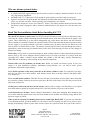
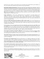
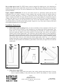
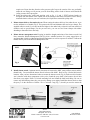
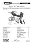
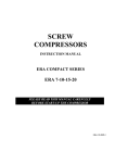
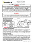
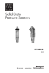
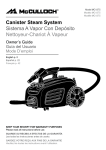
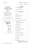
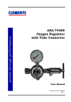
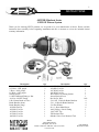
1
INSTRUCTIONS
#82235B Blackout Series
GM LSX Nitrous System
Thank you for choosing ZEX™ products; we are proud to be your manufacturer of choice. Please read this
instruction sheet carefully before beginning installation and take a moment to review the included limited
warranty information.
Description
Nitrous Management Unit
24" Hose, -3AN, purple
3' Hose, -4AN, purple
18' Hose, -4AN, purple
Nitrous Nozzle
1/8 NPT Bulkhead Fitting w/ Nut
-4 AN to 1/8 NPT Fitting
10lb. Nitrous Bottle w/Valve
Bottle Bracket (short)
Bottle Bracket (long)
.024 N20/Fuel Jet
.028 N20/ Fuel Jet
.032 N20/ Fuel Jet
.035 N20/ Fuel Jet
.040 N20/ Fuel Jet
Qty.
1
2
1
1
1
1
1
1
1
1
1
1
1
1
1
Description
.046 N20/ Fuel Jet
.054 N20/ Fuel Jet
.067 N20/ Fuel Jet
.083 N20/ Fuel Jet
Wire Harness w/Arming Switch
Aircraft Switch Cover
Red 18 GA. Wire
5/16-18 X 1" Bolt for Bottle Brackets
5/16 - 18 Nut for Bottle Brackets
5/16 Flat Washer
#8 x ½, Sheet Metal Screw
-4AN, 90 deg., Swivel Fitting
1/8-27 NPT Tap
TPS Resistor Wire
Schrader Valve Core Removal Tool
ZEX™
3418 Democrat Rd.
Memphis, TN 38118
Phone: 1-888-817-1008 Fax: (901) 375-3430
www.zex.com
Qty.
1
1
1
1
1
1
10 ft.
4
4
4
6
1
1
1
1
Part #ZEX211
Revised 12/12/08
2
Why our nitrous system is better:
•
•
•
•
A complete GM LSX engine platform specific nitrous system. Everything is included in this kit for a safe,
easy, plug and play installation.
Adjustable from 75-175 horsepower. Safe enough for stock engines, powerful enough for racing use.
System is activated at wide open throttle with advanced electronics that monitor your throttle position sensor
(TPS); easy and safe activation. Works especially well on throttle-by-wire vehicles.
Unique nozzle design has “Active Fuel Control™” built in. This feature monitors bottle pressure and when
the nitrous system is engaged, it adds or subtracts enrichment fuel so the engine never runs too rich or too
lean.
Read This Pre-installation Guide Before Installing Kit !!!!!!!
How the ZEX™ nitrous system works: The ZEX™ Part #82235B nitrous oxide injection system begins with a
connection to a supply cylinder containing pressurized liquid nitrous oxide and a connection to the engine’s fuel
system. These connections go to the nitrous management unit, which houses the nitrous and fuel solenoids.
These solenoids are normally closed but are opened when the TPS switch senses that the nitrous system is armed
and the engine is at wide-open throttle. Once these solenoids open, the nitrous and fuel are delivered to the
nitrous nozzle via flexible delivery lines. The amount of nitrous and fuel that is injected through the nozzle is
adjustable by means of metering jets installed in the nozzle itself. These metering jets allow for easy changes in
horsepower settings.
Work safely. Always wear eye protection and gloves when working with lines or hoses that contain pressurized
nitrous oxide or fuel. Never transport nitrous cylinders loose in a trunk or the back of a pick-up truck and
especially NOT within a vehicle's interior whether the cylinder is full OR empty. Always disconnect the
GROUND side of the battery when working on any electrical components.
Nitrous oxide won't fix problems you already have. Before you install your nitrous system, be sure your
engine is in good mechanical condition. Intermittent wiring problems, etc., can lead to erratic system
performance and possible engine damage.
Never defeat operation of the safety relief disc in the nitrous cylinder's valve. It's required by law and is
there for your safety. Never drill, machine, weld, deform, scratch, drop, or modify a nitrous oxide tank in ANY
way whatsoever!
Never overfill nitrous cylinders. That little bit extra will put you and others at risk of injury. More often than
not, when the cylinder warms up, the pressure goes above the limit of the safety relief disc and you lose all the
nitrous you just paid for.
All the power comes from the fuel, not the nitrous. Nitrous oxide is simply a tool that allows you to adjust
how much and how quickly the engine burns the fuel. If the fuel isn't there, the power won't be either.
Avoid detonation at all times. Nitrous enhanced detonation is much more damaging than detonation that
occurs when naturally-aspirated due to the increased amount of fuel available for releasing energy and the fact
that more oxygen is present.
When system is activated, if something doesn't feel or sound right, BACK OFF. If you hear any detonation
or feel anything unusual, get off the throttle. It's a lot easier to check everything over than it is to just try to drive
through it and damage expensive parts. Don't activate or have the system activated when you hit the stock rev
ZEX™
3418 Democrat Rd.
Memphis, TN 38118
Phone: 1-888-817-1008 Fax: (901) 375-3430
www.zex.com
Part #ZEX211
Revised 12/12/08
3
limiter. The stock rev limiter is a fuel cutoff. If you cut fuel while you're injecting nitrous, you're instantly very
lean. This momentary lean condition has the potential of causing engine damage.
Spark plugs and nitrous performance: The factory spark plugs are not suitable for use with nitrous. They are
designed with a particularly hot heat range and tend to cause a detonation condition after just a few seconds of
nitrous use. The solution to the problem is to install spark plugs that have a colder heat range and proper ground
strap design for nitrous use. ZEX™ has developed the ideal solution with nitrous specific spark plugs designed
just for nitrous using, daily driven performance vehicles. The ZEX™ V8 Performance Spark Plugs (Part#
82071-8 for a set of eight) have a heat range that has been optimized for nitrous but continues to have clean
firing performance for normal daily driving.
Engine modifications: If major engine modifications have been performed, a fuel pump upgrade will be
required for safe nitrous system operation. Major engine modifications would include turbochargers,
superchargers, aftermarket cylinder heads, head porting, camshafts, intake manifolds, etc. Failure to upgrade the
fuel system when using nitrous in these highly modified applications may cause serious lean conditions that can
result in severe engine damage.
Do not use Teflon sealing tape on any fittings in a ZEX™ nitrous system. It is easy for Teflon tape to get
pulled into the system, causing blockages that can ultimately lead to incorrect nitrous system performance and
potentially, engine damage. Only use liquid thread sealer for all NPT type fittings. Do not use any thread sealing
compound on AN style threads.
Do not attempt to start your engine if nitrous has been accidentally injected into the engine while it was
not running. If this occurs, disable all of the ignition coils by unplugging the leads going to them. Push the
accelerator pedal to wide open throttle and hold it there, push the clutch in, and with the throttle wide open,
engage the starter and turn over the engine for several seconds to clear the nitrous from the engine. Failure to do
this before attempting to restart the engine can lead to a dangerous intake system backfire.
Do not engage your nitrous system below 2500 rpm. This ensures that you will not have excessive cylinder
pressures that could cause engine damage. The ZEX™ Traction Control Window Switch (Part #82085) is ideal
for controlling the rpm range that your nitrous system operates in.
When finished using your nitrous system, close the nitrous bottle valve and relieve the line pressure. This
eliminates the possibility that nitrous could inadvertently accumulate in the intake manifold while the nitrous
system is not being used.
Do not run excessive bottle pressures. Excessive bottle pressures, over 1100psi, are dangerous to your engine.
Your ZEX™ nitrous system is calibrated and optimized to operate from 900-1000psi. Exceeding this will not
improve performance. Over 1100psi also runs the danger of locking the nitrous solenoid closed due to excessive
pressure working against the valve’s plunger. If this happens, you must cool the nitrous bottle down to lower the
pressure. This will allow the valve to operate properly again.
Start with the lowest horsepower setting and work your way up. This ensures if you have any tuning issues
to work out on your vehicle, they will get sorted out with a smaller shot of nitrous that will be less likely to
damage your engine. Once you have the car working well on the smaller shot, you can then safely start to step
up your nitrous kit horsepower.
Make sure your vehicle has an adequate fuel supply. Nitrous systems put a large demand on your vehicle’s
fuel system. Make sure you have a large enough fuel pump to handle the demands of your engine, as well as the
nitrous system.
ZEX™
3418 Democrat Rd.
Memphis, TN 38118
Phone: 1-888-817-1008 Fax: (901) 375-3430
www.zex.com
Part #ZEX211
Revised 12/12/08
4
How to adjust power levels: The ZEX™ nitrous system is designed for multiple power levels. Metering jets
installed in the nitrous nozzle control these power levels. To change the power output, all you need to do is
install the appropriate set of jets. The correct combination of jets is listed on the tune-up sheet on the back of this
instruction manual.
Engine computer modifications: Do not use the nitrous system if a non-nitrous custom tune has been
programmed into your engine’s computer. Custom computer tunes generally advance the ignition timing to
optimize non-nitrous horsepower. If nitrous is injected while these non-nitrous tunes are loaded into your
engine’s computer, detonation will occur and this can lead to severe engine damage. It is important to only use
computer tunes that have been specifically programmed for nitrous use. Specific tunes for nitrous should have
the ignition timing reduced, per the tune-up chart at the end of this instruction manual. It is generally
recommended that you retard the ignition timing around 2 degrees for every 50 hp worth of nitrous used, based
on an optimized ignition curve for your engine.
Installation Instructions
1. Decide where to put everything. Before you start to install the various components of this kit, you’ll
have to locate the best locations of each component by trial fitment and careful measurement. First,
decide where you want to mount the nitrous management unit. Remember, the stainless steel braided
lines that connect the NMU to the nitrous nozzle are 24 inches long. Next, observe and mark the
location on the air inlet ducting where you would like to put the nitrous nozzle; on most applications,
this is right between the MAF (mass airflow sensor) and the throttle body. The arming switch should be
installed in a position convenient to the driver, but not in an area where it could be accidentally armed.
Next, decide where and how you’ll mount the nitrous supply bottle, check Fig. 1, 2, 3, and 5 for
technical restrictions on bottle mounting locations and positions. Finally, have a reputable performance
shop fill your nitrous bottle with automotive grade nitrous oxide before you begin. Do not overfill the
nitrous bottle.
Fig. 1
Fig. 2
Fig. 3
2. Mount nitrous supply bottle
A. Mount the nitrous supply bottle in the trunk of the vehicle, with the outlet facing down. You may
want to consider installing a safety blow-down tube (ZEX™ Part #82099), as most racetracks
ZEX™
3418 Democrat Rd.
Memphis, TN 38118
Phone: 1-888-817-1008 Fax: (901) 375-3430
www.zex.com
Part #ZEX211
Revised 12/12/08
5
require one. Route the tube from the safety pressure relief cap to the exterior of the car, preferably
under the car. Doing so will prevent your car from filling with a cloud of nitrous oxide should the
safety pressure relief cap rupture.
B. Index the pickup tube with bottle position, refer to fig. 1, 2, and 3. ZEX™ nitrous bottles are
designed with the bottom of the siphon tube at the bottom of the bottle towards the outlet. Always
mount the bottle so that as your car accelerates, the liquid flows toward the pickup tube.
3. Mount nitrous delivery line under the car. When routing the nitrous delivery line under the car, try to
use the subframe as a conduit (Fig.5). This protects the line and eliminates the need to use clamps. The
supplied cable ties work if you can run the line higher in the under-body so that it's safe from road level
obstacles such as speed bumps. For the pro-race look, you can use steel loom clamps with rubber
sheathing to fasten the line to the body.
4. Mount nitrous management unit. Keeping in mind the length restrictions of the nitrous nozzle feed
lines, mount the Nitrous Management Unit (Fig.4) in a suitable location. It’s a pretty rugged piece of
equipment that is built to withstand underhood temperatures as well as exposure to weather. Connect the
nitrous delivery line to the Nitrous Management Unit.
NMU
Fig. 5
Fig. 4
5. Install nitrous nozzle. Optimum nozzle placement is between the MAF (mass airflow sensor) and the
throttle body. Do not install the nitrous nozzle in front of the MAF! Refer to Fig. 8 for the ideal nozzle
location. After you have determined where to mount the nitrous nozzle (Fig. 8), make sure this location
won’t interfere with other components. After you've found the spot, mark it and remove the air inlet
duct from your engine. Drill a 9/16 inch mounting hole and install the bulk head fitting. Be sure to
remove any drill shavings since they can severely damage your engine. Install the nitrous nozzle so that
the spray is in the direction of airflow. We’ve enclosed a tap (Fig. 7) should you need to mount the
ZEX™
3418 Democrat Rd.
Memphis, TN 38118
Phone: 1-888-817-1008 Fax: (901) 375-3430
www.zex.com
Part #ZEX211
Revised 12/12/08
6
nozzle in a metal duct. Just drill a 11/32 inch hole where you want to mount the nozzle, tap the hole and
install the nozzle. Once the nozzle is installed, place the appropriate tuning jets in the nozzle and attach
the 2-foot long, -3AN hoses to the nozzle jet fittings and the nitrous management unit (Fig.6).
6. Wire it.
A. Find a suitable place in the interior of the vehicle for the arming switch and drill a 1/2 inch (.500)
hole. Mount the switch and switch cover through this hole. Take the lead that the fuse assembly is
attached to and find a suitable 12 volt accessory source of power under the dash. Remember to
locate a power source that is capable of supplying at least 10 amps to the nitrous system. Use the Ttap electrical connector to splice into the 12 volt accessory wire and plug in the wire harness lead.
Take the other lead from the arming switch and connect it to the red wire from the Nitrous
Management Unit. As a reference for wire locations, use Fig. 8.
Fig. 8
B. Take the black wire that comes from the Nitrous Management Unit and attach it to a suitable chassis
ground. Remember to remove any paint at the attachment point to ensure a good ground.
C. Take the white wire from the NMU and connect it to the Throttle Position Sensor output voltage
wire. The correct TPS wire will have around .5 volts when the throttle blade is closed and around
4.5 volts when the throttle is opened fully. These are not exact voltage numbers, but simply give
you an idea of the proper voltage you should be seeing. Use the supplied red T-tap connector and
tap into the voltage output wire. Attach the red crimp-on blade connector to the white wire from the
Nitrous Management Unit and plug this wire into the T-tap.
ZEX™
3418 Democrat Rd.
Memphis, TN 38118
Phone: 1-888-817-1008 Fax: (901) 375-3430
www.zex.com
Part #ZEX211
Revised 12/12/08
7
IMPORTANT TECH NOTE FOR THROTTLE-BY-WIRE VEHICLES!
Due to the sensitivity of GM’s newer throttle by wire systems, the ZEX™ Nitrous
Management Unit may cause intermittent check engine lights on some vehicles if the
included TPS resistor wire is not used. If your vehicle has throttle-by-wire control, it is
recommended that you install the included white TPS resistor wire between the engine’s
Throttle Position Sensor (TPS) output wire and the white TPS wire going to the ZEX™
Nitrous Management Unit. Use of this resistor will effectively isolate the Nitrous
Management Unit and prevent check engine lights from occurring. This resistor in no
way affects the activation or performance of your ZEX™ nitrous system.
7. Program activation switch. Now that you have completed the wiring of your nitrous system, the next
step is to program the Activation Switch. To program the Activation Switch, turn the vehicle’s ignition
on, but do not start the engine. Turn the nitrous arming switch to the "ON" position. Go to the Nitrous
Management Unit (NMU) and locate the push-button switch. Depress, then release, the push-button
switch. Observe the NMU’s Operation Light. At this point, it should be RED. This RED light informs
you that the NMU’s Activation Switch is in learn mode. Return to the driver’s seat and depress the
accelerator pedal to the floor, holding it there for ten seconds. Release the accelerator pedal and go back
to the NMU and observe the Operation Light. At this point, the light should be flashing continuously
from RED to GREEN to OFF. This is the NMU’s way of telling you that it has successfully learned the
voltage curve of your engine’s throttle position sensor. Go back to the driver’s compartment and turn off
the system’s arming switch, then turn it back on. Go back to the NMU and observe the Operation Light.
It should be solid GREEN at this point. This informs you that the system is armed and ready to activate
at wide-open throttle. Return to the driver’s seat and depress and release the accelerator pedal several
times. You should hear the solenoids click each time you reach wide-open throttle. At this point, your
Activation Switch is fully programmed and ready for use. If you ever transfer your nitrous system to
another vehicle, perform this same procedure on the new vehicle to "relearn" the NMU’s Activation
Switch.
8. Install fuel delivery line.
WARNING!! The factory fuel system maintains fuel system pressure, even when the vehicle has
been shut off.
A. Before working on the vehicles fuel system, it is important to relieve the fuel system pressure. Refer
to the factory service manual for the proper procedure in doing this.
B. Once the fuel system’s pressure has been bled off, we are ready to work on the fuel connections for
the nitrous system. Most GM engines have a fuel pressure test port located on the factory fuel rail.
This provides a convenient place for us to tap into for the nitrous system’s fuel needs. First, locate
the fitting and verify that it matches the threads on the 3ft. long -4AN fuel feed line provided in the
nitrous kit. If everything checks-out, use the provided Schrader Valve Core Removal Tool to
unscrew and remove the core inside this test port fitting.
C. Attach one end of the -4 AN fuel line to the fuel pressure test port and attach the other end to the
Nitrous Management Unit’s fuel inlet.
9. Check fuel and nitrous pressure lines.
A. Perform a final inspection of all plumbing and electrical connections to ensure that they are correct.
B. Ensure that the nitrous bottle is turned off and the line pressure is relieved.
C. Start the engine and observe all fuel connections for any leaks. Fix any fuel leaks before proceeding.
D. Turn off the engine.
ZEX™
3418 Democrat Rd.
Memphis, TN 38118
Phone: 1-888-817-1008 Fax: (901) 375-3430
www.zex.com
Part #ZEX211
Revised 12/12/08
8
E. Open the nitrous bottle valve. Listen carefully for any leaks as your valve is opened. Leaks in the
nitrous supply line will be obvious because they will be covered in frost.
F. If everything checks out, close the nitrous bottle and relieve the line pressure.
10. Check fuel quality & ignition timing. The last thing to do before enjoying your new nitrous system is
to ensure that premium fuel (92 R/M Octane or better) is in the fuel tank and that your ignition timing is
programmed correctly. All recommended ignition timing retard amounts, in the Tune-Up Specs, are
calculated off of the base, stock ignition table. It is not recommended to go above 75hp without an ECU
reprogram, designed for nitrous. If the correct ignition timing program is not used for the higher
horsepower settings, severe engine damage may occur from detonation.
ZEX™ #82235B Nitrous System Tune-Up Specs
Nitrous Jet (950psi)
Fuel Jet (58psi)
Ignition Retard (deg.)
75 hp
40
24
0
100 hp
46
28
2
125 hp
54
32
4
150 hp
67
35
5
175 hp
83
40
6
Limited Warranty
ZEX™ warrants that all of its products are free from defects in material and workmanship, and against
excessive wear for a period of (1) one year from the date of purchase. This limited warranty shall cover the
original purchaser.
ZEX’s obligation under this warranty is limited to the repair or replacement of its product. To make a
warranty claim, the part must be returned within (1) one year of purchase to the address listed below, freight
prepaid. Items covered under warranty will be returned to you freight collect.
It is the responsibility of the installer to ensure that all of the components are correct before installation.
We assume no liability for any errors made in tolerances, component selection, or installation.
There is absolutely no warranty on the following:
A) Any parts used in racing applications;
B) Any product that has been physically altered, improperly installed or maintained;
C) Any product used in improper applications, abused, or not used in conjunction with the proper
parts.
There are no implied warranties of merchantability or fitness for a particular purpose. There are no
warranties, which extend beyond the description of the face hereof. ZEX™ will not be responsible for
incidental and consequential damages, property damage or personal injury damages to the extent permitted by
law. Where required by law, implied warranties or merchantability and fitness are limited for a term of (1) one
year from the date of original purchase.
This warranty gives you specific legal rights and you may also have other legal rights, which vary from state to
state.
ZEX™
3418 Democrat Rd.
Memphis, TN 38118
Phone: 1-888-817-1008 Fax: (901) 375-3430
www.zex.com
Part #ZEX211
Revised 12/12/08