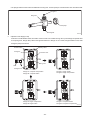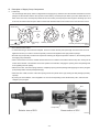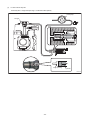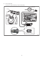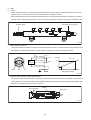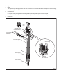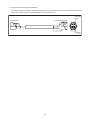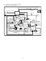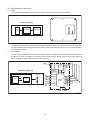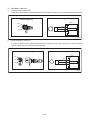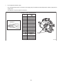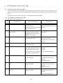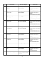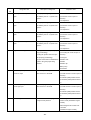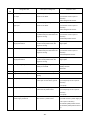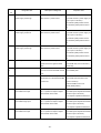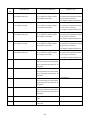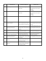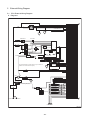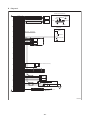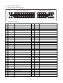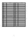
1
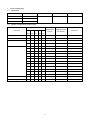
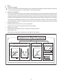
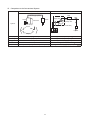
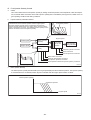
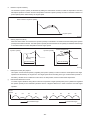
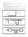
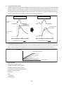
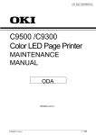
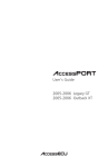
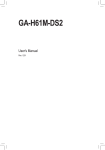
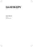
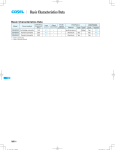
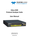
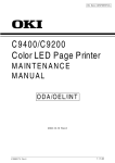
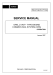
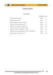
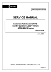
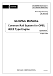
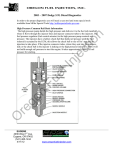
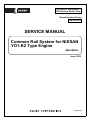
For DENSO Authorized
ECD Service Dealer Only
Diesel Injection Pump
No. E-03-01
SERVICE MANUAL
Common Rail System for NISSAN
YD1-K2 Type Engine
Operation
June, 2003
00400013E
Foreword
To meet the high pressurization requirements for the engine to deliver cleaner exhaust gas emissions, lower fuel
consumption and reduced noise, advanced electronic control technology is being adopted in the fuel injection system.
This manual covers the electronic control model Common Rail system with HP3 pump for the NISSAN YD1-K2 type
engine. Complex theories, special functions and components made by manufacturers other than DENSO are omitted
from this manual.
This manual will help the reader develop an understanding of the basic construction, operation and system configuration
of the DENSO manufactured components and brief diagnostic information.
TABLE OF CONTENTS
1. Product Application . . . . . . . . . . . . . . . . . . . . . . . . . . . . . . . . . . . . . . . . . . . . . . . . . . . . . . . . . . . . . . . . . . . . . . . . . . . . . . . . . . . . 1
1-1. Application . . . . . . . . . . . . . . . . . . . . . . . . . . . . . . . . . . . . . . . . . . . . . . . . . . . . . . . . . . . . . . . . . . . . . . . . . . . . . . . . . . . . . . . 1
1-2. System Components Parts Number . . . . . . . . . . . . . . . . . . . . . . . . . . . . . . . . . . . . . . . . . . . . . . . . . . . . . . . . . . . . . . . . . . . 1
2. Outline . . . . . . . . . . . . . . . . . . . . . . . . . . . . . . . . . . . . . . . . . . . . . . . . . . . . . . . . . . . . . . . . . . . . . . . . . . . . . . . . . . . . . . . . . . . . . . . 2
2-1. Features of System . . . . . . . . . . . . . . . . . . . . . . . . . . . . . . . . . . . . . . . . . . . . . . . . . . . . . . . . . . . . . . . . . . . . . . . . . . . . . . . . 2
2-2. Outline of System . . . . . . . . . . . . . . . . . . . . . . . . . . . . . . . . . . . . . . . . . . . . . . . . . . . . . . . . . . . . . . . . . . . . . . . . . . . . . . . . . . 4
3. Construction and Operation . . . . . . . . . . . . . . . . . . . . . . . . . . . . . . . . . . . . . . . . . . . . . . . . . . . . . . . . . . . . . . . . . . . . . . . . . . . . . 7
3-1. Description of Main Components . . . . . . . . . . . . . . . . . . . . . . . . . . . . . . . . . . . . . . . . . . . . . . . . . . . . . . . . . . . . . . . . . . . . . 7
3-2. Description of Control System Components . . . . . . . . . . . . . . . . . . . . . . . . . . . . . . . . . . . . . . . . . . . . . . . . . . . . . . . . . . 18
3-3. Various Types of Controls . . . . . . . . . . . . . . . . . . . . . . . . . . . . . . . . . . . . . . . . . . . . . . . . . . . . . . . . . . . . . . . . . . . . . . . . . . 22
4. DTC (Diagnosis Trouble Codes) Table . . . . . . . . . . . . . . . . . . . . . . . . . . . . . . . . . . . . . . . . . . . . . . . . . . . . . . . . . . . . . . . . . . . . 27
4-1. About the Codes shown in the table . . . . . . . . . . . . . . . . . . . . . . . . . . . . . . . . . . . . . . . . . . . . . . . . . . . . . . . . . . . . . . . . . 27
4-2. DTC (Diagnosis Trouble Code) Table . . . . . . . . . . . . . . . . . . . . . . . . . . . . . . . . . . . . . . . . . . . . . . . . . . . . . . . . . . . . . . . . . 27
5. External Wiring Diagram . . . . . . . . . . . . . . . . . . . . . . . . . . . . . . . . . . . . . . . . . . . . . . . . . . . . . . . . . . . . . . . . . . . . . . . . . . . . . . . 34
5-1. ECU External Wiring Diagram . . . . . . . . . . . . . . . . . . . . . . . . . . . . . . . . . . . . . . . . . . . . . . . . . . . . . . . . . . . . . . . . . . . . . . . 34
5-2. ECU Connector Diagram . . . . . . . . . . . . . . . . . . . . . . . . . . . . . . . . . . . . . . . . . . . . . . . . . . . . . . . . . . . . . . . . . . . . . . . . . . . 36
1. Product Application
1-1. Application
Vehicle Name
Vehicle Model
Engine Model
Exhaust Volume
Reference
PREMERA
ED
YD1-K2
2.2L
Made in France
ALMERA
HS
TINO
HM
1-2. System Components Parts Number
Applicable Model
Part Name
DENSO Part
Car Manufacturer
Number
Part Number
O
294000-0121
16700 AW401
O
095440-0420
17520 AW400
095000-5130
16600 AW400
100kW Engine
095000-5180
16600 BN800
82kW Engine
O
275800-2193
23710 AW402
Standard
O
275800-2203
23710 AW407
w/VDC
O
275800-2440
23710 AW410
w/ASCD
O
275800-2450
23710 AW415
w/ASCD, VDC
O
275800-2322
23710 BN811
Standard
O
275800-2332
23710 BN816
100kW Engine w/VDC
O
275800-2340
23710 BN800
82kW Engine
O
275800-2350
23710 BN805
82kW Engine w/VDC
O
275800-2363
23710 BU712
Standard
O
275800-2373
23710 BU717
100kW Engine w/VDC
O
275800-2380
23710 BU700
82kW Engine
O
275800-2390
23710 BU705
82kW Engine w/VDC
ED
HS
HS
HM
HM
100
100
82
100
82
Supply pump
O
O
O
O
Rail
O
O
O
O
Injector
O
O
O
O
Engine ECU
O
Crankshaft position sensor
O
O
O
O
O
949979-0090
23731 AW400
Cylinder recognition sensor
O
O
O
O
O
949979-1190
23731 AW410
-1-
Reference
2. Outline
2-1. Features of System
The common rail system was developed primarily to cope with exhaust gas regulations for diesel engines, and aimed for
1. further improved fuel economy; 2. noise reduction; and 3. high power output.
A. System Characteristics
The common rail system uses a type of accumulation chamber called a rail to store pressurized fuel, and injectors that
contain electronically controlled solenoid valves to spray the pressurized fuel into the cylinders. Because the engine ECU
controls the injection system (including the injection pressure, injection rate, and injection timing), the injection system is
unaffected by the engine speed or load. This ensures a stable injection pressure at all times, particularly in the low engine
speed range, and dramatically decreases the amount of black smoke ordinarily emitted by a diesel engine during startup and acceleration. As a result, exhaust gas emissions are cleaner and reduced, and higher power output is achieved.
a.
Injection Pressure Control
Enables high-pressure injection even at low engine speeds.
Optimizes control to minimize particulate matter and NOx emissions.
b.
Injection Timing Control
Enables finely tuned optimized control in accordance with driving conditions.
c.
Injection Rate Control
Pilot injection control sprays a small amount of fuel before the main injection.
-2-
B. Comparison to the Conventional System
-3-
2-2. Outline of System
A. Main System Components
-4-
B. Composition
The common rail system consists primarily of a supply pump, rail, injectors, and ECU.
C. Operation
a.
Supply Pump (HP3)
The supply pump draws fuel from the fuel tank, and pumps the high pressure fuel to the rail. The quantity of fuel discharged from the supply pump controls the pressure in the rail. The SCV (Suction Control Valve) in the supply pump
effects this control in accordance with the command received from the ECU.
b.
Rail
The rail is mounted between the supply pump and the injector, and stores the high-pressure fuel.
c.
Injector
This injector replaces the conventional injection nozzle, and achieves optimal injection by effecting control in accordance
with signals from the ECU. Signals from the ECU determine the length of time and the timing in which current is applied
to the injector. This in turn, determines the quantity, rate and timing of the fuel that is injected from the injector.
d.
Engine ECU
The engine ECU calculates data received from the sensors to comprehensively control the injection quantity, timing and
pressure, as well as the EGR (exhaust gas recirculation).
-5-
D. Fuel System
This system comprises the route through which diesel fuel flows from the fuel tank to the supply pump, via the rail, and
is injected through the injector, as well as the route through which the fuel returns to the tank via the overflow pipe.
E. Control System
In this system, the engine ECU controls the fuel injection system in accordance with the signals received from various
sensors. The components of this system can be broadly divided into the following three types: (a) Sensors; (b) ECU; and
(c) Actuators.
a.
Sensors
Detect the engine and driving conditions, and convert them into electrical signals.
b.
Engine ECU
Performs calculations based on the electrical signals received from the sensors, and sends them to the actuators in order
to achieve optimal conditions.
c.
Actuators
Operate in accordance with electrical signals received from the ECU. Injection system control is undertaken by electronically controlling the actuators. The injection quantity and timing are determined by controlling the duration and the timing
in which the current is applied to the TWV (Two-Way Valve) in the injector. The injection pressure is determined by controlling the SCV (Suction Control Valve) in the supply pump.
-6-
3. Construction and Operation
3-1. Description of Main Components
A. Supply Pump (HP3)
a.
Outline
The supply pump consists primarily of the pump body (eccentric cam, ring cam, and plungers), SCV (Suction Control
Valve), fuel temperature sensor, and feed pump.
The two plungers are positioned vertically on the outer ring cam for compactness.
The engine drives the supply pump at a ratio of 1:2. The supply pump has a built-in feed pump (trochoid type), and draws
the fuel from the fuel tank, sending it to the plunger chamber.
The internal camshaft drives the two plungers, and they pressurize the fuel sent to the plunger chamber and send it to
the rail. The quantity of fuel supplied to the rail is controlled by the SCV, using signals from the engine ECU. The SCV is
a normally opened type (the intake valve opens during de-energization).
-7-
b.
Supply Pump Exploded Diagram
-8-
c.
Supply Pump Internal Fuel Flow
The fuel that is drawn from the fuel tank passes through the route in the supply pump as illustrated, and is fed into the rail.
d.
Construction of Supply Pump
The eccentric cam is attached to the drive shaft. The eccentric cam is connected to the ring cam.
As the drive shaft rotates, the eccentric cam rotates in the eccentric state, and the ring cam moves up and down while
rotating.
-9-
The plunger and the suction valve are attached to the ring cam. The feed pump is connected to the rear of the drive shaft.
e.
Operation of the Supply Pump
As shown in the illustration below, the rotation of the eccentric cam causes the ring cam to push Plunger A upwards. Due
to the spring force, Plunger B is pulled in the opposite direction to Plunger A. As a result, Plunger B draws in fuel, while
Plunger A pumps it to the rail.
-10-
B. Description of Supply Pump Components
a.
Feed Pump
The trochoid type feed pump, which is integrated in the supply pump, draws fuel from the fuel tank and feeds it to the two
plungers via the fuel filter and the SCV (Suction Control Valve). The feed pump is driven by the drive shaft. With the rotation of the inner rotor, the feed pump draws fuel from its suction port and pumps it out through the discharge port. This
is done in accordance with the space that increases and decreases with the movement of the outer and inner rotors.
b.
SCV: Suction Control Valve
A linear solenoid type valve has been adopted. The ECU controls the duty ratio (the length of time that the current is
applied to the SCV), in order to control the quantity of fuel that is supplied to the high-pressure plunger.
Because only the quantity of fuel that is required for achieving the target rail pressure is drawn in, the actuating load of
the supply pump decreases.
When current flows to the SCV, variable electromotive force is created in accordance with the duty ratio, moving the armature to the left side. The armature moves the cylinder to the left side, changing the opening of the fuel passage and
thus regulating the fuel quantity.
With the SCV OFF, the return spring contracts, completely opening the fuel passage and supplying fuel to the plungers.
(Full quantity intake and full quantity discharge)
When the SCV is ON, the force of the return spring moves the cylinder to the right, closing the fuel passage (normally
opened).
By turning the SCV ON/OFF, fuel is supplied in an amount corresponding to the actuation duty ratio, and fuel is discharged by the plungers.
-11-
(1)
In case of short duty ON
Short duty ON => large valve opening => maximum intake quantity
-12-
(2)
In case of long duty ON
Long duty ON => small valve opening => minimum intake quantity
-13-
C. Rail
a.
Outline
Stores pressurized fuel (0 to 180 MPa) that has been delivered from the supply pump and distributes the fuel to each
cylinder injector. A rail pressure sensor and a pressure limiter are adopted in the rail.
The rail pressure sensor (Pc sensor) detects the fuel pressure in the rail and sends a signal to the engine ECU, while the
pressure limiter controls the fuel pressure in the rail. This ensures optimum combustion and reduces combustion noise.
b.
Rail Pressure (Pc) Sensor
This sensor detects fuel pressure in the rail and sends a signal to the ECU. It is a semi-conductor type pressure sensor
that utilizes the characteristic whereby electrical resistance changes when pressure is applied to silicon.
c.
Pressure Limiter (made by another manufacturer)
The pressure limiter relieves pressure by opening the valve if abnormally high pressure is generated. The valve opens
when pressure in the rail reaches approximately 200 MPa, and closes when pressure falls to approximately 50 MPa. Fuel
leaked by the pressure limiter returns to the fuel tank.
-14-
D. Injector
a.
Outline
The injectors inject the high-pressure fuel from the rail into the combustion chambers at the optimum injection timing,
rate, and spray condition, in accordance with commands received from the ECU.
b.
Characteristics
A compact, energy-saving solenoid-control type TWV (Two-Way Valve) injector has been adopted.
A hollow screw with a damper is fitted in the fuel leak pipe connection to improve the injection precision.
c.
Construction
-15-
d.
Operation
The TWV solenoid valve opens and closes the outlet orifice to control the pressure in the control chamber, and the start
and end of injection.
(1)
No injection
When no current is supplied to the solenoid, the spring force is stronger than the hydraulic pressure in the control chamber. Thus, the solenoid valve is pushed downward, effectively closing the outlet orifice. For this reason, the hydraulic
pressure that is applied to the command piston causes the nozzle spring to compress. This closes the nozzle needle,
and as a result, fuel is not injected.
(2)
Injection
When current is initially applied to the solenoid, the attraction of the solenoid pulls the TWV up, effectively opening the
outlet orifice and allowing the fuel to flow out of the control chamber. After the fuel flows out, the pressure in the control
chamber decreases, pulling the command piston up. This causes the nozzle needle to rise and injection to start.
The fuel that flows past the outlet orifice flows to the leak pipe and below the command piston. The fuel that flows below
the nozzle needle lifts the it upward, which helps to improve the nozzle's opening and closing response.
When current continues to be applied to the solenoid, the nozzle reaches its maximum lift, where the injection rate is also
at the maximum level. When current to the solenoid is turned OFF, the TWV falls, causing the nozzle needle to close
immediately and the injection to stop.
-16-
e.
Harness Connector with Correction Resistor
A correction resistor is provided in the harness connector (4-pin connector) of each injector to minimize the variances in
the injection volume among the cylinders (adjusted in the production line).
-17-
3-2. Description of Control System Components
A. Engine Control System Diagram
-18-
B. ECU (Electronic Control Unit)
a.
Outline
This is the command center that controls the fuel injection system and engine operation in general.
The EDU is contained inside the ECU. The EDU has been adapted to support the high-speed actuation of the injectors.
The high-speed actuation of the injector solenoid valve is made possible through the use of a high-voltage generating
device (DC/DC converter).
b.
EDU Operation
The high-voltage generating device converts the battery voltage into a high voltage. The Engine ECU sends signals to
terminals B through E of the EDU in accordance with the signals from the sensors. Upon receiving these signals, the
EDU outputs signals to the injectors from terminals H through K.
-19-
C. Description of Sensors
a.
Crankshaft Position Sensor (NE)
An NE pulsar attached to the crankshaft timing gear outputs a signal for detecting the crankshaft angle and engine speed.
b.
Cylinder Recognition Sensor (G)
A cylinder recognition sensor (G pulsar) is attached to the supply pump timing gear, and outputs a cylinder recognition
signal so that the ECU can calculate fuel injection timing.
-20-
c.
Fuel Temperature Sensor (THF)
The fuel temperature sensor is mounted on the supply pump, and detects the fuel temperature, sending a signal to the
engine ECU.
The detection component utilizes a thermistor.
-21-
3-3. Various Types of Controls
A. Outline
This system effects fuel injection quantity and injection timing control more appropriately than the mechanical governor
and timer used in the conventional injection pump. The engine ECU performs the necessary calculations in accordance
with the sensors installed on the engine and the vehicle. It then controls the timing and duration of time in which current
is applied to the injectors, in order to realize both optimal injection and injection timing.
a.
Fuel Injection Quantity Control Function
The fuel injection quantity control function replaces the conventional governor function. It controls the fuel injection to an
optimal injection quantity based on the engine speed and accelerator position signals.
b.
Fuel Injection Timing Control Function
The fuel injection timing control function replaces the conventional timer function. It controls the injection to an optimal
timing based on the engine speed and the injection quantity.
c.
Fuel Injection Rate Control Function
d.
Fuel Injection Pressure Control Function (Rail Pressure Control Function)
Pilot injection control injects a small amount of fuel before the main injection.
The fuel injection pressure control function (rail pressure control function) controls the discharge volume of the pump by
measuring the fuel pressure at the rail pressure sensor and feeding it back to the ECU. It effects pressure feedback control so that the discharge volume matches the optimal (command) value set in accordance with the engine speed and
the injection quantity.
-22-
B. Fuel Injection Quantity Control
a.
Outline
This control determines the fuel injection quantity by adding coolant temperature, fuel temperature, intake air temperature, and mass airflow corrections to the basic injection quantity that is calculated by the engine ECU, based on the engine operating conditions and driving conditions.
b.
Injection Quantity Calculation Method
c.
Basic Injection Quantity
The basic injection quantity is determined by the engine speed (NE) and the accelerator position. The injection quantity
is increased when the accelerator position signal is increased while the engine speed remains constant.
-23-
d.
Maximum Injection Quantity
The maximum injection quantity is calculated by adding the mass airflow correction, intake air temperature correction,
atmospheric pressure correction and the cold operation maximum injection quantity correction to the basic maximum injection quantity that is determined by the engine speed.
e.
Starting Injection Quantity
When the starter switch is turned ON, the injection quantity is calculated in accordance with the starting base injection
quantity and the starter ON time. The base injection quantity and the inclination of the quantity increase/decrease change
in accordance with the coolant temperature and the engine speed.
f.
Idle Speed Control (ISC) System
This system controls the idle speed by regulating the injection quantity in order to match the actual speed to the target
speed that is calculated by the engine ECU. The target speed varies according to the type of transmission (manual or
automatic), whether the air conditioner is ON or OFF, the shift position, and the coolant water temperature.
g.
Idle Vibration Reduction Control
To reduce engine vibrations during idle, this function compares the angle speeds (times) of the cylinders and regulates
the injection quantity for the individual cylinders if there is a large the difference, in order to achieve a smooth engine
operation.
-24-
C. Fuel Injection Timing Control
a.
Outline
Fuel injection timing is controlled by varying the timing in which current is applied to the injectors.
b.
(1)
Main and Pilot Injection Timing Control
Main Injection Timing
The engine ECU calculates the basic injection timing based on the engine speed the final injection quantity, and adds
various types of corrections in order to determine the optimal main injection timing.
(2)
Pilot Injection Timing (Pilot Interval)
Pilot injection timing is controlled by adding a pilot interval to the main injection timing. The pilot interval is calculated
based on the final injection quantity, engine speed, coolant temperature (map correction). The pilot interval at the time
the engine is started is calculated from the coolant temperature and speed.
c.
Injection Timing Calculation Method
(1)
Outline of Control Timing
(2)
Injection Timing Calculation Method
-25-
D. Fuel Injection Rate Control
While the injection rate increases with the adoption of high-pressure fuel injection, the ignition lag, which is the delay from
the start of injection to the beginning of combustion, cannot be shortened to less than a certain value. As a result, the
quantity of fuel that is injected until main ignition occurs increases, resulting in an explosive combustion at the time of
main ignition. This increases both NOx and noise. For this reason, pilot injection is provided to minimize the initial injection rate, prevent the explosive first-stage combustion, and reduce noise and NOx.
E. Fuel Injection Pressure Control
A value that is determined by the final injection quantity, the water temperature and the engine speed is calculated. During the starting of the engine, the calculation is based on the water temperature and the atmospheric pressure
F. Other Controls
Limit maximum injection quantity
Gradual acceleration injection quantity
Gradual deceleration injection quantity
Post-acceleration damping injection quantity
Reference injection quantity
Fuel cutoff
EGR
Turbo control
Glow plug relay
-26-
4
DTC (Diagnosis Trouble Codes) Table
4-1. About the Codes shown in the table
The "SAE" under the DTC code indicates the codes that are output when the STT (DST-1) is used, and the "Light" indicates the codes that are output when the CHECK ENGINE warning light is used. (SAE: Society of Automotive Engineers,
U.S.A.)
If multiple DTCs are output, they are shown in order starting with the lowest number.
4-2. DTC (Diagnosis Trouble Code) Table
*1: The area with *1 are purely vehicle side.
Code
Diagnostic Item
No.
U1000
CAN communication line
*1
Description of Diagnosis
Inspection Area
ECM cannot communicate with
Harness or connectors
other control units.
(CAN communication line is open or
ECM cannot communicate for more
shorted)
than the specified time.
P0016
Crankshaft position-camshaft posi-
The correlation between the crank-
Timing chain
tion correlation
shaft position sensor signal and
Signal plate
camshaft position sensor signal is
outside the normal range.
P0088
Fuel rail pressure too high
Fuel pressure is exessively higher
Fuel pump
than the specified value.
Harness or connectors
(The fuel pump circuit is open or
shorted.)
P0089
Fuel pump performance
Fuel pressure is too much higher
Fuel pump
than the target value.
P0093
Fuel system leak
"ECM detects a fuel system leak".
Fuel pump
(The relation between the output
Fuel rail
voltage to the fuel pump and the
Fuel pipe
input voltage from the fuel rail pres-
Fuel rail pressure relief valve
sure sensor is outside the normal
range.)
P0102
Mass airflow sensor circuit low input
Excessively low voltage from the
Harness or connectors
sensor to the ECM.
(The sensor circuit is open or
shorted.)
Mass airflow sensor
P0103
Mass airflow sensor circuit high
Excessively high voltage from the
Harness or connectors
input
sensor to the ECM.
(The sensor circuit is open or
shorted.)
Mass airflow sensor
P0112
Intake air temperature sensor circuit
Excessively low voltage from the
Harness or connectors
low input
sensor to the ECM.
(The sensor circuit is open or
shorted.)
Intake air temperature sensor
-27-
Code
Diagnostic Item
No.
P0113
Description of Diagnosis
Inspection Area
Intake air temperature sensor circuit
Excessively high voltage from the
Harness or connectors
high input
sensor to the ECM.
(The sensor circuit is open or
shorted.)
Intake air temperature sensor
P0117
Engine coolant temperature sensor
Excessively low voltage from the
Harness or connectors
circuit low input
sensor to the ECM.
(The sensor circuit is open or
shorted.)
Engine coolant temperature sensor
P0118
Engine coolant temperature sensor
Excessively high voltage from the
Harness or connectors
circuit high input
sensor to the ECM.
(The sensor circuit is open or
shorted.)
Engine coolant temperature sensor
P0122
Accelerator pedal position sensor 1
Excessively low voltage from the
Harness or connectors
circuit low input
APP sensor 1 to the ECM.
(The APP sensor 1 circuit is open or
shorted.)
Accelerator pedal position sensor
(Accelerator pedal position sensor
1)
P0123
Accelerator pedal position sensor 1
Excessively high voltage from the
Harness or connectors
circuit high input
APP sensor 1 to the ECM.
(The APP sensor 1 circuit is open or
shorted.)
Accelerator pedal position sensor
(Accelerator pedal position sensor
1)
P0182
Fuel pump temperature sensor cir-
Excessively low voltage from the
Harness or connectors
cuit low input
sensor to the ECM.
(The sensor circuit is open or
shorted.)
Fuel pump temperature sensor
P0183
Fuel pump temperature sensor cir-
Excessively high voltage from the
Harness or connectors
cuit high input
sensor to the ECM.
(The sensor circuit is open or
shorted.)
Fuel pump temperature sensor
P0192
Fuel rail pressure sensor circuit low
Excessively low voltage from the
Harness or connectors
input
sensor to the ECM.
(The sensor circuit is open or
shorted.)
Fuel rail pressure sensor
P0193
Fuel rail pressure sensor circuit high
Excessively high voltage from the
Harness or connectors
input
sensor to the ECM.
(The sensor circuit is open or
shorted.)
Fuel rail pressure sensor
P0200
Fuel injector power supply circuit
ECM detects an excessively high/
low voltage from the fuel injection
power source.
-28-
ECM
Code
Diagnostic Item
No.
P0201
Description of Diagnosis
Inspection Area
No. 1 cylinder fuel injector circuit
An improper voltage signal is sent to
Harness or connectors
open
the ECM by the No. 1 cylinder fuel
(The sensor circuit is open or
injector.
shorted.)
Fuel injector #1
P0202
No. 2 cylinder fuel injector circuit
An improper voltage signal is sent to
Harness or connectors
open
the ECM by the No. 2 cylinder fuel
(The sensor circuit is open or
injector.
shorted.)
Fuel injector #2
P0203
No. 3 cylinder fuel injector circuit
An improper voltage signal is sent to
Harness or connectors
open
the ECM by the No. 3 cylinder fuel
(The sensor circuit is open or
injector.
shorted.)
Fuel injector #3
P0204
No. 4 cylinder fuel injector circuit
An improper voltage signal is sent to
Harness or connectors
open
the ECM by the No. 4 cylinder fuel
(The sensor circuit is open or
injector.
shorted.)
Fuel injector #4
P0217
Engine overheating
Cooling fan does not operate prop-
Harness or connectors
erly (overheating).
(The cooling fan circuit is open or
Cooling fan system does not oper-
shorted.)
ate properly (overheating).
Cooling fan
Engine coolant was not added to the
Radiator hose
system using the proper filling
Radiator
method.
Radiator cap
Water pump
Thermostat
P0222
Accelerator pedal position sensor 2
Excessively low voltage from the
Harness or connectors
circuit low input
APP sensor 2 to the ECM.
(The APP sensor 2 circuit is open or
shorted.)
Accelerator pedal position sensor
(Accelerator pedal position sensor
2)
P0223
Accelerator pedal position sensor 2
Excessively high voltage from the
Harness or connectors
circuit high input
APP sensor 2 to the ECM.
(The APP sensor 2 circuit is open or
shorted.)
Accelerator pedal position sensor
(Accelerator pedal position sensor
2)
P0234
Turbocharger overboost condition
ECM detects excessively high turbo- Turbocharger
charger boost pressure.
Vacuum hose (YD22DDTi engine
models)
Turbocharger boost control solenoid valve
(YD22DDTi engine models)
-29-
Code
Diagnostic Item
No.
P0237
Description of Diagnosis
Inspection Area
Turbocharger boost sensor circuit
Excessively low voltage from the
Harness or connectors
low input
sensor to the ECM.
(The sensor circuit is open or
shorted.)
Turbocharger boost sensor
P0238
Turbocharger boost sensor circuit
Excessively high voltage from the
Harness or connectors
high input
sensor to the ECM.
(The sensor circuit is open or
shorted.)
Turbocharger boost sensor
P0335
Crankshaft position sensor circuit
Crankshaft position sensor signal is
Harness or connectors
not detected by the ECM when the
(The sensor circuit is open or
engine is running.
shorted.)
Crankshaft position sensor
P0336
Crankshaft position sensor circuit
Crankshaft position sensor signal is
Crankshaft position sensor
range/performance
not the normal pattern when the
Signal plate
engine is running.
P0340
Camshaft position sensor circuit
Camshaft position sensor signal is
Harness or connectors
not detected by the ECM when the
(The sensor circuit is open or
engine is running.
shorted.)
Camshaft position sensor
P0341
Camshaft position sensor circuit
Camshaft position sensor signal is
Camshaft position sensor
range/performance
not the normal pattern when the
Signal plate
engine is running.
P0563
Battery voltage high
Excessively high voltage from the
Battery
battery to the ECM.
Battery terminal
Alternator
P0605
Engine control module (ROM)
ECM ROM is malfunctioning.
ECM
P0606
Engine control module (Processor)
ECM calculation function is malfunc- ECM
tioning.
P0628
Fuel pump control circuit low input
ECM detects a fuel pump control cir- Harness or connectors
cuit is open or short to the ground.
(The fuel pump circuit is open or
shorted.)
Fuel pump
P0629
Fuel pump control circuit high input
ECM detects a fuel pump control cir- Harness or connectors
cuit is short to power source.
(The fuel pump circuit is open or
shorted.)
Fuel pump
P0642
Accelerator pedal position sensor 1
ECM detects an excessively low
Harness or connectors
power supply circuit low
APP sensor 1 power source.
(The APP sensor 1 power supply circuit is open or shorted.)
Accelerator pedal position sensor
(Accelerator pedal position sensor
1)
-30-
Code
No.
P0643
Diagnostic Item
Description of Diagnosis
Inspection Area
Accelerator pedal position sensor 1
ECM detects an excessively high
Harness or connectors
power supply circuit high
APP sensor 1 power source.
(The APP sensor 1 power supply circuit is open or shorted.)
Accelerator pedal position sensor
(Accelerator pedal position sensor
1)
P0652
Accelerator pedal position sensor 2
ECM detects an excessively low
Harness or connectors
power supply circuit low
APP sensor 2 power source.
(The APP sensor 2 power supply circuit is open or shorted.)
Accelerator pedal position sensor
(Accelerator pedal position sensor
2)
P0653
Accelerator pedal position sensor 2
ECM detects an excessively high
Harness or connectors
power supply circuit high
APP sensor 2 power source.
(The APP sensor 2 power supply circuit is open or shorted.)
Accelerator pedal position sensor
(Accelerator pedal position sensor
2)
P0686
P1211
ECM relay circuit
TCS control unit
*1
ECM detects ECM relay is stuck
Harness or connectors
closed even if the ignition switch
(The ECM relay circuit is shorted.)
OFF.
ECM relay
ECM received malfunction informa-
ESP/TCS/ABS control unit
tion from the ESP/TCS/ABS control
TCS related parts
unit.
P1212
TCS communication line
*1
ECM cannot continuously receive
Harness or connectors
information from the ESP/TCS/ABS
(The CAN communication line is
control unit.
open or shorted.)
ESP/TCS/ABS control unit
Dead (Weak) battery
P1260
No. 1 cylinder fuel injector adjust-
Excessively low voltage from the
Harness or connectors
ment resistor low input
No. 1 cylinder fuel injector adjust-
(The fuel injector adjustment resistor
ment resistor to the ECM.
circuit is open or shorted.)
Fuel injector adjustment resistor #1
P1261
No. 1 cylinder fuel injector adjust-
Excessively high voltage from the
Harness or connectors
ment resistor high input
No. 1 cylinder fuel injector adjust-
(The fuel injector adjustment resistor
ment resistor to the ECM.
circuit is open or shorted.)
Fuel injector adjustment resistor #1
P1262
No. 3 cylinder fuel injector adjust-
Excessively low voltage from the
Harness or connectors
ment resistor low input
No. 3 cylinder fuel injector adjust-
(The fuel injector adjustment resistor
ment resistor to the ECM.
circuit is open or shorted.)
Fuel injector adjustment resistor #3
-31-
Code
No.
P1263
Diagnostic Item
Description of Diagnosis
Inspection Area
No. 3 cylinder fuel injector adjust-
Excessively high voltage from the
Harness or connectors
ment resistor high input
No. 3 cylinder fuel injector adjust-
(The fuel injector adjustment resistor
ment resistor to the ECM.
circuit is open or shorted.)
Fuel injector adjustment resistor #3
P1264
No. 4 cylinder fuel injector adjust-
Excessively low voltage from the
Harness or connectors
ment resistor low input
No. 4 cylinder fuel injector adjust-
(The fuel injector adjustment resistor
ment resistor to the ECM.
circuit is open or shorted.)
Fuel injector adjustment resistor #4
P1265
No. 4 cylinder fuel injector adjust-
Excessively high voltage from the
Harness or connectors
ment resistor high input
No. 4 cylinder fuel injector adjust-
(The fuel injector adjustment resistor
ment resistor to the ECM.
circuit is open or shorted.)
Fuel injector adjustment resistor #4
P1266
No. 2 cylinder fuel injector adjust-
Excessively low voltage from the
Harness or connectors
ment resistor low input
No. 2 cylinder fuel injector adjust-
(The fuel injector adjustment resistor
ment resistor to the ECM.
circuit is open or shorted.)
Fuel injector adjustment resistor #2
P1267
No. 2 cylinder fuel injector adjust-
Excessively high voltage from the
Harness or connectors
ment resistor high input
No. 2 cylinder fuel injector adjust-
(The fuel injector adjustment resistor
ment resistor to the ECM.
circuit is open or shorted.)
Fuel injector adjustment resistor #2
P1268
No. 1 cylinder fuel injector
The valve built into No. 1 cylinder
Fuel injector #1
fuel injector does not close properly
(stuck open) when the injector is not
energized.
P1269
No. 2 cylinder fuel injector
The valve built into No. 2 cylinder
Fuel injector #2
fuel injector does not close properly
(stuck open) when the injector is not
energized.
P1270
No. 3 cylinder fuel injector
The valve built into No. 3 cylinder
Fuel injector #3
fuel injector does not close properly
(stuck open) when the injector is not
energized.
P1271
No. 4 cylinder fuel injector
The valve built into No. 4 cylinder
Fuel injector #4
fuel injector does not close properly
(stuck open) when the injector is not
energized.
P1272
Fuel rail pressure relief valve open
Fuel rail pressure relief valve is
Fuel rail pressure relief valve
open.
P1273
Fuel pump insufficient flow
ECM detects an abnormal fuel pressure pulse.
-32-
Fuel pump
Code
Diagnostic Item
No.
P1274
Fuel pump protection
Description of Diagnosis
Inspection Area
Fuel pressure much higher than the
Harness or connectors
target value.
(The fuel pump circuit is open or
shorted.)
Fuel pump
P1275
Fuel pump exchange
Fuel pressure much higher than the
Harness or connectors
target value.
(The fuel pump circuit is open or
shorted.)
Fuel pump
P1610
Immobi. related
-1612,
P1614
-1617
*1
P2135
"Accelerator pedal position sensor 1,
The correlation between the APP
Harness or connectors
2 signal correlation"
sensor 1 signal and APP sensor 2
(The APP sensor circuit is open or
signal is outside the normal range.
shorted.)
Accelerator pedal position sensor
P2146
No. 1 and 4 cylinder fuel injector
Improper voltage signal sent to the
Harness or connectors
power supply circuit open
ECM by the No. 1 and 4 cylinder fuel
(The fuel injector circuit is open.)
injectors.
P2147
P2148
P2149
Fuel injector circuit low input
ECM detects the fuel injector circuit
Harness or connectors
is shorted to the ground.
(Fuel injector circuit shorted.)
ECM detects the fuel injector circuit
Harness or connectors
is shorted to the power source.
(Fuel injector circuit shorted.)
No. 2 and 3 cylinder fuel injector
Improper voltage signal is sent to
Harness or connectors
power supply circuit open
the ECM by the No. 2 and 3 cylinder
(The fuel injector circuit is open.)
Fuel injector circuit high input
fuel injectors.
P2228
Barometric pressure sensor circuit
Excessively low voltage from the
low input
barometric pressure sensor (built-
ECM
into ECM) to the ECM.
P2229
Barometric pressure sensor circuit
Excessively high voltage from the
high input
barometric pressure sensor (builtinto ECM) to the ECM.
-33-
ECM
5
External Wiring Diagram
5-1. ECU External Wiring Diagram
A. Diagram 1
-34-
B. Diagram 2
-35-
5-2. ECU Connector Diagram
A. ECU Connector Terminal Layout
B. Terminal Connections
No.
Pin Symbol
Connections
No.
1
P-GND
POWER GROUND
31
2
P-GND
POWER GROUND
32
3
P-GND
POWER GROUND
33
4
COMMON 1 INJECTION COMMON
34
5
COMMON 1 INJECTION COMMON
35
6
VNT
36
EVRV FOR VNT
Pin Symbol
Connections
37
38
39
10
SCV+
SUCTION CONTROL VALVE
40
TWV3
INJECTION DRIVE 3
11
41
TWV3
INJECTION DRIVE 3
12
42
TWV1
INJECTION DRIVE 1
13
43
TWV1
INJECTION DRIVE 1
14
44
A-VCC3
SENSOR (POWER SUPPLY)
15
45
A-VCC4
SENSOR (POWER SUPPLY)
16
46
NE+
CRANKSHAFT POSITION SENSOR+
17
47
G+
CYLINDER RECOGNITION SENSOR+
18
48
PFUEL
RAIL PRESSURE SENSOR
19
49
PFUEL
RAIL PRESSURE SENSOR
20
50
THF
FUEL TEMP
21
TWV4
INJECTION DRIVE 4
51
THW
COOLANT TEMP
22
TWV4
INJECTION DRIVE 4
52
BOOST
BOOST SENSOR
23
TWV2
INJECTION DRIVE 2
53
24
TWV2
INJECTION DRIVE 2
54
AMF
AMF SENSOR
25
EGR#1
STEP MOTOR A
55
EXT-A-TMP
EXT-AIR-TEMP-SENSOR
26
EGR#2
STEP MOTOR B~
56
27
EGR#3
STEP MOTOR A~
57
28
EGR#4
STEP MOTOR B
58
29
SCV-
SUCTION CONTROL VALVE
59
RINJ1
INJECTOR CORRECTION 1
60
RINJ2
INJECTOR CORRECTION 2
30
-36-
No.
Pin Symbol
Connections
No.
Pin Symbol
61
RINJ3
INJECTOR CORRECTION 3
92
62
RINJ4
INJECTOR CORRECTION 4
93
63
A-VCC5
SENSOR (POWER SUPPLY)
94
64
A-VCC6
SENSOR (POWER SUPPLY)
95
65
NE-
ENGINE SPEED SENSOR-
96
66
G-
CRANKSHAFT POSITION SENSOR-
97
67
S-GND
SHIELD GROUND
98
68
PFUELRTN
SENSOR GROUND
99
69
THFRTN
FUEL TEMP RTN
100 BRK1
70
THWRTN
COOLANT TEMP RTN
101
71
BOOSTRTN
BOOST SENSOR RTN
102
72
EGRLIFTRTN
EGR LIFT SENSOR RTN
103
73
AMFRTN
AMF RTN
104
74
EXT-A-RTN
EXT-AIR-TEMP-SENSOR RTN
105 M-REL
Connections
APS2GND
SENSOR GROUND
CAN1-H
CAN COMMUNICATION
STA-SW
STARTER SW
BRAKE SW1
MAIN RELAY
75
106
76
107 IG-SW
IGNITION SW
77
108 IG-SW
IGNITION SW
78
A-GND
INJECTOR CORRECTION RTN
109
79
AD5
ANALOG INPUT OPTION
110
N-SW
NEUT SW
80
AD6
ANALOG INPUT OPTION
111
PS-SW
POWER STRG SW
81
AD7
ANALOG INPUT OPTION
112
82
A-VCC1
SENSOR (POWER SUPPLY)
113
M-REL
MAIN RELAY
83
APS1
ACCEL PEDAL SENSOR
114
C-GND
SIGNAL GROUND
84
APS1GND
SENSOR GROUND
115
85
S-GND
SHIELD GROUND(APS)
116
+BP
BATTERY+ (MAIN RELAY)
86
87
117
CAN1-L
CAN COMMUNICATION
88
118
119
89
K-LINE
KWP2000 K-LINE
120 +BP
BATTERY+ (MAIN RELAY)
90
A-VCC2
SENSOR (POWER SUPPLY)
121 BATT
BATTERY+
91
APS2
ACCEL PEDAL SENSOR
-37-
Published: June 2003
Duplication prohibited without permission
Edited and published by:
Service Department, DENSO Corporation
1-1 Showa-cho, Kariya, Aichi Prefecture, Japan
[DTP]