1
SEAGATE ThCHNOLOGY
ST-506 MICROWINCHESfER
SERVICE MANUAL
MAY 1, 1982
360 El Pueblo Road
Scotts Valley, CA
95066
Phone(408)438-6550
TABLE CF <XNIENTS
SEO]CN
1.0
2.0
I~~Irn..................................................
•• 1
1.1
General Description ••••••••••••••••••••••• ~ •••••••••••••• 1
1.2
Specification Sunnary •••••••••••••••••••••••••••••••••••• 2
1.2 • 1
Phy sic al •• " "
1.2.2
Reliability ••••••••••••••••••••••••••••••••••••••• 2
1.2 • 3
Per f ormanc e ••••••••••••••••••••••••••••••••••••••• 3
1.2.4
Functional •••••••••••••••••••••••••••••••••.••••••• 3
~ y G'
2.1
"""
e e e
'" .. '" '" .. '" '" '"
2
CPERA.TICN'S •••••••••••••••••••••••••••••••••••••••••• 4
General •...•..••.•.•.••••...•.•......••...•...•.••.••.•.• 4
2.1.1
Recording Format •••••••••••••••••••••••••••••••••• 4
2 .1.2
Tr ack Format ••••••••••••••••••••••••••••••• " •••••• 4
2.1.3
Winchester Heads •••••••••••••••••••••••••••••••••• 6
2.1.4
Discs
2.1.5
Air Filtration Systern••••••••••••••••••••••••••••• 6
6
2.2 Mechanical Theory •••••••••••••••••••••••••••••••••••••••• 7
2.3
~
2.1.1
Track
Sensor •••••••••••••••••••••••••••••••••••.• 7
2.2.2
Index Sensor •••••••••••••••••••••••••••••••••••••• 7
2.2.3
Ground Spr ing ••••••••••••••••••••••••••••••••••••• 7
2.2.4
Spindle Brake .......•....•.......................• 8
Electrical Theory/Flowchart •••••••••••••••••••••••••••••• 9
2.3.1 Motor Speed Control ••••••••••••••••••••••••••••••• 9
2.3.2
Auto Recalibration ••••••••••••••••••••••••••••••• 11
2.3.3
Drive Selection •••••••.•••••••••••••••••••••••••• 13
TABLE CE a:NIENTS
SEO]CN
2.3.4
Step (peration ••••••••••••••••••••••••••••••••••• 14
2.3.5
Read Cperation ••••••••••••••••••••••••••••••••••• 17
2.3.6 Write Cperation •••••••••••••••••••••••••••••••••• 19
3. 0
2.4
Test Point Description••••••••••••••••••• , •••••••••••••• 22
2 •5
Sch ana tic s • • • • • • • • • • • • • • • • • • • • • • • • • • • • • • • • • • • • • • • • • • • • • • 2 8
~I~<:E/REI>AIR ••••••••••••••••••••••••••••••••••••••••••• 34
3.1
Introduction•••••••••••••••••••••••••••••••••••••••••••• 34
3.2
Rexnovals And Adjusttnents •••••••••••••••••••••••••••••••• 35
3.2.1 Main Control P.C.B ••••••••••••••••••••••••••••••• 35
3.2.2 Motor Control P.C.B •••••••••••••••••••••••••••••• 35
4.0
3.2.3
Spindle Brake •••••••••••••••••••••••••••••••••••• 36
3.2.4
Index Sensor ••••••••••••••••••••••••••••••••••••• 36
3.2.5
Ground Spring •••••••••••••••••••••••••••••••••••• 37
3.2.6
Track
3 .2 • 7
Fr on t Cover •••••••••••••••••••••••••••••••••••••• 3 8
3.2.8
Front Cover LED•••••••••••••••••••••••••••••••••• 38
3.2.9
Side Franles •••••••••••••••••••••••••••••••••••••• 38
~
Sensor ••••••••••••••••••••••••••••••••••• 37
ILLUSTRATED PARTS CATALOG•••••••••••••••••••••••••••••••••••• 40
4.1
4.2
Physical Locations •••••••••••••••••••••••••••••••••••••• 40
4.1.1
Drive Exploded View•••••••••••••••••••••••••••••• 41
4.1.2
Connectors Exploded View••••••••••••••••••••••••• 42
Carr~onent
Locations ••••••••••••••••••••••••••••••••••••• 43
ii
TABLE OF c:INIFNrS
SEO]CN
4.2.1 Main COntrol p.e.B.
PfiN 20019 ••••••••••••••••••• 44
4.2.2 Main COntrol P.C.B.
PIN 20040 ••••••••••••••••••• 45
4.2.3
Motor Control P.C.B.
P/;N 20003 •••••••••••••••••• 46
4.3.1 Main Control P .C.B.
PjN 20019 ••••••••••••••••••• 48
4.3.2 Main Control P .C.B.
PIN 20040 ••••••••••••••••••• 50
4.3.3
Motor Control P .C.B.
4.3.4
Spare Parts List ••••••••••••••.•••••••••.•••••••• 53
PIN 20003 •••••••••••••••••• 52
iii
LIST CF ILllSTRATICNS
FIGlRE
2.1
Tt ack Format •••••••••••••••••••••••••••• ~ ••••••••••••••••••••• 5
2.2
Test Point 1 Tim.ing •••••••••••••••••"-• ••.••• eo • • • • • • ~ ~ • • • • • • • • • • 24
2.3
Test Point 2 Tilning •••••••••••••••••••••••••••••••••••••••••• 24
2.4
Test Point 4 Tim.i ng •••••••••••••••••••••••••••••••••••••••••• 24
2.5
Test Point 5 Tilning •••••••••••••••••••••••••••••••••••••••••• 24
2.6
Test Point 7 and 8 Tim.ing •••••••••••••••••••••••••••• '••••• ••• 25
2.7
Test Point 11 and 13 Tilning •••••••••••••••••••••••••••••••••• 25
2.8
Tes t Point Layout
p.e.B.
P~
20019 •••••••••••••••••••••••• 26
2.9
Tes t Point Layout - P .C.B.
PIN
20040 •••••••••••••••••••••••• 27
LIST CF TABLES
~
TABLE
2.1
Step Pulse Encoding/Phase Sequencing ••••••••••••••••••••••••• 16
iv
ST-506 Service Manual
Introduction
1.0
INTRODUcnON
1.1
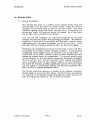
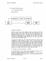
General Description
The ST-506 disc drive is a random access storage device with two
non-fcmovable 5 i/4 inch discs as storage media. Each disc surface
emplQYs one moveable head to service 153 data tracks. The total
formatted capacity of the four he ads and surf ac es is 5 meg abyt es (32
sectors per track, 256 bytes per sector, 612 tracks). Up to four drives
may be daisy chain connected in one system.
Low cost and unit reliability are achieved through the use of a band
actuator and open loop stepper head positioning mechanism. The inherent
simplicity of m.echanical construction and electronic controls allows
maintenance free operation throughout the life of the drive. Both
electronic PCB's are mounted outside the HDA for field serviceability.
Mechanical and contamination protection for the heads, actuator and discs
are provided by an impact resistant aluminum enclosure. A self contained
recirculating system supplies clean air through a 0.3 micron filter. A
second port in the filter assembly allows pressure equalization with
ambient air without chance of contamination. A patented spindle pump
aSSUf es adequate air flow and uniform temperature distribution throughout
the head and disc area. Therm.al isolation of the stepper and spindle
motor assemblies from the disc enclosure yields a very low temperature
rise within the enclosure, providing significantly greater off-tr ack margin
and the ability to immediately perform read and write operations after
power up with.nothermal stabilization delay.
The ST-506 electrical interface is similar to the Shugart Associates
SA1000 family of 8 inch fixed disc drives. The ST-506 size and mounting
ar e id en tic al to the industry standard minifloppy disc drives and uses the
same DC voltage and connector. No AC power is required.
Seagate Technology
PAGE 1
5/1/82
Sf-506 Service Manual
Introduction
1.2
Specification Summary
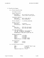
1.2.1
Physical Specifications
Environmental Lnnits
Ambient Temperature:
Ci>erating =
Non-operating =
400 to 122 0 F (4 0 to 50 0 C)
-40 0 to 140 0 F (-40 0 to 60 0 C)
Temperature Gradient:
'18 0 F / Hour (10 0 C)
Operating =
Non-operating = Below condensation
ReI at ive HlIl1idi ty
=
8 to 80% Non-condensing
Maximun el evat ion:
Operating =
Non-operating
Shock:
<»erating
=
=
r-~on-opelati.ng
10,000 Feet
-1000 to 30,000 Feet
,lOG's (On side frames)
:::
D.C. Power Requiranents:
+12V ±5%, 1.8A Typical,4.5A At power on
+5V ±5%" .7A Typical, 1.0A Maximum
Maximun Ripple = 50mv peak to peak (12V, 5V)
Mechanical Dimens ions:
Height =
3.25 Inches
Width =
5.75 Inches
Depth =
8.00 Inches
4.6 Pounds (2.1Kg)
'¥eight =
Shipping Vleight = 7.0 Pounds (3.2Kg)
Heat Dissipation:
Typical =
Maxinulm
1.2.2
=
25 Watts
29 Watts
Reliability Specifications
=
11,000 PCH, Typical usage
30 Minutes
Not required
Component design life = 5 Years'
NITBF
MI1R
P,M: =
Seagate Technology
=
PAGE 2
5/1/82
Introduction
Sf-506 Service Manual
Error Rates:
Soft Read Errors =
Hard Read Errors* =
Seek Error s =
1 per 10 10 bits read
1 per 10 12 bits read
1 per 10 6 seeks
*Not recoverable within 16 retries
1.2.3
Perfonnance Specifications
Capaci ty
Unf orma t ted:
Per Drive =
Per Sur f ace =
Per Track =
6.38 Megabytes
1 • 59 Meg aby t es
10416 Bytes
Formatted:
Per Drive =
Per Surface =
Per Track =
Per Sector =
Sectors per Track
5 .0 Meg aby t es
1.25 Megabytes
8192 Bytes
=
Acces s Time:
Track to Track =
Avera.ge* =
lv1ax imum* * =
Set tl ing Time =
256 Bytes
32
3 milliseconds
170 mill i seconds
500 milliseconds
15 milliseconds typical
*Reducible to 85 IDS using fast seek algorithm
*Reducible to 205 IDS using fast seek algorithm
1.2.4
Transfer Rate:.
5.0 Megabits per second
Average Latency:
8.33 milliseconds
Functional Specifications:
Rotational Speed =
Recording Density =
Flux Dens i ty =
Track Density =
Cyl iode! s =
Tracks =
ReadfWrite Heads =
Di scs =
Seagate Technology
3600 RPM ±1%
7690 BPI Maximum
7690 FeI 1vlax imum
255 TIl
153
612
4
2
PAGE 3
5/1/82
Theory of Oper ations
2.0
ST-506 Servic e Manual
THEORY OF OPERATIONS
2.1
General
2.1.1
Recording Format
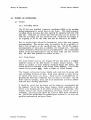
The ST-506 uses modified frequency modulation (MFM) as the encoding
method implemented to record data on the drive. This double-density
encoding scheme increases disc data capacity by replacing clock bits with
data bits. Clock bits are written only when data bits are not pr es ent in
both the preceding and the current bit cell. Clock bits are written at
the beginning of the bit cell, while data bi~s are written in the middle.
Due to predictable bit-shift- phenomena, write data may require
precompensatiori. This function must be provided by the controller to
insure data integrity at the specified error rate. The Sf-506 requires
precompensation of write data on cylinders 128 through 152. The data
pattern determines which bits must be precompensated. The recommended
amount of this precompensation is 12ns for both early and late written
bits. All other data patterns are written on time.
2.1.2
Track Format
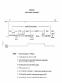
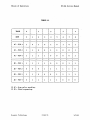
The track format used on the Seagate ST-506 disc drive is a slightly
modified version of the IBM System 34 double density format. This
format is common to many industry standard floppy disc drives. All
ST-506 drives are formatted at the factory before shipping. Data fields
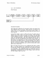
contain the bit pattern UJL Refer to Figure-2.1 (Track Format).
The Seagate soft-sector format divides each track into 32 sectors with
each containing 256 bytes of data. Total track capacity is 10416 bytes,
of which 8192 bytes are data." Each sector is identified by an
identification field that is different than any other on the drive. The ID
field contains cylinder, head, and sector information as well as address
mark and error checking polynomials.
It should be noted that the format used by Seagate is recommended and
not required. Use of any other format requires careful evaluation, as the
format is an integral part of the drives' performance and operation. The
Seagate format uses Cyclic Redundancy Checking (eRC) for error
evaluation. The format also allows for a plus or minus speed variation of
3%. The ST-506 specification for spindle speed variation is 1% over the
specified environmental and power limits.
Seag ate Technology
PAGE 4
5/1/82
FIGURIE 20
TRACK FORMAl· AS SHIPPED
INDEX
I
I
I
I Gap 1
~
,_ _rL__
~
----fl
I
Repeated 32 ,ti mes (314 Bytes)
ID Field - - eSC C
SYNC
IrI~ I~ I~ I~
16X 4E 13XOO A 11 FE
~
Gap 2 - - - - - Data
3xOO 113xoo A 11 F81
lOAM
Fie~d
256 Data
'--r J
GaIP 3
C C
I ~I~
Gap4
352X
4E
3XOO f15X4E
Nominal
Data AM
-0
l>
C)
m
c.n
lL--'
WRITE
UPDATE
NOTES:
1.
Nominal Track Capacity = 10416 Bytes .
2.
Total Data Bytes/Track = 256 x
3.
Sector interleave factor is 4. SequE!ntiallD Fields are sector numbered 0, B,
16,24, 1,9,17,25,2, 10, 18, 26, ...etc.
3~~
= 8,192
4. Data Fields contain the bit pattern 0000 as shipped
5.
CRC Fire Code =X16+X12+X5+1
6.
Bit 7 of Head Byte ID Field equals 1 in a defective sector (Cylinder 0 is orror free)
7.
Bit 5 of Head Byte reserved for nl.lmberingcylinders greate," than 256
8.
Bit 6 of Head Byte reserved for nl.lmbering cylinders greater than 512
_
Theory of Operations
2.1.3
ST-506 Service Manual
Winchester Heads
The Seagate Technology ST-506 uses conventional Winchester head
technology. The head/flexture (supporting arm) assembly is designed for
contact start-stop operation. Bit packing density is 7690 BPI and the
radial track density is 255 TPI. The heads, when operational, are
supported on an ~1r bearing creat~d by the rotating disc.
The Winchester heads used are loaded toward the disc surface at 9.5
grams. This is the typical value to allow required stability in all
operating conditions. Tne flying height of the heads at the innermost
cylinder is 19 microinches with a tolerance of ±3 microinches e The flying
height of the heads at the outermost cylinder is 24 microinches, ±3
micrcinches.
The load force of 9.5 grams is sufficient enough so that various mounting
orientations of the disc drive will not affect the flying height of the
Winchester heads to any significant degree.
Additionally, the
head/£lexture assembly incorporates an extremely low mass design that is
resistive to head and/or media damage when shipping.
2.1.4
Discs
The ST-506 disc drive uses two non-removable double sided 5 1/4 inch
discs as the recording media. The discs are designed upon curr ent iron
oxide technology. The actual disc dimensions are40mm inside diameter
by 130mm outside diameter. Thickness of the magnetic coating is 20 to
40 microinches increasing linearly from the inside diameter to the outside
diameter.
The disc surface is coated with a Teflon lubricant 40 to 60 angstroms in
thickness. This value is equivalent to a uniform monomolecular film.
The disc lubricant has sufficient abrasion resistance to withstand a
minimum of 10,000 start/stop cycles. The magnetic discs have a life
expectancy of 5 years.
2.1.5
Air Filtration System
All drives manufactured by Sea&-ate Technology incorporate an integral air
filtration system. No maintenance or adj.ustments are needed throughout
the life of the drive. The integral 0.3 micron air filter performs two
functions. First, the filter maintains Class 100 standards inside the
seal ed He ad/D isc Assembly throughout the IiI e of the drive. Second, an
auxilIary port allows pressure equalization with ambient air. During
normal operation there is no measurable air flow between the HDA and
the outside environm ent.
Seag ate Teclmology
PAGE 6
5/1/82
Theory of Op er ations
2.2
ST-506 Service Manual
Mechar..ical
2.2.1
Track
tJ
Sensor
The Track ~ optical interrupter provides an output whenever the
Winchester heads are positioned over cylinder tJ. This signal is used by
the internal drive control electronics during the power-on auto-recalibrate
routine. The Track ~ signal is aiso output to the drive interface for use
by the controller. Note that the signal at the interfac e is really Track
fJ/Phase "A".
The Track tJ optical interrupter incorporates an infrared
light-emitting-diode and an infrared sensitive photo-transistor. When the
heads are positioned at cylinder J', an interrupter arm attached to the
stepper motor shaft mechanically breaks the light beam between the two
components of the sensor. The sensor will output a valid Track fJ signal
as long as the light beam remains broken.
2.2.2
Index Sensor
The Index sensor provides an index pulse to the recalibration circuit and
to the interface of the ST-506 drive. Once each revolution (16.67 ms),
the Index sensor outputs a pulse that is typically 200 microseconds in
width.
The Index sensor used on the ST-506 drive is of the reluctance
transducer type. This cylindrical sensor incorporates a built-in
preamplifier. The case of the sensor is grounded electrically which ties
the drive DC returns to the drive casting.
The hub of the spindle motor has
ferrous composition and the other is
the spindle motor causes the ferrous
the Index sensor, therefore inducing
two metal tabs attached; one is of a
non-magnetic. Each revolution of
tab to pass within close proximity of
the pulse output.
Note: The dimension between the spindle motor tab and the Index sensor
is set to 30 mils (.030'~ at the factory.
2.2.3
Ground Spring
The ST-506 incorporates a grounding contact between the spindle motor
hub and the drive casting. This ground spring performs the task of
removing all unwanted static electrical charges from the spindle motor
hub.
Seag ate Technology
PAGE 7
5/1/82
ST-506 Service Manual
Theory of Oper ations
2.2.4
Spindle Br ake
The ST-506 uses an electromechanical brake to slow the spindle motor
when 'DC power is removed. The spindle brake is energized directly from
the +12V supply. When +12V is removed from the drive, the brake
engages against the spindle motor hub to slow the motor.
.
,
The pad contact material is of a rubber-cork composition with wear life
designed to exceed 20,000 cy,cles. When energized, the brake will draw a
maximum current of 267 milliamps.
'
The brake must be adjusted so that the contour of the pad contact
matches the spindle motor hub. When disengaged, the dimension between
the spindle motor hub and the pad contact should be set at 10 mils
(.0 IOU).
Seagate Technology
"
PAGE 8
5/1/82
Theory of Operations
2.3
ST-S06 Service Manual
Electrical Theory/Flowchart
2.3.1
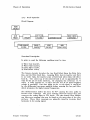
Motor Speed Control
Block Diagram-
I I
CI:MPARAKR
HI
I
SfAR1ER
I
,
H
i
~L
SFNSCB
INIEGRA1rn
I
1
C1.RRENT
CINIRa..
I
~
I
SPINJLE
~DKR
I
Functional D escriptionInitially, when power is first applied, the disk is stationary and the Hall
effect transistor will output a high or low level, depending on the
physical position of the motor. This DC level will keep Ql turned off,
allowing CS to charge up. Pin 1 of Comparator A2 will output a low
level that travels through R12 and forces pin 7 of A2 high. As a result,
Al will be off and maximum current will flow into the coil selected by
the level ot" the Hall effect sensor.
As the motor speeds up, the Hall effect becomes a square wave
responsible for both selecting the motor coil to receive current and
controlling the amount of current applied. Current is supplied alternately
to coils A andB as the Hall device senses the motors physical position.
Depending on the time between high going edges of the Hall effect
sensor, Ql will be turned off long enough for CS to charge to mor ethan
4 volts and force pin 1 of Comparator A2 low. This low pulse will turn
on pin 7 of Al whose resulting 6 volt output pulse will direct pin 7 of
Integrator A2 to allow more current to enter the motor coils.
The sequence of normal operation is as follows:
1) The Hall effect sensor relays speed and position information to the
speed error comparator and to the current controller.
2) The speed error comparator, pin 1 of A2, generates a low spike whose
duration is dependent on the speed error. A slow speed will result in
the low pulse being longer.
Seag ate Technology
PAGE 9
5/1/82
Theory of Oper ations
ST-506 Servic e Manual
3) The speed error information enters the starting circuit which functions
to pass a low frequency signal directly to the integrator indic ating
maximum error during start up. The starting circuit also inverts the
speed error information and combines it with a carrier that properly
biases the integrator.
4) Pin 7 of Integrator A2 translates the error information into a level
appropriate for biasing both halves of Ie AI:; which functions to control
the current sourc e.
5) The current control, IC A3, supplies the proper amount of current for
attaining proper speed as directed by IC AI.
Seagate Technology
PAGE 10
5/1/82
Theory of Operations
2.3.2
ST-506 Servic e Manual
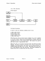
Auto R ecalibration
Block Diagram-
512PlLSE
aINIER
lP 10
SPEID
RECAL
TRACK
DRIVE
PULSE
ZERO
READY
I~ ~AIJ---------------------.;_......J
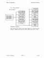
Functional D escriptionUpon initial power application, the up-to-speed counter, up-to-speed latch,
and recalibration latch are all reset. Before the drive can perform any
read, write, or seek operations, it must first become Ready. At
power-on, Ready is a combination of the drive being up-to-speed and an
active Track ~.
As the drive begins to spin, an index pulse from the Index sensor is
supplied to the index counter once each revolution. When the index
counter reaches 512, the drive is assumed to be rotating at its full speed
of 3600 revolutions per minute. The output from the up-to-speed counter
clocks the up-to-speed latch. Since the recalibration latch was reset at
power-on, it will force the direction of the stepper motor outward. If
the heads are not positioned over Track ~, each successive index pulse
will increment the up/down counter. For each increment of the counter,
the phase encoder will select a stepper phase that moves the heads one
half of a track closer to Track~. If the heads are behind Track ~, they
will move to Track ~ immediately, since at power-on the up down counter
will be reset to Phase "A".
When the heads reach Track ~, the recalibration latch will be clocked
high. In its high condition, the recalibration latch will release the
Direction line and block any future index pulses from being gated through
as a step pulse. The recalibration latch, in conjunction with the
up-to-speed latch, will provide the Ready signal to the drive interface.
Approximately 15 milliseconds later, the seek complete timer will cause
the Seek Complete signal to go true.
Seag ate Teclmology
PAGE11
5/1/82
Theory of Operations
ST-506 Service Manual
The active state of Seek Complete is a signal to the controller that
normal operations can begin. The up-to-speed and recalibration latches
will stay set until power is interrupted or drops ·more than 20% below
normal. If this occurs, the recalibration sequen.ce will again be initiated.
Seag ate Technology
PAGE 12
5/1/82
Theory of Oper ations
2.3.3
ST-506 Service Manual
Drive Selection
LINE DRIVER
to interface
Block DiagramLINE REOHVER
fran interface
Ifran
SIEP Pi.LSES
interface
I
I
DRIVE SELECf 1
DRIVE SELECT 2
DRIVE SELECf 3
DRIVE SELECf 4
I
I
1
WRITE GA1E
fran interface
I
DRIVE SELECIID
to interface
r
I
WRITE DATA
fran interface
[
A~IVIlY ~
tnternal
to interface
I
READY
to inter f ace
I
UACK _
I
SEEK <XMPlEIE
to interface
II
I
WR~1E FAU.T
to interface
I
I
IIDEX
to interface
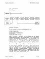
Functlonal 0 esc I1p tlonDrive Select serves only to gate other signals to or from the drive
interface. Without Drive Select, the drive cannot read, write, or seek.
Seagate Technology
PAGE 13
5/1/82
Theory of Operations
2.3.4
ST-506 Service Manual
Step Operation
Block Diagram-
DIRECfICN
INIERFACE
STEP
STEP
. PULSE
SE<nD
STEP
DRIVE
SELECf
Functional D escriptionIn order to step, the following conditions must be true:
1) Write Gate inactive.
2) Write Fault inactive•
.3) Direction In if Track
fJ is true.
4) Drive Ready
5) Step pulse on the interface.
-When a step pulse is applied to the drive interface, the step circuitry
will immediately process it. The pulse is changed to 1.0 microsecond in
width by the monostable multivihrator and is then gated through to the
up/down counter. The counter will count up if the Direction line is low
and will count down if the Direction line is high. An increasing count
will cause the PROM to select motor phases that move the heads toward
Track ~. -The outputs from the PROM are active low which turn off the
pre-ddver transistors. The inactive state of any pre-driver transistor
causes a current flow through the Darlington drivers.
To ensure fast head settling, the stepper motor is always locked between
two phases. For this reason, the stepper circuitry must receive two
steps for each single track increment. Subsequent to receiving an
interf ac e step pulse, an internal step pulse is output by the second step
generator. This second pulse is injected 2.8 milliseconds after the first.
This time interval is the optimum value to take advantage of the motor
momentum and obtain the quickest settling time.
Se ag ate Technology
PAGE 14
5/1/82
Theory of Op er ations
ST-506 Service Manual
Approximately 15 milliseconds after the last internal step pulse, the
retriggerable monostable multivibrator will time out and generate the
Seek Complete signal. Note that during the stepping routine, the
multivwrator is constantly triggered which maintains an inactive signal on
the Seek Complete line.
Se ag ate Technology
PAGE 15
5/1/82
Theory of Operations
ST-506 Service Manual
TABLE 2.1
1RACK
o
SIEP
o
1
2
2C - PIN 3
1
o
2C - PIN 2
1
2C - PIN 6
1
2
3
3
4
6
7
1
o
1
o
1
o
1
o
o
1
1
o
o
1
1
1
1
1
o
o
o
o
1
2D - PIN 1
1
1
1
1
0
0
1
1
2D - PIN 2
0
0
0
1
1
1
1
0
2D - PIN 3
1
1
0
0
1
1
1
1
2D - PIN 4
0
1
1
1
I 0
I
I
I 1
I
I
I 0
I.
I
I 1
I
1
0
0
0
IC 2C
IC 2D
8
= Step pulse encoding.
= Phase sequencing.
Seagate Technology
PAGE 16
5/1/82
Theory of Operations
2.3.5
ST-506 Service Manual
Read Operation
Block Diagram-
Is~crl
:::t:
PASsl
rna;s I
I HEADS H I ·PREPMP II~-"""'il\.avFILlER
.---1IDIFFERENrL~TCR I,"---.1ZERO
D~--CIl:R
+0-----,
Mev1
TThE IXMAIN""---I
FIL1ER
I READ Q\TA I
Functional D escriptionIn order to read, the following conditions must be true:
1) Write Gate inactive.
2) Write Fault inactive.
3) Drive Select active.
4) Head Select active.
The binary decoder decodes the two Head Select lines, the Vlrite Gate
line, and the Write Fault line. Assuming Write Gate is inactive and there
is no write fault, the inactive state of both head select lines will select
head fl. The center tap of the selected head is set to approximately +5
volts by the use of series resist or s. By changing the ref er enc e to +5
volts, 0 volts appears as -5 volts and the use of an actual negative
voltag e is precluded. Raw data riding on the +5 volt signal is amplified
by the differential two-stage amplifier before entering the low pass filter
which attenuates the higher unused frequencies.
The differentiator shifts the data by 90 0 causing the data peaks to
become zero crossings. The zero crossing detector senses this and
converts the analog input to TIL levels. The time domain filter inhibits
any false zero crossings that may be found on the outer edge of the disc
surface. These false crossings are primarily caused by excessive third
harmonics in the analog signal.
Seagate Technology
PAGE 17
5/1/82
ST-506 Service Manual
Theory of Operations
The differential receiver and 2-input Exclusive-OR gate form a
bidirectional monostable multivibrator. The output of this device is
delayed 60n5 by the four Hex Schmitt triggers. This delay is used to
clock the output of the zero cross detector into the D-type flip-flop.
Any false clocks caused by a false zero crossing does not change the
state of the flip-flop.
The last differential receiver and 2-input Exclusive-OR gate form a
bidirectional monostable multivibrator that establishes the width of the
data pulse output from the drive. The line driver converts the data
pulse to differential RS-422 levels. '
Seagate Teclmology
PAGE 18
5/1/82
Theory of Operations
2.3.6
ST-506 Service Manual
Write Operation
Block Diagr am-
1~~"J----------"'"
I~I--~
I
HEAD
ISELECf
PlLSE
R/W
GENERA1"rn
HEADS
I
t------------------I
Functional D escriptionIn order to write, the following conditions must be true:
1) Write Fault inactive.
2) Drive Select active.
3) Drive Ready active.
4} Seek Complete active.
5} Write Gate active.
With write gate active and all the above conditions true, +12V is supplied
to the write cucuit current source which provides a constant 25ma (50
ma peak to peak). When active, Reduced Write Current will pull
approximately lma out of the current source. nus reduces the peak to
peak write current to approximately 46ma.
MFM write data is received by the line receiver and clocks the D-type
flip-flop. The driver transistors alternate write current between the
windings of the selected head. The center tap of the selected head is at
ground potential when Write Gate is active. When Write Gate goes false,
the D-type flip-flop is both reset and preset. Both driver transistors are
biased off and +12V is removed from the write circuit.
Seagate Technology
PAGE 19
5/1/82
Theory of Oper at ions
2.3.7
ST-506 Service Manual
Fault Detection
Block DiagramHEm SELECf
. <IMPt\.RA'! tR
IDN \O..TAGE
IX:
PavER
aMPARA1:tR
-WRllE
'C'AT lI'T
....
............
~
'.
WRIlE
GAlE
I~~~----Functional D escriptionAny 'combination of the following events will cause a Write Fault
condition and will prevent the drive from writing: .
1) Multiple heads selected.
DC voltages more than 20% low.
Write Gate active and no write current.
Write Gate inactive and write current.
Seek Complete inactive.
6) Drive Select inactive.
7) Ready inactive.
2)
3)
4)
5)
The Head Unsaf e circuit monitors the head select output for the
following conditions:
I}
2)
3)
4)
No head selected.
Multiple heads selected.
Head selected for read during write.
'Head selected for write during read.
The above circuit constantly sums the head center tap voltage. If the
voltage exceeds the upper or lower threshold established by the resistor
divider, the circuit provides a Head Unsafe output. The upper and lower
thresholds shift correspondingly when Write Gate is active. A capacitor
delays this change to allow for the change from read to write. If any
unsafe condition is sensed, the Write Fault line is activated and +12V is
removed from the write circuit.
Seagate Technology
PAGE 20
5/1/82
Theory of Operations
ST-506 Servic e Manual
If the DC power degrades by more than 20%, the power unsafe detector
circuit will select a nonexistant head, activate Write Fault, turn off
write current, and initiate a recalibration sequence. Plus 5 volts
dropping below 4 volts will forc e the +5 volt comparator to a high levd.
Plus 12 volts dropping bdow 10 volts will force the +12 volt comparator
to a high level. When either comparator turns on, the Iesulting low level
is gated through to the head select decoder and output to the drive
interface as an active Write Fault signal. A low voltage fault condition
will also turn off the write current source. Additionally, this fault
condition will reset the up-to-speed and recalibration latches, initiating
an auto recalwration sequence.
Write Gate and write current are continuously tested. If one is ever
active when the other is not, a fault condition will occur. This signal is
gated to the drive interface and head select decoder. It will also be
gated to turn off the write current source. In addition to the three
above listed fault conditions, Write Gate is compared with Drive Select,
Seek Complete, and Ready. If an improper condition exists with any of
these signals, write current will be shut off.
Seagate Technology
PAGE 21
5/1/82
ST-506 Service Manual
Theory of Op er ations
2.4
Test Point Description
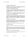
Test Point 1· (Step Pulse);
Test Point 1 may be used to monitor the interface step pulses. Only the
trailing edge of the ,pulse may be considered valid (transition from
negative to positive). If step puises are issued at a 3.0 millisecond rate,
the signal at Test Point 1 should resemble Figure 3.1.
Test Point 2 (Step Timing);
Test Point 2 may be used to monitor the internal step circuitry. For
each step pulse on the interface (Test Point 1), two step pulses must be
seen at Test Point 2. Note that if the Half Step ("H") option is
activated, the second internal pulse will be defeated.
To adjust the internal step circuitry, trigger on Test Point 1 and adjust
R63 for a delay of 2.8 milliseconds (+0.0, ....05) at Test Point 2. Only
the tr ailing edg e of the pulses may be considered valid. .If step pulses
are issued at a 3.0 millisecond rate, the signal at Test Point 2 should
resemble Figure 3.2.
Test Point 3 (Track Zero Sensod;
Test Point 3 may be used to monitor the Track Zero sensor.
level is a valid Track Zero indication.
A low logic
Test Point 4 Ondex Sensod;
Test Point 4 may be used to monitor the Index sensor. A highlogic
level is a valid Index indication. Only the leading edge of the pulse may
be considered valid. The typical signal at Test Point 4 should resemble
Figure 3.3.
Test Point 4 may be used to adjust the spindle motor speed. Monitor
Test Point 4 and adjust R3 on the :Motor Control P.C.B. (accessible
through the side frame) for a period of 16.67 milliseconds, ±1%.
Test Point 5 (Seek Complete Timed:
Test Point 5 may be used to monitor the Seek Complete timer. The
timer should go true approximately 18 milliseconds after the last
interface step pulse is received. To observe the Seek Complete timer,
trigger on Test Point 1 and monitor the delay at Test Point 5. Only the
trailing edge of the pulses may be considered valid. The typical signal
at Test Point 5 should resemble Figure 3.4.
Seagate Teclmology
PAGE 22
5/1/82
Theory of Operations
ST-506 Service Manual
Test Point 6 (Track Zero/Phase "An);
Test Point 6 may be used to check the operation of the Track
ZerolPhase "A" circuitry. A high logic level indicates the drive is at
Track Zero with the stepper motor phase "A" active.
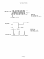
Test Points 7 and 8 (Differential Read Filted:
Test Points 7 and 8 may be used to observe the differential read data.
The typical amplitude of the signal resulting from adding the two
channels is 250 millivolts. It is ·important that Test Points 9 and iO ale
used as ground.
Components of 1.25, 1.66, and 2.5 MHz should be observed. A full track
record of high frequency data (UiL or l.ll.J.) should resemble figure 3.5.
Test Points 11 and 13 (Time DQtnain Filter):
Test Points 11 and 13 may be used to observe the operation of the Time
Domain Filter. Trigger on Test Point 11 and monitor the delay at Test
Point 13. Typically, the delay observed should be 50 to 60 nanoseconds.
A
full track record of high frequency data (UiL or l.ll.J.) should resemble
1:"': __ • __ .,
~
~·~lSUJ.~
,",.V.
Test Point 15 (Force Seek Outward>:
Test Point 15 may be used to force the drive outward past Track ~.
Grounding this test point defeats the Clash stop prevention circuitry and
allows the additional stepper motor travel. This is a convenience feature
for use in the drive manufacturing process.
Note: Improper use of this function may permanendy damage the drive.
Test Point 16 (Half Step);
Note: This test point applies to Main Control P.C.B. PIN 20040 and
greater.
Test Point 16 may be used to temporarily activate the Half Step (UHf!)
option. Grounding this test point performs the same function as
activating the Half Step option at I.C. position 6B (6C on p.e.B.P/N
.20019). This is a convenience feature for use in the drive manufacturing
process.
Test Points 9, 10, 12, and 14 (Convenience Ground);
For any of the above functions, use the ground test point that is
closest proximity to the active test point.
Se ag ate Technology
PAGE 23
10
5/1/82
TEST POINT TIMING
--u.
TEST POINT 1
L
FIGURE 3.1
TEST POINT 1
STEP PULSE
3.0ms
LJ
TESTPOINT1
U
L
J
3.0ms
LJ
TEST POINT2
Lru
.I
~
2.8ms
3.0ms
L.
, n----r.S f-
200us typo .
16.67ms
± 1 0/ 0
TEST POINT 1 .
.1
--1
FIGURE 3.3
TEST POINT 4
INDEX SENSOR
--, I~-----------t~S-
U
~I
TEST POINTS
5f-'
FiGURE 3.2
TEST POINT 2
STEP TIMING
-==!J
Jl~--
TESTPOINT4
Sr-
FIGURE 3.4
TEST POINT 5
SEEK COMPLETE TIMER
500ns typo
I
L 1 s m s typo
1--~S5-
-J
PAGE 24
TEST POINT TIMING
MmWWf~mvtyp"
,1--1·
TEST POINTS 7 & 8
I I I , rI I I I I I I I I I I f I
JL
I
TEST POINT 11
~
~
-r
FiGURE 3.5
TEST POINTS 7 & 8
DIFFERENTIAL READ FILTER
200n5
) j-
I
I
"L
200n5
50-60ns
FIGURE 3..6
TEST POINTS 11 & 13
TIME DOMAIN FILTER
TEST POINT 13
PAGE 25
TEST POINT LAYOUT -
p.e.B. PIN 20019
(
I
-9
0"7
I
ll...----
_-4n
-IV·
_
PAGE 26
TEST POINT LAYOUT -
p.e.B. PIN 20040
.~
I
-9
-8
-7
-1
-3
-4
-10
.1~
IV
-11
-6
-14
-2
-15
l
-5
PAGE 27
12 •
13 -
II
I
ST-506 Service Manual
Theory of Operations
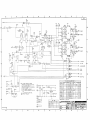
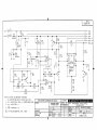
2.5
51'-506 Schematics
Main Control P.C.B. PIN 20019
Main Control P.C.B. PIN 20040
Motor Control P .C.B. PIN 20003
Seagate Technology
PAGE 28
5/1/82
8
I
7
6
5
..
_-
4
_._-----_._-'--- .
3
---
2
II
-_+-STEP
~---==_.DIRECTION
o
1<2/
.!30
-.L.W -0 SEJ.£c.r
c
--·-----_-WKFIJI.t.T
c:
o
>
;)
n
,J
o
+""PIT. CIlTA
-WRITE DATil
EI
B
--_·_-====--+-t-·-
- - - - - - - . . tOUT ElVA.
,. PC.4DY
't~V
:~~tJ
L.w-'~TY
-----!...W"- -AE:;;"TY
A
zoo~
8
... CI£tEC.TION . _ _ - . - - _ _ _ _ _ _ _ _ _ _ _ _ _
1(~"~>="'-10
1
~
-
2
5
6
7
8
----------,
+120"
I1.ilZ
"l.ik'-
o
.. "v
"2."
e~
"li~
o
--~6
~r~----
.s"
~ 1277
<-
'Ok'-
':~J'7
"1D
.:L_~-:...r--.....
~-,.--....~
c
TP'5
c
l_
I!J,",*- - -CA:k'- ¢SJiil
----_._-------+._--+--+
-'50:. (CMP
-----.---------4f--....,......-+--+j@~
~
~)f!
22"
-
5l<EIC.
COMPLETE
- I£A"'"
... 12EADY
B
. ~':,~~f ..--_ .. - - - - - - - - - - f - - - - 1 f - - - - - - - - - - - - - - - - - - - - - - - - - - - - - - - - - - - - - - - - - .
NOTES: ""'LE""" O'THEl;!W,,,,e
A(..~ ["I. 2.clQl~"fOe~
Z.G.~I?TANc.E:.
. . .At..uE~ AEE IN ~MS /~W..S"/", .
,AeJ: /e'IV
'
VALViO", A12E IN M'CI20~ArzA~
,
CAPACITANCE
..
.')IOO(:OS
-'j(-
ACE:
.~
~e
It IE
-
B
INDE,X
-wen£:
FAUl..T
"pECJ~IEO
I.
2
5.
=-~)'"
IN"·11·:16
IND'CA'~'!>
" -V7
~ INDICATE'-!.
CONN"CToe .:11
•
INOICA1"'" CONNECTOI2 J'l TH.I2U .16.
[!]
PAf:T
NOT
TEST PolNT PIN",.
IN 6TAL.i.. EO.
A
A
MU(l~"TOIHQINlI'UHO ,"c.•no-.., :~QIC~IOIT~-~lI.IIlIllIl.IIIII1I11••••
TOUJU.HCf UNUM
C_12':l..,..0-t-"''-L....-f-_ _
Sil7
8
7
6
~~
5
L<o
DATI
NO.
mu
It:.=:.Pw6"A..,.t.-:6Y·COl'rnw,;;".,E.---,.:.o==::;.:;,,'---;~~~~4:~:+~-D~~+;;~~::j1 .....:§~:·~-~'~...;1:::!:=1
O","1IWI11 MOTtO
)( II>
r-----4------,r-----'-'--;-
UNIM : : . _ _
I
2>'J 61
10
~
.02'16-
=- __.=:::&2_-J._-J.-=--',_~
..
__
'lOC_."_q_-_OO_'- - - - '
3
4
5
6
7
8
2
... 1'2'v'A
r
-
125
I!I.
{.2~
1lJ(
III
1.2K
o
ee
1.2K
J'S
<l
~n;p
I
-DIl2,,'-"nON *~~--4>---+-"'<IJl'2:'L---'
-1-IEJt..O ~1...1.. *~-
-!-If-AD
'12vA
... ,LVA
+1'2.\1
__-&--::n
~'- 2' *~
31-+"""-,,-,"+~
P'-1'y'\.1\--1>--H~+--+--l,.,
eo
'5
~'VV'Ir ..----l --1~""'-+---110
.2
q
P'-JV\1\r1~+--+---Hr-+--I1<l
29
1<10
I'll
1ZJ2
IO~
lOr.
lOt.
10K.
II
'"
I'!
,-.;
----------------++--_-w,t
c
FA.......T
c:
I~
41
'--
B
--l
ell
J:..~6
-=
B
10%
- - - - - - - - - - - - - - - - - - - - - - - - - - - - - - - = - _ . . . = . . . : ._ _. -------------------~t__--------------
+-/------l-------'
' - - - - - - - - -..--------+-------/--------------.....--
-+
OOT ENA
.------+---------J.------------,.
A
A
8
7
6
5
r--'
4
L_~_~--;:;;;-;:;-
_2
I
l.C04O- ':''01
+12~
o
o
c
c
t2c.'l
411'
[
____ -_II12~T
as
lEI
czz
10)(
_L4.7.10~
-=-
1l1O.4'1t:,
- TI2Al.t:.
--------------/-----f--;_
m
- '!>l' COMI'
81(
---------------I-------f--t-_-':~~re-------=--I(
o
%1 u
..............-
----------+-----t~---1r-~)2'---_--
'foEEI<- CCNIPUiiT&
-~r:tt
... CZEADY
B
:~'"
0
-----------------.-1--..
-W12rre.
FAULT
-
~
B
INOli.lC
'~'>
---l~----~ -WI2ITIO
"ALLor
8.
"3
NOT"Sb: l.JN<.£_ orHe.l2WI.,;e "'!>PEC.IFIEO.
I.
\2E.,,";TAN<:li vN.U6"!> Aee IN OHM~, '1~ W, ~%.
2.
ALL I'Y. 12E~~T012S AIZ6 'Ie w.
,. CAPJoi:.I"AIJC.E V~ Ae£ 11.1 1o\1l1ZD~ +60-20"
4.
DiODES "'laG
1N4I.. e
'5.
INCI'-A,.e'!> CONNE.C"oe. ':11
reo
[~l
---M-
-V-
~
PA<'T
INOluo.T£~ CONNE(.Toe. J"2. THlZU 38,
INDICATES
NOT
TE~
...
POINT PI,..S.
IN~TALLIiC
T
~ c:.1~· ro..YU>12~.... ATE:.'50V.1:IO·/o
PON"> I-~~
'2.4,",6,12,
1M':::'
~.lfQ.lq.20
8
7
6
]
5
HAIOrCU
""0:.
C<»I~INQIHUItIHO,:~l.IHlfll
I=.,...~=...
~:
20040-001
1'1
2
>( 000
OIHE
'lOTtO
'-_----i-t........
--.-~-::
;-.-
_.
O:~
'3:34
r
3
6
"7
SEAGATE TEe
TIT1.I
PNB
:i"":t·e~BZ@joz~~lllT~""'_~AL~"~/'oJLlTIm:3~!~~~!I:::t
~&
~
=:r .....,.
0Clfl1Ol
4
0"~4?
.'
,...
12.
!.
4
.!i-
2
A
_---------------------L---
'."IT NO.
'20003·001
+ /2. V5\2
f:/
I
E2.
C,N D
,
~--..........--~.__-.---'---.----------.-----
.c:~
-~
CQI
~~f----HlI~I---+---e--4t------'
3 )(
+12V
C~ND
+<OV
-------~ COIL A
INLlCD5
COIL B
r--------~
1
ee
t21
;30
~-4II--.......-----_t-----fV\/v--+----~
....~ ~
HALL IN
I~
- CIO
Il}.w.1.%
- .001
.Jeo
, en
8
4./~
9
A3
II
::3
~
~
14
ULN
-}
4
10
201~B
C.,2 -=t.
15
'5 ,2.
.II
I
-.-
---r-l12ISI
.2
'7
12.11
IO~
IN'1I.::l6
2.W
2013
'219
lOOt::
.2-
J2./2.
2.W
SlOt:.
NOTE'S: UNLESS OTHE2oW/'5E. SPEC,.IFIED
I.
ALL e.E'SIST0C25 A12E. IN OHM'S) ~W)5%
2. ALL CAPAc-noes AeE
3.
-r-
INDICATt:=.'6
.j
IN
M ICeOl=-Ae,AD<G 110%1
@J
TOLERANCE UNLESS
DTHERWISE NOTED
I
-------t
-4.~ INDIC.AT~'S ,j2.
C5 - POL'fCA12BONATE
- - -__
II
50V
J
"!: lOX
EC HISTORY
MUST CONFORM TO ENGINEERING SPEC. 30130-001
MATERIAL:
L1NEJ\R
DATE
~ SEA
TITLE
ATE TECHNOL
pwB A5S'Y - MTt2. CNTI2L
;;--9'3:2. C2.ZO
':£.I-4EMATIc..
0'23S DETAIL ..jl-.,)
'1·20·61
RELEASED FOR ASSEMBLY
~~-----+~~~:::::::.::::'..::::+O:=E~S.::.:,G:::.N~;;,;,,::::.-+-~..=::::...::.:.I-~:.:,;;;;,.;,:,;;,;~:;.;.;...;.;.;;,;.;;;....,;;;.;;;.;.--1
~.XX
~+::c:
±.XXX
HARDNESS
SURFACE
TREATMENT
NO.
APPRO
ES
MAX
INSIDE
MAX
B
SHEET
SCALE
(0
PART NO
2.0003-001
OF
(0
ST-506 Service Manual
Maintenance/R epair
3.0
MAINTENANCE/REPAIR
3.1
Introduction
The Seag ate Technology ST-506 Microwinchester disc drive does not
require preventive maintenance. Additionally, all units shipped are
covered by a one year factory warranty.. If field m~1ntenance or repair
is required, certain restrictions -apply. Primarily, the environmentally
sealed Head/Disc Assembly (HDA) must not be opened. Seagate
Technology considers a drive to be out of warranty if the HDA has been
tampered with. Any special tools or additional restictions wili be
covered under the appropriate sections.
This sec tion of the ST-5 0 6 Servic e Manual will attempt to cover
adjustments and repair of the field serviceable portion of the disc drive.
Any questions that are not covered in this document should be referred
to the Technical Support department at Seagate Tech.'101ogy.
Seagate Technology
PAGE 34
5/1/82
Main t enanc e/R ep air
3.2
ST-506 Servic e Manual
R emovals/Adjustments
Note: Removal of any assembly not coveted in this section is not possible
without special clean room facilities and tools•
. 3.2.1
Main Control P.C,B,
Tools Required:. 5/64" Hex Driver
Loctite #242
1)
2)
3)
4)
Remove (4) 6-32 x 1/4" Main Conttol P.C.B. mounting srews.
Disconnect PI through P 8, noting their positions.
Slide the Main Control P.C.B. toward the rear of the drive and
remove.
To reinstall, reverse the above procedure using Loctite on the
first three threads of all 6-32 screws.
Note: Avoid flexing the Printed Circuit Cable when removing P 5.
'2
.,.,
-..K _+ __ r __ +-_1 n r
".• e' ".. yLU+
yy ...... '=.. v ...
.I
'D
_\g_H.
Tools Required: 5/64" Hex Driver
Loctite #242
1)
2)
3)
4)
5)
6)
7)
Remove (4) 6-32 x 1/4" Main Control P.C.B. mounting screws.
Disconnect PI through P 8, noting their positions.
Slide the Main Control P.C.B. toward the rear of the drive and
remove.
Disconnect Motor Control P.C.B. PI and P2, noting their
orientation.
Remove (2) 6-32 x 1/4" Motor Control P .C.B. mounting srews.
Remove the Motor Control P.C.B.
To reinstall, reverse the above procedure using Loctite on the
first three threads of all 6-32 screws.
Note: Whenever the Motor Control P.C.B. is replaced, or if any of its
components are changed, the spindle speed must be adjusted.
Connect a frequency counter to Test Point 4 Ondex) and adjust R3 on
the Motor Control P.C.B. (accessible through the sideframe) for a period
of 16.67 milliseconds. The frequency counter must average 100 samples
per minute minimum. Additonally, if C5 is replaced, the Motor Control
P.C.B. must be burned in for at least 12 hours to setde the capacitor
before adjusting the speed.
Seagate Technology
PAGE 35
5/1/82
ST-506 Service Manual
Maintenance/R epair
3.2.3
Spindle Brake
Tools Required: 5/64" Hex Driver
Loctite #242
10 Mil Shim (.010'') (Flexible)
1)
2)
3)
Remove (4) 6-32 x 1/4" Main Control P.C.B. mounting srews.
Disconnect PI through P 8, noting their positions.
Slide the Main Control P.C.B. toward the rear of the drive and
remove.
4) Disconnect P 2 at the Motor Control P .C.B, and free the brake
wires from the retaining clip.
5) Remove (1) 6-32 x In brake mounting screw, washer, and spacer.
6) R emov e the br ak e sol enoid.
7) To reinstall, apply Loctite to the first 3 threads of the brake
mounting screw. Replace the brake solenoid, spacer, washer,
and mounting screw but do not tighten.
8) Insert the flexible 10 mil shim between the brake pad and the
spindle motor housing.
9) Move the brake toward the spindle motor housing until the
solenoid spring assembly is compressed and a slight resistance
is felt on the shim.
10) Tighten the 6-32 brake mounting screw and verify that the
contour of the hI ake pad aligns with the spindle motor housing.
11) Route the brake solenoid wires through the retaining clip and
connec t P2 to the Motor Con tlol P .C.B.
12) Reverse steps 1 through 3 to replace the Main Control P.C.B.
using Loctite on the first 3 threads of all 6-32 screws.
3.2.4
Index Sensor
Tools Required: 5/64" Hex Driver
Loctite #242
30 Mil Shim (.030'')
1)
2)
3)
4)
5)
6)
7)
8)
9)
Remove (4) 6-32 x 1/4" Main Control p.e.B. mounting Slews.
Disconnect PI through P 8, noting their positions.
Slide the Main Control P .C.B. toward the rear of the drive and
remove.
. Remove the connector from the front panel LED, noting the
orientation of the connector.
Free the index sensor wit es from the retaining clip.
Remove (2) 6-32 x 1/8" index sensor mounting screws and
mounting clamp.
Remove the index sensor.
To reinstall, apply Loctite to the first three threads of the
index sensor mounting screws. Replace the index sensor,
mounting clamp, and mounting screws but do ·not tighten.
Rotate the spindle motor housing until the silver index tab
aligns with the index sensor.
Se ag ate Technology
PAGE 36·
5/1/82
Maintenanc e/R ep air
ST-506 Servic e Manual
10) Using the 30 mil shim, adjust the gap between the index sensor
and the index tab.
,
11) Tighten the 2 mounting clamp screws and verify that the gap
is 30 mils.
12) Route the index sensor wires through the retaining clip and
reconnect the LED.
13) R evelse steps 1 th!ough3 'to' replace 1"h e Main Control P .e.B.
using loctite on the first three threads of all 6-32 screws.
3.2.5
Ground Spring
Tools Required: 5/64" Hex Drivet
Loctite#242
1) Remove (4) 6-32 x 1/4" 1vIain Control P .C.B~ mounting srews.
2) , Disconnec t' PI through P 8, noting theit positions.
'3) Slide the Main Control P .C.B. toward the rear of the drive and
remove,
4) Remove (1) 6-32 'x 'l/S" g~oull(f spring iIlounting'screw and spacer.
5) Remove the ground spring.
.
6) To reinstall, apply Loctite to the first 3 threads of the
_...:.
..:1
......
_
''P'I''
gl:UUllU :»pung wouDung 5CI:eW e
.Kep.1aceme grouno spI1ng,
spacer, and mounting screw.
-: ,,'
.
7)' Center the ground spring over the spindle motor contact ball
and tighten.
'
S) Verify that the ground spring b':ltton and spindle motor ball are
clean and making good contact.
9) Reverse steps 1 through 3 to replace the Main Control P.C.B.
using Loctite on the first 3 threads of all 6-32 screws.
~.
3.2.6
Track
_11
. . .
e Sensor
Tools Required: 5/64" Hex Driver
.050" Hex Driver
Loctite #242
1) Remove (4) 6-32 x 1/4" Main Contr'ol P .C.B. mounting srews.
2) Disconnect PI through P S, noting their positions.
3} , Slide the Main Control P.C.B. toward the rear of the drive and
remove.
4) Remove (2) 6-32 x 1/8" front panel mounting screws.
5) R emov e the front panel. It is not nec essary to t emov e the LED
connector.
6) Remove (2) 2-56 x l/S" track ~ sensor mounting bracket
retaining screws.
7) Remove the mounting bracket and track ~ sensor, noting the
orientation of the track ~ sensor.
S) To reinstall, reverse the above procedure using Locthe on the
first 3 threads of all screws.
Seagate Technology
PAGE 37
5/1/82
ST-506 Service Manual
Maintenance/R epair
Note: Proper POS1tloning of the Track ~ sensor is important. It
is recommended that this adjustment be performed at the factory.
3,2.7
Front Coyer
Tools Required: 5/64" Hex Driver
Loctite #242 1)
2)
3)
4)
5)
6)
7)
8)
Remove (4) 6-32 x 1/4" Main Control P .C.B. mounting srews.
Disconnect Pi through P 8, noting their positions.
Slid e the Main Control P .C.B. toward the rear of the drive and
remove.
Remove the connector from the front panel LED, noting the
orientation of the connector.
Remove (2) 6-32 x 1/8" front panel mounting screws.
Remove the LED and grommet from the front panel, noting the
orientation of the LED.
Remove the front panel.
To reinstall, reverse the above procedure using Loctite on
the first three threads of all 6-32 screws.
Note; A water base hot welt glue way be used to secure the
LED/grommet assembly.
3.2.8
Front Coyer LED
Tools Required: 5/64" Hex Driver
Loctite #242
1)
2)
3)
4)
5)
6)
Remove (4) 6-32 x 1/4" Main Control P .C.B. mounting srews.
Disconnect PI through P 8, noting their positions.
Slide the Main Control P .C.B. toward the rear of the drive and
remove.
Remove the connector from the front panel LED, noting the
orientation of the connector (Black wire to single dot).
Remove the LED and grommet from the front panel, noting the
orientation of the LED.
To reinstall, reverse the above procedure using Loctite on the
first three threads of all 6-32 screws.
Note: A water base hot melt glue may be used to secure the
LED/grommet assembly.
Seagate Teclmology
PAGE 38
5/1/82
Main t manc e/R ep air
3.2.9
ST-506 Service Manual
Side Frames
Tools Required: 5/64" Hex Drive.r
Loctite #242
1)
2)
3)
4)
5)
6)
7)
Remove (4) 6-32 x 1/4" Main Conttol P.C.B. mounting s.rews.
Disconnect PI through P 8, no_ting their positions•.
Slide the Main Conuol P.C.B. toward the .reat of the drive and
.remove.
Remove (2) 6-32 'x 1/8" front cover moun-ting' sc.rews. It· is not
necessary to remove the LED connector.
Remove (4) 6-32 x 5/16" side frame mounting screws, washers~
grommets and spacers.
Remove the right and left side frames.
To reinstall, reverse the above procedure using Loctite on the
first three th.reads of all 6-32 screws.
Seagate Technology
PAGE 39
5/1/82
illustrated P arts Catalog
4.0
ST-S06 Servic e Manual
ll.LUSTRATED PARTS CATALOG
4.1
Physical Locations
4.1.1
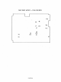
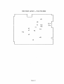
4.1.2
Drive Exploded View
Connectors Exploded View
Seagate Technology
PAGE 40
5/1/82
4
_--L
iI
~
B
I
I
I
1,//"
v"1V~
A
2
3
4
o
-
1
o
BRUSI-ILcSS D.C. /VIOTOR
CABLE
CABLE
STEPPER MOTOR CABLE(PB)
TO CONNECTOR .1"8/ CONTROL P.C.B.
OPTICAL /NT€RRUPTEF.1 CA8L£(P7)
TO CONNECTOR J7, CONT~'OL RCB
"- '\
\
\
c
\
c
I
-
~
MTR. CNT POWER CABLE (P4)
TO CONNE.CTOR J4, CONTROL RC.B.
/
INDEX SENSOR.
CA8LE(P~)
TO CONNECTORJG:>,CONTROL PC.B.
/
..... , /
PRINT£D CIRCUIT CABLE (P5)
TO CONNE.CTOR J5,CONTROL PCB.
B
B
.sPINDLE BRAKE CA8LE
MUS,. CONFORM TO ENGINEERING SPEC.
A
MATERIAL
EC HISTORY
TOLERANCE UNLESS
OTHERWISE NOTED
I----....-----~LINEAR
:t:t'.XXXXX
DATE
1-7-81
NO.
~.
SEAGATE TECHNOL
A
O£TAIL
RELEASEO FOR ASSEM8lY
E.A.~.
f---J---ll-----
I=HA::'::RD":N::::ES-~Sl-=--=--_-=--=--=--_-=--=--_-=-t-A~N-~G-UlA;;/R~:t~~~-=--=--=--=--_~~-_t:~~-_-=-t-=--_-_-_t"2A1"PRO:":";':':+=:-r-t.-::,,=~SHE;.;;.;ET;.;....=-:::-..;(;.;.)f
CASE DEP'fH
SURFACE
I-:E:::S
TREATMEtlT
4
3
CIESIGN
----I ~~":IIS
IM.IN
2
OUTSIDE
INSIDE
MAX
IMX
A
TITLf
C
~~
~NIT
1
M).
-1
illustrated P arts Catalog
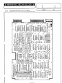
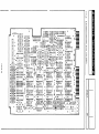
4.2
ST-506 Service Manual
Component Locations
4.2.1
4.2.2
4..2..3
Main Control P .C.B. PIN 20019
Main Control P .C.B. PIN 20040
Motor Control P ,.C..B,. PIN 20003
Seagate Teclmology
PAGE 43
5/1/82
r1TLE:
SHEET
4.2.1 MAIN CONTROL P.C.B. PiN 20019
IIiii"tlill IIIIIIU ~~~~~r
rUJIIi 11111
o
00
o
ti\.,J00
O~-
:0~01
: ~ &: ~ : ~ : ~~O: ~ ~ :
0
0
0
0
0
O.
.0
0
•
0\90
o
0
l~
0
lJ}
:
0-.90
0
•
0
.
0
O~
:
0
Q :
0,.90
0
•
0
000
O~
~g}I~ : ~ : ~ ~ :O~O
«J :
0
0
0
0
v ~w~ ~ ~ ~~;
o
0
~
v
0
0
•
ttl
0
n. .
!'
c-J
~
\J
0
e.:~.:~.:;0.
T·
°n°
00
0
I
0
:.0
0,
0
0
.~ 00 • 0,. ~ ~ 0
lil"...9~ o 0
rn .---•. Oi iii ~ ~ v r-II
o
r---'II'
'"
~
hOO
00
00
~
OF
0
0
~~I \J~I-I- -~5t;i :,'
OlL
O .oo.~
T I
G
"> 0
I:
0
0
~9
0
'" l!\
A
0
0
0
_
0
0
0
0
l[l
0
0
W~l~'~~ij
........ 0
0
0
0
0
•
~~
0
0
0
0
0
~
~ r;;-.
~
00
:
••
:
o~cn 0
0 -ll
0 Ci'Cl
0
•
0
0
0
0
~
•
0
O.
0 00
0
I I
•
~
o
.:
r
ITO
0 0
I
Uo!tOl 1 1••..1
~:QI~~~~
~ . . • • ow.
~·.·~"'~o·: WNG~ :OO:QS~~": : :~ : :.: :.: :
I/)
~
.0000
0A---r-"
~o
\J \J \J V
Ol r:-J
0
I
aJ"'~
0
....
,,~'"
...-...
N
0
0
l0
0
0
0
0
0
0
..
0
0t
0"
i!l III
~(i;\
\!J \!J
.0
0
0
0
0
0
0
~ 0
0
0 0
0
0
0
0
0
(j
C!J
0
0
0
0
0
0
o
:..
::r;';':
.~
~\..,i\"J"~
~&~§aQ :)~~h ~ ..: I~.:~:.
• H •
w ·~
Y •
H~;;::~ ~:~ ~[J~ ~;~~.~.~[J~~: -r~~1· ~[J~~:;~[J~
o 0
00
\J \J
'J
0
0
o•
.~ • • O
~
0
0
o.
0
r:i
0
0
• • • • 00
0
0
~
-.9
0
0
O.
•
01
0
0
0 ~ 0
0l..f"L.
~
0
00
0
0
~
0 O!o~ 0
0
0
•
0
~
0
0
•
0
0000
-+
0DO ~ ~~i;~ ~~:L ~·~4 ~~:
0
oo 0
000
000
o 0
0
o 0 ~ 0
o 0
•
o ~ 0
0 ~ 0
0 ('I 00 0 ~ 0 V
0.0.0.0.
til
0
@
o
o
0
V
o@
III
o:~:om.:~:.~.Ione. -0:
o
•
00 •
0
:w
0.'
•
0
ISI~I : : Q.:Q :• ~
l
..4-1..rL-"'-:-' :
:
• Q .~. ~
•
• 000
•
o
DJ\~C
AA
0
•
0
01
•
0
0
I
E~
-l
=i
r
fl:l
~
~
!',J
..
.-
.~
.~.~
.~
125
•
1<1
-~
f1J~
lJ.
~J7
11l. ~
~3
Q4· •
J5
es
•
,• • e ••
~;
....@-z.
C)
m
~
.~~
I
~'oe
C~8
.,J::l.
CJl
7
~
~~
~
.~1:"""1
•••••••
o
~::.O"I (j)
••
• •••••• @.,
.:>
I••••••• • leR4 .-~
-~
••••••• • ••••••••
>ID
I @ 14 '2 D
I
•••••••
•
•••••••
• • • • • • • • ep3 ~
•
• • • • • • • • f2.P'2.
•••••••
~1C:
~
4
••••••
I 2 ?y:
I: ??L
I •
•
•••••• ••••••••• • •••••••
.~.
.~.
•
••••••••
••••••••• ••••••••
,1~
I ~
I·
,• • • • • • • • I2Pl
I
AAAAAAA
••••••••
~.
RClI-
RClO
•
1280:.~._
c.'2.~
..
Z
!',J
I~
o
o
.,J::l.
o
• •
a¥m:
·IE ]
~~
• ••••••• @ •••••••
'iJ
............
•••
E~
• ••••••
i:~""1
.
o
OJ
1'2.
.~~
I
.~
r
:-0
•••••••• @
E_~
•••••••• •
.--@::£}-e
••••••• ••
• ••
·E~
•••••••• •• ••
---e~
R71..
:0
o
@
CA·7
f-o
';2.71
Z
--I
tlj .
••••••••
B
••• 0 ••••
'iJ
o
••
~~
2.21
12.10
Clct
•
~
ell
lJJ8 -1
z
()
C~}: ! • ~ "]
•••••••
~
cl2li
li!.4
12.'1
iF
•
CI2I~
•••• 0 •••
l>
..
O E:==J •••••••
••••••••
• • • • 00 • •
e'2.
1<.1
~
s:
l>
•
•
•
en
~~
.
I
• ~:~R-:~
••
~~~.
•
••
121~
U..t!
m
m
--I
•
I
_n..
I
II
~ ~~~:::J~';2,f-::
C'27
}.~.Jl..
: •
---r
..
I
L
J4
••
•
•
I,
II
-li
o
"
TITLE:
4.2.3 MOTOR CONTROL P.C.B. PIN 20003
I[~-::::::::::::=S=H=E=E=T===::::::::==O=F======
000.
G
~
o--@]-o
0000
~o
0000000.
~
:
:
•
PAGE 46
I
A~<
OOO~OO::O.
JI
1
~
12'2.0
C.9
000000.
I
A\<
0000000
~
~
nlustrated P arts Catalog
4.3
ST-506 Service Manual
P arts Lists
4.3.1
4.3.2
4.3.3
4..2..4
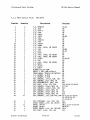
Main Control P.C.B. P/N 20019
Main Control P .C.B. PIN 20040
Motor Control P .C.B. P/N 20003
Spare P arts List
Se ag ate Technology
PAGE 47
5/1/82
Illustrated Parts Catalog
ST-S06 Service Manual
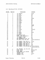
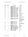
4.3.1 Main COntrol P.C.B.
Item No.
P!JN 20019
Descr ipt ion
C,Yantity
Location
2
1
I.e.
TPQ3904
2E,2G
T r
..4n?n
I"' ..... ""
2B
3
1
4
5
6
7
1
2
I.C. 6330-1
I.C. 7408
I.C. 74123
I.e. 74574
1
loCo 7406
3D
I •C.
I.C.
I.C.
I.C.
I.C.
I.C.
I.C.
I.C.
I.C.
I.C.
4D
2D
1
2
8
9
1
10
1
1
1
11
1
12
13
14
15
16
17
1
2
2
1
1
1
3
1
1
18
19
20
21
22
23
24
25
26
27
28
29
30
31
32
33
34
35
36
37
38
39
40
41
42
Z
1
1
1
1
1
1··
1
7
.. _"-"_
10
3C
2A
3A,6H
74LS221
7445
26L532
74586
7410
7438
2074
74191
7400
7402
6F
6D
2C
5C,5D
2F,lH
lC
4C
4B
I.C. 74LS14
I.C. 7407
I.C. 7404
I.C. NE592
I.C. 26L531
I.C. IM339
R/PACK 220/330 ~1
s-IlNf, 7 PCS, AMP-435704-7
I.C. SOCKET, 16 PIN
I.C. SOCKET, 14 PIN
CAP, ELECIRQYrIC, 22uf, 16V
~, TANT, 4.7u£, 35V, 10%
2
~,
1
1
1
1
CAP, CERAMIC, .03 3uf, X7R, 10%
28
1
25
4
1
2
3
1
Seagate Technology
CERAMIC,
150pf, NPO, 5%
IB, 5B, 6E
SH
3B
3F,5F
6G
4A
6B
6C
6C
6B
C27
CI4,15,22,25,28,29,
42
C17, 24
Cll
C8
CI0
C20
~. CERAMIC, 470pf, NPO, 5%
CAP, CERAMIC, .luf, Z5U,+80,-20% CI-6,11-13,16,18,
19,26,30-41,43,44,
45
Cl3
~, PQYCARB, .lu£, 50V, 10%
DICDE, 1N4148
ffil-17,23-30
CR19-22
DICDE, 1N4003
DICDE, ZENER, 4.3V, 1N5229B
CR18
INX.OtR, 2. 2uh
L1,2
IN:XX.TCR, 10ub
L3,4,6
INX.OtR, 3. 3uh
L5
~,
CERAMIC,
100pf, NPO, 5%
CAP, CERAMIC, 330pf, NPO, 5%
PAGE 48
5/1/82
Illustrated Parts Catalog
I tem No.
Qlant i ty
43
44
45
3
4
1
46
2
47
48
49
50
51
52
53
54
55
56
2
2
1
2
4
1
2
1
4
1
C:::~
JI
3
58
59
60
61
2
4
1
8
62
5
63
64
2
26
65
66
67
68
69
3
1
1
8
9
70
71
72
73
74
75
76
77
78
79
80
1
3
1
4
3
1
3
1
1
15
1
Seagate Technology
ST-506 Service Manual
Descr ipt ion
Location
1RANSISI(R, 2N3468
1RANSISTCR, 2N3904
RESISTCR, l/lNI, 1%, 90.9 GM
RESISTCR, 1/ gN, 1%, 100 OM
R.ESISH~j l/tNli 1%_ 162 aiM
RES I STCR, l/gN, 1%, 178 Cl-M
RESISItR, l/tNl, 1%, 221 aM
RESISI(R, 1/8N, 1%, 909 aM
RESIS1t:R, 1/8fl, 1%, lK
RESISTCR, 1/ g.N, 1%, 4.64K
RESISIrn, 1/gy.{, 1%, 7.68K
RESISTCR, l/oW, 5%, 9.1K
RESISTCR, 1/4W, 5%, 22 aM
RES I SI(R, 1/4W, 5%, 47 (}M
RESIS1:CR, 1/ '-Wi, 5%, 100 ca!
RESIs:rcR, 1/4W, 5%, 150 aM
RESIS1t:R, 1/.wl, 5%, 220 <Hi
RESISTCR, 1/4W, 5%, 270 Cl-M
RESISICR, 1/4W, 5%, 330 aM
Q1,2,3
Q4,5,6,7
R44
R40,41
R19,10
R22,23
R42
R36,37
R48,50,55
R35
R49,51
R80
R98,99,100,101
R33,54
R13,25,34
R67,71
Rl,2,3,4
R14
R5,6,7,8,21,24,29,
38
RES I S'It:R , Ijw, 5%, 470 CHvi
R15,2i,28,4S;46
RESISTCR, 1/4W, 5%, 620 Q-M
R39,53
RESISItR, 1/'fiN, 5%, 1K
RI8,31,32,52,58,
59,62,64-66,75,78,
79,81,89,90-97,
102-104
RESISIrn, 1/4W, 5%, 1.5K
RI6,17,26
R30
RESISfCR, 1/4W, 5%, 2K
RESISTCR, 1/4W, 5%, 2.7K
R76
RESISTCR, 1/4W, 5%, 4.7K
R43,69,82,84-88
RESISItR, 1/<Wl, 5%, 10K
R9-12,47,60,61,71,
77
RESISIrn, 1/4W, 5%, 15K
R70
RESISTCR, 1/4W, 5%, lOOK
R68,73,83
R74
RESISTCR, 1/4W, 5%, 47K
R105-108
RESISIt:R, 1/4W, 5%, 10 Q-M
INSUA1CR 105 1l-iEmv1AllOl-4 005 -15 Q1 ~ 2 , 3
HEAIER, 1~ PIN, AMP-86479-2
}5
}6,7,8
HEAIER, 5 PIN, AMP-640457-5
HEAIER, 2 PIN, AMP-3S0209-1
}4
HEAIER, 4 PIN, AMP-3S0211-1
}3
PCST, •025" SQ..JARE
1F1-15
R63
POI', 3/~1, ±10%, SOK
-0-7
PAGE 49
5/1/82
Illustrated Parts Catalog
ST-506 Service Manual
PIN 20040
4.3.2 Main Contlol P.C.B.
Itgn No.
QYantity
Oeser ipt ion
I.C.
I.C.
I.C.
I.C.
I.C.
I.C.
I.C.
I.C.
I.C.
I.C.
I.C.
1
2
3
4
2
1
1
1
5
1
6
2
7
8
9
1
1
1
10
11
12
13
14
15
16
17
1
1
1
2
2
1
1
1
I.C.
I.C.
I.C.
I.C.
I.C.
18
3
.... ' : ' .
19
20
21
1
1
22
1
23
24
25
26
27
28
29
30
31
32
1
1
1
1
1
1
1
1
1
1
7
33
2
34
35
36
37
38
1
39
40
41
42
43
44
1
1
1
31
1
1
13
4
1
1
Seagate Teclmology
IeC e
T
r'
TPQ3 904
4020
6330-1
7408
74123
74574
7406
74L5221
7445
261532
74586
7410, 74510, CR 741510
7438
2074
74191
7400, 74500, CR 741500
7402, 74502, OR 741502
L.ocation
lC,lD
2B
2D
5B
3A
3B,6H.
4C
4E
IF
6G
5E
3C
5D,6D
·IB, IE
2C
4B
3D
.,.",TC'1A
,
• .LA.1..L.
I.C. 7407
~
I.C. 7404, 74504, CR 741504
. 4D
I.C. NE592
5F
I.C. 26L531
6F
I.C.-lM339
4A
R/PACK 220/330 ~1
6C
SHUNT, 7 PCS, AMP-435704-7
6B
1RANS ARRAY, 1PQ2907 CR Q2T2905 4H
I.C. sa::KET, 16 PIN
6B
I.C. sa::KET, 14 PIN
6C
CAP, CERAMIC, .047u£, X7R, 10% C4
CAP, CERAMIC, 33p£, NPO, 5%
C51
CAP, ELECIRCLYfIC, 22u£, 16V
C27
CAP, TANT, 4.7uf, 35V, 10%
C14,15,22,25,28,29
CAP, CERAMITC, 150pf, ~, 5%
C17,24
CAP, CERAMIC, • 068uf, X7R, 10% C21
CAP, CERAMIC, 100pf, NPO, 5%
C8
CAP, CERAMIC, 330pf, NPO, 5%
C10
CAP, CERAMIC, 470pf, NPO, 5%
C20
CAP, CE~rrC, .1uf, Z5U +80,-20% Cl-3,5,6,11-13,16,
18,19,26,30-35,
37-41,43-50
C23
CAP, PCLYCARB, .1u£, 50V, 10%
OBI
DIODE, ZENER, 2.4V, 2%, ~5221
DICDE, 1N4148
CR11,12,15-17,23-30
CR19-22
DICDE, ~4003
DICDE, ZENER, 4.3V, 5%, 1N5229B CR18
C43
CAP, T~l, 1.0uf, 35V, 10%
PAGE 50
5/1/82
Sf-506 Service Manual
Illustrated Parts Catalog
I tern No,
QIant i ty
45
46
47
2
3
1
14
4
1
2
2
2
1
1
3
1
2
1
4
48
49
50
51
52
53
54
55
56
57
58
59
60
61
62
63
64
,(1:;;
u"'
1
4
2
4
2
'"
IN:X.l:'ItR , 2.2uh
IN:XX:'I(R , 10uh
IN:X.l:'ItR , 3. 3uh
DICDE, LNIlRCDE IDP767
lRANSISIt:E, 2N3904
I.C. NE592 (LOV NJISE)
RESIS]OR, 1/~, 1%, 1.5K
RES I S'f(R, 1/ Em, 1%, 162 a-M
RESISKR, l/fNl, 1%, 178 CHM
RESISTCR, l/ENl, 1%, 57.6 QM
RESISIrn, l/gf/, 1%, 825 Q1M
RESISI'rn, 1/ 1Nl, 1%, lK
RESISICR, 1/8#, 1%, 4.87K
RESISTCR, l/SW, 1%, 7.68K
RESISICR, 1/~, 5%, 390 OHM
RESISTCR, 1/4W, 5%, 560 QM
RESISIt:R, 1/4W, 5%, 12K
RESISTCR, 1/4W, 5%, 22 OM
RESISTCR, l/-wl, 5%, 47 Q-N
RESISTCR, 1/4W, 5%, 100 aM
nL'C'T~
.L~.I.~ .L'-A.~,
66
67
68
69
70
71
1
2
5
6
2
16
RESISTCR,
RESIS1tR,
RESIS'ICR,
RESISIrn,
-RESISTCR,
RESISTCR,
72
73
74
75
76
77
1
1
4
8
2
1
RESISTCR,
RESISIrn,
RESISTCR,
RESISTCR,
RESISTCR,
RESISl:tR,
78
3
79
80
81
82
83
84
85
86
87
88
89
90
91
2
4
4
1
2
1
3
1
1
16
1
2
2
Seagate Technology
Location
Description
.. / AUT
.LI ,." ,
/Q,
r:.Of
.I
.. r:.n
.J..1 V
r'l..ntr
\,A
.ILY.L
l/4W, 5%, 750 aM
1/4W, 5%, 270 CH.1
1/4W, 5%, 330 aM
l/.wf, 5%, 470 rnM
1/4W, 5%, 620 GM
1/4W, 5%, lK
1/4W, 5%, 1.5K
1/~1, 5%, 2K
1/4W, 5%, 4.7K
1/.wf, 5%, 10K
1/4W, 5%, 15K
1/4W, 5%, 2.7K
RESISTCR, 1/4W, 5%, lOOK
RESIS1CR, l/~l, 5%, 47K
RESIsn::R, 1/4W, 5%, 10 QM
RESISTCR, 1/ tfVl, 5%, 1.2K
RESISTCR, 1/4W, 5%, 220 Q-M
RESISIrn, 1/ tfVl, 5%, 680 CHvI
HEAI::ER, 16 PIN, AMP-86479-2
HEADER, 5 PIN, AMP-640457-5
HEADER, 2 PIN, AMP-350209-1
~ER, 4 PIN, AMP-350211-1
PCSf, .025" SQJARE
por, 3/ ~l, ±10%, 50K
RES •. PACK, (8 PIN SIP), 2,2K
RES. PACX, (8 PIN SIP), 47 0iM
PAGE 51
L1,2
L3,4,6
L5
CR1-10,13,14,32,33
Q4,5,6,7
3F
R16,17
R19,20
R22,23
R44
R58
R48,50,57
R35
R49,51
R42
R1,2,3,4
R80
R98, 99,100,101
R33,54
R25,34,40,41
n1"
~.L
r""l
""I"l
... , V / , l k
R88
R14,84
R21, 24,29, 38, 83
R15,27,28,45,46,56
R39,53
R18,31,32,52,55,
62,64-66,75,78,79,
81,89,102,103
R26
R30
R43,69,85,87
R9-12,47,61,71,77
R60,70
R76
R59,68,73
R74,90
R105-108
R5,6,7,8
R82
R36,37
}5
}6,7,8
}4
}3
1P1-16
R63
RPl,4
RP2,3
5/1/82
Illustrated Parts Catalog
ST-506 Service Manual
4.3.3 Motor Control P.C.B.
Item No,
1
2
3
4
5
6
7
8
9
10
11
12
13
14
15
16
17
QJantity
21
22
23
24
25
26
27
28
29
30
31
L.Q.cat ion
1
TRANS ARRAY, 1PQ2907 CR 1PQ3906
Al
I.C. lM358
I.C. lLN2074B
A2
1
1
3
1
1
1
1
2
2
~,
1
1
1
Seagate Technology
C5
C1
CAP, ALL\1. ELECf., 22uf, 16V
C2
CAP, rnRAMIC, .0047uf, X7R
CAP, CERAMIC, .047uf, X7R
CAP, CERAMIC, .068uf, X7R
CAP, CERAMIC, .00luf, X7R
CAP, rnRAMIC, .1uf, Z5U
DICDE: 1N4005
DIeDE, ZENER, 6.2V, 1N5234
DIffiE 1N4148
'IRANSISlCR, 2N3904
RESIsrcR, 1/~, 5%, 10K
RESISIrn, 1/4W, 5%, 47K
C3,4
C6,7
C8
t
~'-LA.I.L~~~",
1
2
1
1
1
1
2
1
2
1
A3
.1uf, 50V, 1&%
ALUM. ELECT., 150uf, 25V
~, PCLY~,
Dec T C'TrI>
.LV
19
Descrip t ion
1
1
1
1
1
2
2
10
20
PIN 20003
1 / All]
... ,
"',
~01..
-'IU,
1V
...~~
RESISIrn, 1/4W, 5%, 470 OHM
RESIsrcR, 1/4W, 5%, 1.5K
RESISIrn, 1/4W, 5%, 20K
RESIsrcR, 1/4W, 5%, 510K
RESISTOR, 1/4Vl, 5%, lOOK
RESIsrcR, 1/~, 5%, 1.2 MEG
RES ISIrn, 1/4W, 5%, 4.7K
RES ISTCR , 1/~, 2%, 130 OHM
RESISIrn, ZW, 5%, .20 GfvI
POr, 3/4W, 10%, 50K
l-J:EA1)ER, 6 PIN
HEArER, 2 PIN
PLUi
PAGE 52
CIa
C9,11,12
CR1
CR2
CR3
Q1
R2,11
R4,9
DC;
~"-',
0
v
R6
R7,16
RIO
R12
R13
R15
R17,20
Rl
R18,19
R3
Jl
J2
P4
5/1/82
ST-506 Service Manual
Illustrated Parts Catalog
4.3.4
Spare Parts List
Item No,
1
2
3
4
5
6
7
8
9
10
11
12
13
14
15
QttlDtiye
1
1
1
1
1
4
4
1
1
1
1
1
1
1
Seagate Technology
D eScI1pt10n
..-
Motor Control p.e.B. Assembly
Main COntrol P:C:B: Assemhly
Spinell e Brake Assmmly
Index, LID As semhly
Ground Spring Assembly
Shock Mount
Shock NIDunt Spacer
Shock Mount Washer
Track ~ Sensor (Optical Inter.)
Le£ t Side Fr arne
Right Side Frame
Front Cover
Front Cover LID
Front Cover LED Grannet
DIP Shunt, 7 Position
PAGE 53
sa Part
No,
20003-001
20040-001
54026-001
54037-001
58061-001
52025-001
58023-156
16527-006
12616-001
64023-001
64024-001
62018-001
10850-003
13025-001
11825-007
5/1/82