1
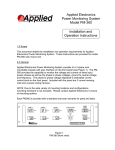
MST MODEL 5700 - S1
AIRLINE "CO" MONITORING AND
LOW PRESSURE WARNING SYSTEM
MANUAL
******************************************************************************
WARNING: Do not attempt to operate this equipment without first reading and
understanding the service manual enclosed with this device.
******************************************************************************
06/09
2
CONTENTS
SPECIFICATIONS . . . . . . . . . . . . . . . . . . . . . . . . . . . . . . . . . . . . . . . . . . . . . . . . . . . . . . . . . . . . 3
GENERAL DESCRIPTION . . . . . . . . . . . . . . . . . . . . . . . . . . . . . . . . . . . . . . . . . . . . . . . . . . . . . 4
GENERAL OPERATIONS . . . . . . . . . . . . . . . . . . . . . . . . . . . . . . . . . . . . . . . . . . . . . . . . . . . . . . 4
MST'S AIRLINE "CO" SYSTEM
INITIAL INSTALLATION
AND START-UP . . . . . . . . . . . . . . . . . . . . . . . . . . . . . . . . . . . . . . . . . . . . . . . . . . . . . . . . . . . . . . 7
MST'S AIRLINE "CO" SYSTEM
GENERAL OPERATION AND MAINTENANCE . . . . . . . . . . . . . . . . . . . . . . . . . . . . . . . . . . . 9
RECORD KEEPING . . . . . . . . . . . . . . . . . . . . . . . . . . . . . . . . . . . . . . . . . . . . . . . . . . . . . . . . . . 10
SERVICE RECORD . . . . . . . . . . . . . . . . . . . . . . . . . . . . . . . . . . . . . . . . . . . . . . . . . . . . . . . . . . 11
3
SPECIFICATIONS
MST AIRLINE "CO" MONITORING SYSTEM
MST MODEL 5700 - S1
SIZE:
16"W X 16"H X ½" THICK
(406mm X 406mm X 13mm)
WEIGHT:
6.5 LBS (2.9 KG)
OPERATING PRESSURE (MAX.):
SENSOR TYPE:
100 PSI (6.9 BAR)
ELECTROCHEMICAL
RANGE:
0-199 PPM CO
ACCURACY:
+/-5% OF READING
ALARM-TYPE:
MONITOR PIEZOELECTRIC - 85 dB(A) AT (1) FT.
(8008403 REMOTE ALARM 119 dB (A) AT (10) FT.)
ALARM LEVEL SETTING:
AMBIENT OPERATING
TEMPERATURE RANGE:
LOW PRESSURE: USER ADJUSTABLE
FACTORY SET AT 20 PSI
MONITOR FACTORY SETTING: 10 PPM (US)
5 PPM (CANADA)
32 - 104o F (0 - 40 o C)
OTHER FEATURES
ADJUSTABLE LOW PRESSURE WARNING SYSTEM
BETWEEN 10 AND 100 PSI ADJUSTABLE SAMPLE FLOW METER
RED LED ALARM INDICATOR
120 VAC (12 VDC OUTPUT) POWER ADAPTER
4
GENERAL DESCRIPTION
The MST Airline Carbon Monoxide and Low Pressure Warning System is designed to take a
continuous air source sample and monitor for levels of Carbon Monoxide and to alarm if either
carbon monoxide, above the preset maximum permissible level is encountered, or if the airline
pressure falls below a preset low pressure set point. The system is mounted on a panel for wall
mounting.
GENERAL OPERATION
(Refer to Figure No. 1)
Initially the 120 VAC continuous power adapter (A) must be plugged into a dedicated 120 VAC
outlet to provide power to the system. NOTE: If monitor’s switch (B) is turned on before the
minimum pressure is applied at (C), the low pressure warning system will activate the alarm system.
The air source to be monitored will enter through the system’s inlet at (C). After air source has been
connected to the system’s inlet, adjust the black flow control knob of the Flowmeter (D) to meter
the correct sample air to the CO Monitor’s (E) electrochemical CO sensor (F). If the CO content in
the sample air exceeds the monitor’s CO alarm setting, the monitor’s internal buzzer (G), red
indicator LED (H) and the Remote Audible Alarm (I) will be energized. During normal operation,
should a low pressure situation occur, only the Remote Audible Alarm (I) will sound.
FIGURE NO. 1
5
INSTALLATION AND ADJUSTMENT
Locate a suitable place to mount or install the Model 5700-S1 and secure the panel utilizing the
mounting holes on the corners and attach the air supply (100 psi max.) to the 3/8" FPT inlet located
at “C” in Figure No. 1. DO NOT APPLY EXCESS PRESSURE to the aluminum manifold unless
supporting the manifold with another wrench. Should the factory preset level (20 psi) be
satisfactory, the unit is ready to operate by pressurizing the system and turning the “ON-OFF” Switch
on the 5700 CO Monitor to the “ON” position. The CO Monitor must now be calibrated to assure
proper operation (see Monitor’s Manual). To prevent the audible external alarm from sounding
when calibrating the monitor, unplug the alarm from the monitor. Be sure to reattach the alarm when
calibration is completed.
Should you need to adjust the switch to some other setting, loosen the four (4) screws located at the
four corners of the housing and carefully lift off front cover to expose the pressure switch and
internal wiring (see Figure No. 2). Locate the white adjustment dial located at the base of the
pressure switch. Note: The numbers located on the adjustment dial are for approximation only - DO
NOT assume the setting noted on the dial is the alarm set pressure. Adjust the system pressure to
alarm set point level desired and turn the adjustment dial until the unit just activates the alarm.
Slowly increase the system pressure above this setting until the alarm stops. Slowly lower the
system pressure until alarm activates. Note the system pressure, and if this is the desired alarm set
point, the unit is ready for operation. Readjust if necessary and replace front cover.
Warning: The Alarm Set Point should be verified prior to each use to assure the unit is
operating properly and no one has tampered with the device.
6
MST, Inc. strongly recommends that a complete safety program be instated to ensure that the
respiratory air is in compliance with all OSHA/CSA standards and other applicable laws
regulating the use of supplied air respiratory systems. MST, Inc. recommends that the air
quality be tested upon installation and periodically re-tested to ensure that the minimum
requirements for breathing air are maintained.
MST, Inc. will not assume any liability for accidents or personal injury resulting from the
improper use of this equipment. Service on this equipment should only be performed by
qualified personnel. This system is to be used only by trained qualified personnel in
accordance with a respiratory program as outlined in OSHA Regulation 29 CFR 1910.134 (b).
7
MST'S AIRLINE "CO" MONITORING SYSTEM INITIAL
INSTALLATION AND START-UP
(Refer to Figure No. 1)
1) SUPPLIED AIR HOOK-UP - MST Unit’s inlet is supplied with 3/8" NPT female threads for
customer hook-up (C). MST suggests the supplied air be regulated to a maximum pressure of 100
psi and free of water and/or oil and dirt particles.
2) POWER MONITOR AND CALIBRATE -Plug in the 120 VAC continuous power adapter (A)
into a dedicated 120 VAC outlet. At this time, to avoid hearing the loud Remote Audible Alarm (I),
the alarm can be disconnected during the calibration procedure by disconnecting alarm at (J).
WARNING: Be sure to reconnect the Remote Audible Alarm when calibration is complete. After
a five (5) minute warm-up period, calibrate the monitor according to the MST Monitor Manual.
3) CALIBRATION GAS REQUIREMENTS - Zero Gas: Nitrogen or Air, free of “CO”. Span Gas:
95 PPM of “CO” concentration in air. NOTE: DO NOT USE GAS THAT IS INTENDED TO
CALIBRATE MULTIPLE SENSOR GAS MONITORS, EVEN IF THE “CO” CONCENTRATION
IS CORRECT. Calibration gas flow to monitor should be 1.0 SCFH (472 ml/min).
4) EXTREME TEMPERATURE CHANGES - Avoid; the MST 5700 CO Monitor best performs
at an ambient temperature range of 32 - 104 F (0-40 C). Always calibrate the monitor after it has
stabilized in the surrounding temperature where the system is to be used.
5) LOW PRESSURE WARNING SYSTEM AND MONITOR SAMPLE FLOW ADJUSTMENTS After the monitor has been calibrated, turn off the monitor and reconnect the Remote Audible Alarm
(I). Turn the black flow control knob of flowmeter (D) clockwise to make sure it is turned off.
Connect your compressed air to the inlet (C). Now carefully turn the black flow control knob
counter-clockwise to open the valve. Open just enough to keep the black ball floating about midrange in the green “safe zone” area of the flow meter (refer to Figure No. 2).
8
******************************************************************************
WARNING : SERIOUS INJURY could result if the AIR SAMPLE METERING VALVE is
not properly adjusted. Proper sample air flow to ‘CO’ monitor is required for monitor to give
correct ‘CO’ level readout.
******************************************************************************
To adjust the low pressure setting, an external regulator will be required to pressurize the system to
the low pressure set point. For example, if the lowest pressure allowed for your respiratory system
is 50 psi, then adjust the external regulator to 50 psi and using the procedure outlined on page 5 of
this manual, adjust the new set point to 50 psi. Recheck pressure setting by turning the external
regulator above the set point to deactivate the alarm, and slowly reduce pressure until alarm
activates. Note if correct pressure was reached when alarm activated and readjust if required.
FIGURE NO. 2
9
MST AIRLINE "CO" MONITORING SYSTEM
GENERAL OPERATION AND MAINTENANCE
******************************************************************************
WARNING: If the Monitor's alarm should sound, remove mask or hood immediately and
move to a safe breathable atmosphere. Have a proper qualified personnel examine air system
and make the appropriate corrections before using again.
******************************************************************************
1) MONITOR ALARM CONDITION - The monitor will alarm due to one or more of the
following conditions:
a) Monitor is out of calibration. The Monitor should be calibrated monthly if used
continuously and prior to use if used on a non-continuous basis. Calibrate Monitor as
outlined in the MST Monitor Manual.
b) If the Monitor can be and is calibrated, but the alarm still sounds, excessive CARBON
MONOXIDE IS PRESENT IN YOUR AIR LINE. REMOVE MASK OR HOOD
IMMEDIATELY AND MOVE TO A SAFE BREATHABLE ATMOSPHERE. CHECK
AIR SYSTEM TO CORRECT PROBLEM BEFORE USING AGAIN.
c) If the Monitor can not be calibrated, the Carbon Monoxide Sensor may require
replacement. See MST MONITOR MANUAL for replacement instructions and
other trouble shooting information. The MST MONITOR has a (1) year warranty.
All warranty work must be performed at factory.
d) If the Monitor was calibrated in a surrounding temperature other than where the
system was being used and the temperature difference was 36o F (20o C) or greater,
the Monitor may give a false alarm due to its characteristics. Always calibrate the
Monitor in the temperature conditions where the monitor is to be used in. Monitor
best performs at temperature range of 32 to 104o F (0 to 40o C).
e) Inlet air pressure below low pressure set point is encountered. NOTE: Only the external
alarm will sound. Increase inlet pressure to required pressure for your respirators (or readjust low pressure set point to the correct pressure requirement of your respiratory
system).
2) MONITOR "NORMAL" MODE - The Monitor's "NORMAL GREEN LED" light will be on full
bright from 0-9 PPM of carbon monoxide (or 0-5 PPM in Canda) and the "ALARM RED LED"
light will be faintly blinking while the “Low Battery Amber LED” is off.
10
3) MONITOR "ALARM" MODE - If carbon monoxide concentrations exceeds the alarm point
(factory set at 10 PPM or 5 PPM in Canada), the "ALARM RED LED" light will come on full
bright, the "NORMAL GREEN LED" light will be off and the audible alarm will sound. Also
the Remote Audible Alarm will sound.
4) CONTAMINATED AIR SUPPLY - If water and/or oil is visibly seen in the flow meter
and/or sample tube to MST Monitor, excessive water and/or oil is present in the supplied
air. These contaminates should be coalesced out prior to inlet of MST's "CO" Monitoring
System to eliminate clogging of MST's Flow Meter and or "CO" Sensor.
RECORD KEEPING
Record all periodical air quality checks, monitor calibration date and any other service performed
on the MST "CO" Monitoring System.
MST, INC. SHALL NOT BE LIABLE FOR ANY INJURY LOSS OF DAMAGE,
(DIRECT OR CONSEQUENTIAL), ARISING OUT OF THE USE OF OR THE
INABILITY TO USE THIS PRODUCT, BEYOND THE REPLACEMENT OF THE
DEFECTIVE MATERIALS OR WORKMANSHIP. USER OF SUPPLIED AIR
RESPIRATORS SHOULD EVALUATE THEIR OWN PARTICULAR APPLICATION
AND PERFORM THEIR OWN TESTS FOR AIR QUALITY TO DETERMINE THE
SUITABILITY FOR USE OF THIS PRODUCT.
For further information, or questions about service or maintenance care of this unit, contact your
local distributor or MST, Inc. @ (800) 542-6646.
11
SERVICE RECORD
MST AIRLINE "CO" MONITORING SYSTEM
MODEL 5700 - S1
DATE OF SERVICE
SERVICE PERFORMED