1
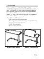
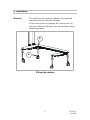
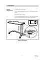
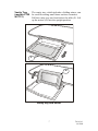
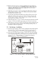
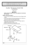
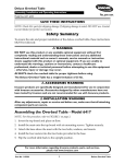
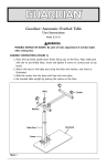
ENTERPRISE™
OVERBED & OVERCHAIR TABLES
MODELS
PT10, PT11, PT20, PT21
SERVICE MANUAL
Build Level 04
Document Reference: 746-414
Contents
1. Introduction ............................................................................. 3
2. Assembly ................................................................................. 4
3. Operation ................................................................................. 5
4. Cleaning and Maintenance ..................................................... 7
5. Servicing Instructions............................................................. 9
6. Warranty and Service............................................................ 13
7. Dimensions and Data............................................................ 14
Warnings and Cautions
WARNINGS given in this manual identify possible hazards in
procedures or conditions, which if not correctly followed, could result in
death, injury or other serious adverse reactions.
Cautions given in this manual identify possible hazards in procedures or
conditions, which if not correctly followed, could result in equipment
damage or failure.
WARNING
The carer should ensure the table is correctly positioned and
adjusted to allow the patient to use it safely and comfortably.
Do not lean or sit on the table.
Do not exceed the Safe Working Load
of 25kg evenly distributed.
!
Caution
Take care when moving the table over rough or uneven
surfaces. Lift the table over large ridges and wide gaps.
2
746-414-1
09/2008
1. Introduction
The Huntleigh Healthcare PT10, PT11, PT20 and PT21 are overbed /
overchair tables that provide patients with a firm, flat surface suitable for
eating, writing, reading, etc. Single-column construction and adjustable
height makes them suitable for use with most types of beds and chairs.
Models PT10 and PT20 have a fixed one-piece top surface.
Models PT11 and PT21 have a two-piece top surface with adjustable tilt.
Models PT20 and PT21 have a vanity tray fitted below the table.
All models have the following features:
• Wipe-clean top with raised moulded edges
• Base design allows the table to be used over either a bed or a chair
• Gas spring assisted height adjustment
• Castors for ease of mobility
• Range of colours and finishes
Model PT10 with fixed top
Model PT11 with tilting top
3
746-414-1
09/2008
2. Assembly
General
The table may be supplied with the castors packed
separately to prevent transit damage.
Fit the four castors by pushing the castor stems (A)
into the sockets on the table base (B) until the castors
lock into position.
B
A
Fitting the castors
4
746-414-1
09/2008
3. Operation
Height
Adjustment
To lower the table height:
Lift the height adjustment lever (C) and push the table
down.
To raise the table height:
Lift the height adjustment lever (C) and allow the table
to rise under the action of the internal gas spring.
C
Height adjustment
5
746-414-1
09/2008
The tilt angle of the table may be adjusted to one of six
Tilt
positions.
Adjustment
(models PT11
To increase the tilt angle:
& PT21)
Hold the edge of the table as shown (D). Lift the table
until the ratchet (E) engages at the required position.
To reduce the tilt angle:
Hold the edge of the table as shown (D). Lift the table
as far as it will go, then lower it back to the flat
position.
D
E
Tilt adjustment
WARNING
Take care not to trap hands or fingers between the fixed and
movable parts of the table
6
746-414-1
09/2008
The vanity tray, which includes a folding mirror, can
Vanity Tray
(models PT20 be used for storing small items such as cosmetics.
& PT21)
Pull the vanity tray out from below the table (F). Lift
up the mirror (G) into the upright position.
F
G
Vanity tray and mirror
7
746-414-1
09/2008
4. Cleaning and Maintenance
Cleaning
Wearing suitable protective clothing, clean all surfaces
with a disposable cloth soaked in a neutral detergent and
hand hot water.
Start by cleaning the upper sections of the table and work
along all horizontal surfaces. Work methodically towards
the lower sections of the table and clean the castors last.
Take extra care to clean areas that may trap dust or dirt.
Rinse with clean water and dry with disposable paper
towels.
Disinfecting
After cleaning the table as described above, wipe all
surfaces with sodium dichloroisocyanurate (NaDCC) at a
concentration of 1,000 parts per million (0.1%) of
available chlorine.
In the case of pooling body fluids, e.g. blood, the
concentration of NaDCC should be increased to 10,000
parts per million (1%) of available chlorine.
Caution
Avoid excessive wetting of the product, particularly the table top
Do not use abrasive compounds or pads
Do not use phenol-based disinfectants
Maintenance
The following preventive maintenance procedures should
be carried out at intervals of 12 months. All service or
repair activities must be carried out by properly qualified
and trained persons approved by Huntleigh Healthcare.
Check that the height adjustment mechanism functions
smoothly and that the table locks securely in position over
the full range of table height.
Make sure all four castors are securely fixed to the base
and that they swivel and rotate freely. Remove any debris
that may have been picked up by the wheels.
Models PT11 & PT21 only: check that the table locks
securely at each tilt position.
8
746-414-1
09/2008
5. Servicing Instructions
These tables are designed to provide years of service, however after
prolonged or improper use the castors, gas spring, column rollers or tilt
ratchet mechanism (Rastomat) may become worn or damaged. This
chapter contains instructions for replacing these items. No special tools
are required.
In the following procedures, numbers in bracket refer to the
item identifier on the drawings in Appendix A, e.g. (1-12)
indicates item 12 on Sheet 1.
WARNING
Use only replacement spare parts that are approved by
Huntleigh Healthcare
Dispose of waste materials and components safely in
accordance with all applicable national and local regulations
5.1
Castors – Replacement
Using a suitable flat bladed tool, e.g. a screwdriver, lever the faulty castor
(1-18)/(2-18) out of the base casting. Fit the new castor by pushing the
castor stem into the hole in the base until it “clicks” into position.
5.2
Gas Spring – Removal
WARNING
The gas spring contains air and oil under high pressure - do
not attempt to open it
Do not push the piston fully into the gas spring body as this
may damage the seal and cause oil to be expelled
a) Raise the table to maximum height. Support the table frame (1-6)/(26) on a suitable surface (e.g. another table) from below.
b) PT10/PT20 only: prise off the four screw covers (1-9) on the
underside of the table frame. Remove the four screws (1-8), together
with the screw cover bases (1-7), and lift off the table top.
c) PT11/PT21 only: prise off the two screw covers (2-10) on the
underside of the table frame. Remove the two screws (2-9), together
with the screw cover bases (2-8), and lift off the fixed table section.
9
746-414-1
09/2008
d) Remove the four screws (1-5)/(2-5) attaching the outer column (111)/(2-11) to the table frame. WARNING: Do not allow the outer
column to fall when the screws are removed. Lower the outer
column and rest it on the base.
e) Undo the two screws (1-1)/(2-1) securing the table frame to the gas
spring support casting (1-26)/(2-32). Remove the base and column
assembly from the table frame.
f) Lay the base and column assembly on its side to allow access to the
underside. Undo the four screws (1-15)/(2-15) below the base and
slide the inner column (1-20)/(2-20) and outer column off the base,
exposing the gas spring (1-24)/(2-30).
g) Undo the large nut (1-17)/(2-17) below the base and retain the serrated
washer (1-16)/(2-16). Pull the gas spring out of the hole in the base.
h) Undo the nut (1-25)/(2-31) at the top of the gas spring and unscrew the
gas spring support casting. Dispose of the used gas spring safely, in
accordance with local regulations.
5.3
Gas Spring – Installation
a) Fit the new gas spring (1-24)/(2-30) by pushing the thread through the
hole in the base. Attach the gas spring with the serrated washer (116)/(2-16) and large nut (1-17)/(2-17) on the underside of the base.
b) Screw the gas spring support casting (1-26)/(2-32) onto the threaded
end of the gas spring piston, until the piston just protrudes above the
casting (X = 0.5 - 1.5mm in Figure 5-1). Secure the casting by
tightening the nut (1-25)/(2-31) underneath it.
(1-26)
(2-32)
(1-24)
(2-30)
(1-25)
(2-31)
Figure 5-1 Gas spring support casting adjustment
10
746-414-1
09/2008
c) Slide the column assembly over the gas spring. Secure the inner
column (1-20)/(2-20) to the base with the four hex head screws.
d) Position the base and column assembly upright below the table frame
(1-6)/(2-6). Secure the gas spring casting to the frame and release
handle assembly using two screws (1-1)/(2-1). Lift up the outer
column (1-11)/(2-11) and attach it to the table frame using four bolts
(1-5)/(2-5).
e) PT10/PT20 only: replace the table top on the frame. Secure from
below with four screws (1-8) with screw cover bases (1-7) attached.
Replace the four screw covers (1-9).
f) PT11/PT21 only: replace the fixed part of the table top on the frame.
Secure from below with two screws (2-9) with screw cover bases (2-8)
attached. Replace the screw covers (2-10).
5.4
Roller Assembly – Replacement
a) Disassemble the table far enough to access the column assembly, as
given in Section 5.2, paragraphs a) to f).
b) Slide the inner column (1-20)/(2-20) out of the outer column (111)/(2-11), just far enough to expose the roller assemblies (1-22 & 123)/(2-22 & 2-23). Remove two screws (1-21)/(2-21) to detach the
roller assembly from the inner column.
c) Fit the new roller assemblies (1-22 & 1-23)/(2-22 & 2-23) and secure
each with two screws (1-21)/(2-21). N.B. make sure each roller
assembly is fitted on the correct side of the inner column. Do not overtighten the fixing screws – the rollers should rotate freely.
d) Slide the inner column into the outer column. Reassemble the table as
given in Section 5.3, paragraphs c) to f).
5.5
Rastomat Assembly – Replacement (PT11 & PT21 only)
a) Prise off and discard the capped starlock washer (2-29) used to attach
the Rastomat assembly (2-28) to the table frame (2-6).
b) Undo two Ejot screws (2-27) to release the Rastomat assembly from
the tilting table section.
c) Fitting of the new Rastomat assembly is the reverse of the removal
procedure. Use a new capped starlock washer (2-29) to secure the
Rastomat assembly to the table frame.
11
746-414-1
09/2008
5.5
Vanity Tray Assembly – Replacement (PT20 & PT21 only)
a) Remove the four self tapping screws (05-6) that attach the tray runners
(5-2) and (5-4) to the table frame (1-6)/(2-6).
b) Replacement is the reverse of the removal procedure. N.B. make sure
the tray runners are replaced in the correct positions.
12
746-414-1
09/2008
6. Warranty and Service
Huntleigh Healthcare’s standard terms and conditions apply to all sales.
A copy is available on request. These contain full details of warranty
terms and do not limit the statutory rights of the consumer.
For service, maintenance and any questions regarding this, or any other
Huntleigh product, please contact:
Huntleigh Healthcare Ltd.
310-312 Dallow Road
Luton
Bedfordshire
LU1 1TD
Telephone
Fax
E-mail
Internet
01582 413104
01582 459100
[email protected]
www.arjohuntleigh.com
13
746-414-1
09/2008
7. Dimensions and Data
PT10, PT11, PT20 and PT21 Overbed / Overchair Tables
Table top dimensions
90 x 42 cm max.
Height adjustment range
71 to 108 cm
Tilt angles (approx.)
0°/24°/31°/37°/42°/47° ( PT11 & PT21 only)
Product weight (approx.)
17 kg
Safe working load
25 kg
evenly distributed
14
!
746-414-1
09/2008
APPENDIX A - ASSEMBLY SPARES MANUAL
The Assembly Spares Manual is for the identification and requisition of
replaceable parts. It contains assembly drawings of the equipment and
sub-assemblies. Each drawing sheet is accompanied by its related parts
list.
Refer to the servicing instructions given in Chapter 7 to identify the
applicable drawing sheet number. Find the part on the drawing and note
the item number, which is given in a balloon, e.g. c. Refer to the related
parts list for information regarding the part.
Sometimes a number of identical parts may appear in different locations
but only one will be identified with a balloon. The number in the “Qty”
column of the parts list indicates the total number of times that the part
appears in the drawing.
When a part has optional variations, the last column(s) of the parts list
refers to a separate drawing sheet defining the choices.
15
746-414-1
09/2008
Form 130/2
Service Manual Amendments Sheet
Document Ref. 746-414
Product – Overbed Tables PT10, PT11, PT20 & PT21
Build
Level
Mod Note
Date
Serial No.
2
4688
22.02.07
879838
3
4713
04.04.07
891254
4
5039
08.10.08
Form 130-2 Service Manual Amendments Sheet_PT10 etc.doc
Sheet No.
Drawing No.
Issue
1
2
1
2
5
814.87
814.25
814.635
814.87
814.25
814.655
2
2
3
3
3
1
10/10/2008