1
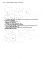
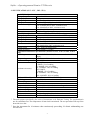
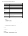
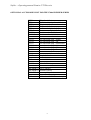
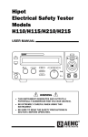
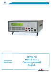
Premier
27xxA
Revision : B
PREMIER 27xxA SERIES OPERATING MANUAL
efelec
Parc d'Activités du Mandinet - 19, rue des Campanules
77185 LOGNES - FRANCE
Téléphone : 33.1.64.11.83.40
Télécopie : 33.1.60.17.35.01
E-mail
: [email protected]
http
: www.sefelec.com
Sefelec – Operating manual Premier 27XXA series
WARRANTY:
SEFELEC warrants that units are free from defects in material and workmanship.
SEFELEC warrants also that, when properly used, that units will perform in
accordance with specifications of this manual.
If within one year after original delivery it is found not to meet this standard, it will
be repaired at no charge in SEFELEC service facility in Lognes (France).
Changes in the unit not approved by SEFELEC will cancel this warranty.
SEFELEC will not be liable for any indirect damages resulting of the use of the
unit.
This warranty is in lieu of all other warranties.
2
Sefelec – Operating manual Premier 27XXA series
CONTENTS
PAGE
1 PRODUCT INTRODUCTION .....................................................................................................................................5
1.1 Description............................................................................................................................................................5
1.2 Features ................................................................................................................................................................6
3. PRECAUTIONS BEFORE OPERATION ...............................................................................................................10
3.1 SAFETY INFORMATION................................................................................................................................................10
3.2 UNPACKING THE INSTRUMENT ...................................................................................................................................11
4. PANEL INTRODUCTION.........................................................................................................................................12
z
z
Front panel :.................................................................................................................................................12
Rear panel : ..................................................................................................................................................14
5. OPERATION METHOD............................................................................................................................................16
5-1. Main Display LCD ............................................................................................................................................16
5-2. Prepare the PREMIER SERIES for Use .........................................................................................................18
5-3. Structure of storage steps..................................................................................................................................25
5-4. Menu parameter setup ......................................................................................................................................26
6. FUNCTIONALITY OF REMOTE INTERFACE....................................................................................................30
7. MAINTENANCE ........................................................................................................................................................31
7.1 PRELIMINARY .................................................................................................................................................31
7.2 INSTRUMENT RETURN .................................................................................................................................31
7.3
MAINTENANCE .........................................................................................................................................31
7.4 CLEANING ........................................................................................................................................................32
7.5 CALIBRATION..................................................................................................................................................32
3
Sefelec – Operating manual Premier 27XXA series
Warning : This unit must be used by qualified people. Every precautions for the
use of units connected to the main must be taken during its use. In particular,
this unit must be connected to earth.
The specifications of this manual, the correct operation of the unit as well as the operator’s
security are guaranteed only when the supplied accessories are used. The measurement probes
can include limitation or protective elements, therefore it is forbidden to modify without
written agreement from SEFELEC company.
In case of use under other conditions than the one specified in this manual, the security of the
user will be in danger.
MEANING OF THE DIFFERENT SYMBOLS ON THE INSTRUMENT
Warning (See document attached)
Warning, risk of electric chock.
DC voltage.
AC and DC voltages.
AC voltage.
Earth connection.
4
Sefelec – Operating manual Premier 27XXA series
1 PRODUCT INTRODUCTION
1.1 Description
The PREMIER 2700A series of Electrical Safety Tester (EST) is designed for AD/DC Withstanding
Voltage Test and Insulation Resistance Test(IR) for providing a safe and accurate test environment for
the operator. With thoughtful design described in 1-2. Feature to insure a safe operation of high voltage
test and protect user from hazardous impact.
The Electrical Safety Testers comply with the requirement of the electrical equipment & appliance
control ordinances and EN, VDE, JIS, CSA, UL, BS and other standards as well. The testers can be used
for withstanding voltage test of the various types of electrical and equipment and components.
The PREMIER 2700A series is based on the family of Sefelec withstanding voltage tester. It
includes AC withstanding voltage test, DC withstanding voltage test, insulation resistance test and Ground
Bond test (GB).
Function
Model
Premier 2705A
AC
DC
IR
GB
X
Premier 2715A
X
Premier 2725A
X
Premier 2735A
X
Premier 2740A
X
Premier 2745A
X
X
X
X
X
X
X
5
X
X
Sefelec – Operating manual Premier 27XXA series
1.2 Features
The PREMIER 2700A series offer several other features:
1) No load setup of trip current and output voltage.
A safe way to setup trip current and output voltage without high voltage activated.
2) A large 24×2 character LCD with adjustable LED backlight.
Provide a clear display about test parameters, which including group, step, mode, status, output
voltage, trip current and test time.
3) Easily and quickly setup by front panel.
A user-friendly interface provides user with an easy and quick way to set all parameters.
4) Electronic ramping and testing
Digital controlled ramping time and testing time.
5) Line and load regulation
Linear amplifier and feedback-control maintain output voltage disregard of the variation of load.
6) Selectable output frequency
50/60 Hz is selectable by utility setup.
7) Adjustable ARC detect level
ARC detect level could be setup by utility setup.
8) 10 groups of storage and each group has 16 steps
Total 10 storage groups provided for testing of different products, and each group has 16 steps.
9) Adjustable output voltage during test
A special test mode in step 0, user could adjust the output voltage during testing
10)Flashing high voltage indicator
A flashing red LED indicates dangerous situation during high voltage output is activated.
11)PLC remote control
The 9-pin interface provides inputs ( START, RESET ) and outputs ( TEST, PASS, FAIL ).
12)Data lock function
Front panel could be locked or unlocked by utility setup.
13)Earth Check function
Check the continuity of earth ground in the power inlet before testing.
14)Interlock function
No High voltage on the output if the INTERLOCK terminals are not shortened together .
15) RS-232 and GPIB Interface
The RS-232 and GPIB interface enables remote control operation and signal
processing via a PC. (Option)
16) R/P Output
The output terminal located on the rear panel. (Option)
6
Sefelec – Operating manual Premier 27XXA series
2. SPECIFICATION (15°C~35°C , RH <75%)
1) AC Hi-Pot Specifications
Voltage Range
0.100~5.000kV
Voltage Step
5V/step
Voltage Regulation
1% of reading + 5 counts
Voltage Accuracy
1% of reading + 10V (above 500V)
Current Sourcing*
30~40mA(above 500V, maximum test time: 180 sec)
0.10~29.99mA(above 500V, continuous test)
0.10~10mA(below 500V, continuous test)
Current Limit
0.10~40mA, 0.02mA/step
Current Accuracy
1% of reading + 5 counts
2) DC Hi-Pot Specifications (Premier 2715A, 2735A, 2745A only)
Voltage Range
0.100~6.000kV (Pole + connected to the HT output)
Voltage Step
5V/step
Voltage Regulation
1% of reading + 5 counts
Voltage Accuracy
1% of reading + 10V (above 500V)
0.10~10.00mA(above
500V, continuous test)
Max Current
0.10~2mA(below 500V, continuous test)
Current Limit
0.10 ~ 10 mA, 0.02mA/Stepp
Current Accuracy
1% of reading + 5 counts
3) Insulation Resistance Specifications (Premier 2725A, 2735A, 2740A, 2745A
only)
DC Voltage
50V/100V/500V/1000V (Pole + connected to the HT
output)
Output voltage accuracy +/-(3.5% + 40 V) in relation to the set point
Resistance Range
1~9999MΩ
50V/100V:
1~50MΩ : 5% of reading
51~200MΩ : 10% of reading
201~1990MΩ : 20% of reading
Resistance Accuracy
500V/1000V:
1~500MΩ : 5% of reading
501~2000MΩ : 10% of reading
2001~9999MΩ : 20% of reading
4) Ground Bond Specifications (Premier 2740A, 2745A only)
Test Voltage
Max. 8V(DC)
Current Range
3~42A
Current Resolution
0.02A
Output current Accuracy +/-(1% + 500 mA) in relation to reading value
Current reading accuracy +/-(1% + 200 mA) in relation to
Resistance Range
0~600mΩ
Resistance Resolution
0.1m
Resistance Accuracy
1% of reading +10 mΩ in relation to the true value
Test Method
Four Terminals Test Mode
* The main purpose provided by the series of instruments is for Puncture Testing. The specification is
not for continuous test. The temperature of heat-sink is monitored. The test procedure will stop if the
heat-sink is too hot.
* Stop the instrument for 10 minutes when continuously proceeding 30~40mA withstanding test
for one hour.
7
Sefelec – Operating manual Premier 27XXA series
5) Continuity Check Specifications (exepted 2740A and 2745A)
Test Current
0.1A
Current Accuracy
10%
Detect Accuracy
0.1Ω @1Ω
6) ARC Detect
Detect Current
40 level (1~40mA)
7) Storage
Groups
10
Steps per Group
16
8) PLC Interface
Type of terminal
9-pin D-sub connector
Output breakdown
±350V
voltage
Continuous load current ±100mA
9) Interface
RS-232
GPIB
10) General
Power Source
Accessories
Dimension
Weigh
Option
Option
AC100V, 120V, 220V, 230V±10% 50/60Hz
× 1 mains cord
x 1 15pins connector
x1 Instruction manual
446(L) × 330(W) × 149(H) (m/m)
Approx. 14.9 kgs
• The instrument must be used inside, in horizontal position or on tripode.
• Temperature :
• In storage : -10°C to +60°C.
• In operation : 0°C to +45°C.
• Accuracy is rated after half an hour of warm up and for a relative humidity < 50%.
• Altitude : up to 2000 meters
• Max. humidity rate : 80% for a temperature of 31°C.
Over voltage category :
• CAT II.
Rate of pollution :
• Pollution 2 : Occasional conductive pollution only by condensation.
Safety class :
• Class I instrument : Earth protection by mains connection.
8
Sefelec – Operating manual Premier 27XXA series
OPTIONNAL ACCESSORIES LIST FOR THE 2700A PREMIER SERIES
TE75
TE76
TE77
TE77-5
TE78
TE78-5
CO221
CO221-5
HV probe (l=2m)
HV cable without probe (l=5m)
HV pistol (l=2m)
HV pistol (l=5m)
Remote control pistol (l=2m)
Remote control pistol (l=5m)
Pistol return lead (l=2m)
Pistol return lead (l=5m)
CO215
CO216
CO217
CO218
CO219
CO220
Box with mains plug : Schuko
Box with mains plug : UK
Box with mains plug : Switzerland
Box with mains plug : Italia
Box with mains plug : USA
Box with mains plug : France
AO16
AO17
Remote control foot switch
Simple , 2 hands remote control
KRPremier
Rack 19" 3U kit
CO222
RED/GREEN lamp
PREMIER-01 RS232 (option)
PREMIER-02 IEEE488 (option)
PREMIER-03 Rear output (option)
CalPremier
Calibration AC/DC/IR/continuity kit
9
Sefelec – Operating manual Premier 27XXA series
3. PRECAUTIONS BEFORE OPERATION
Warning : This unit must be used by qualified people. Every precautions for the
use of units connected to the main must be taken during its use. In particular,
this unit must be connected to earth.
The specifications of this manual, the correct operation of the unit as well as the operator’s
security are guaranteed only when the supplied accessories are used. The measurement probes
( TE75 , TE76 , TE77, …) can include limitation or protective elements, therefore it is
forbidden to modify without written agreement from SEFELEC company.
In case of use under other conditions than the one specified in this manual, the security of the
user will be in danger.
3.1 Safety information
Please read and follow these important safety instructions:
•
Read the safety information at the beginning of this manual before operating the Premier series
• Make the necessary electrical safety connection checks. In particular, select the correct line voltage
and make sure that the correct fuse is installed. Incorrect voltage or fuse selection present both an
electrical safety and a fire hazard. Ensure that the rear panel fan is operating and that the vent is not
blocked.
• When connecting to an electrical supply mains supply, the mains cord provided with the equipment
should be used, and connected only to a mains supply with a suitable earth connection. Under no
circumstance should the equipment be operated with earth disconnected.
• Working place :the working place must be isolated and when the high voltage is proceeding, it
should be alerted with a warning of dangerous for special caution.
•
Checking the Line Voltage
The instrument can be applied any kind of line voltage shown in the table below. Before connecting
the power plug to an AC line outlet, make sure the voltage selector of the rear panel is set to the
correct position corresponding to the line voltage. It might be damaged the instrument if connected to
the wrong AC line voltage.
10
Sefelec – Operating manual Premier 27XXA series
WARNING. To avoid electrical shock the power cord protective grounding conductor must be
connected to ground.
WARNING. To avoid personal injury, disconnect the power cord before removing the fuse holder.
When line voltages are changed, replace the required fuses shown as below:
Line voltage
Range
Fuse
Line voltage
Range
Fuse
100V
120V
90-110V
108-132V
T 7.0A 250V
220V
230V
198-242V
207-250V
T 4.0A 250V
3.2 Unpacking the instrument
When you unpack the Premier series unit , check that the following items are present before starting
to use the unit:
•
1x
Premier series unit
•
1x
Mains Cord
•
1x
15 pins connector
•
1x
Operating manual
Please contact the Sefelec Customer Support Team immediately if any of these items are missing or
damaged.
Operator’s Precaution
(1) With high output voltage and current of the Dielectric strength tester, only qualified person can
operate the tester in order to avoid fatal electric shock.
(2) On-job training is required for operator to better use the tester smoothly and safely.
(3) The operator is prohibited to dress with metal ornaments or wear metal decoration in order to avoid
electric shock.
(4) The person with cardiac or wear a pacemaker must not to operate the tester.
Secure Testing
Never operate the tester in the place with electric circuit device around.
The earth lead should be well connected in accordance with instruction. The Return Lead has to be
connected to the tested object first before linking up test probe. Do not plug the high voltage test
probe to the high voltage output terminal before doing the testing. Also, do not touch the electric
conductor of test probe and the operator has to fully control the power on/off by using switch or
remote control, which should not be lay aside carelessly.
WARNING: During the testing, do not touch the tested object or any other connected
objects.
11
Sefelec – Operating manual Premier 27XXA series
4. PANEL INTRODUCTION
z
Front panel :
12
Sefelec – Operating manual Premier 27XXA series
1 Model Number
2 FAIL Indicator
LED
3 PASS Indicator
LED
4 CAUTION
Indicator LED
Display
5 Main
LCD
6 START Button
7 RESET Button
Model number and description
The red LED indicates failure of test procedure
The green LED indicates pass of test procedure
During test the red LED will flash to indicate
dangerous.
The LCD displays all message about test
procedure.
Press the green button to start a test procedure.
Press the red button to reset/stop a test
procedure.
When you press the MENU key, the status
8 MENU Key
becomes MENU and you can browse all
groups.
When you press the EDIT/SAVE key, the
EDIT is active and you can edit this step
9 EDIT/SAVE Key status
or setup. Press the EDIT/SAVE key again will
save this step or setup.
When you press the UTILITY key, the status
10 UTILITY Key
UTILITY is active and you can view all the
utility setups.
When you edit the test step, press the FIELD
11 FIELD Key
key to change the active parameter of stop.
12 Left Arrow Key Press the arrow key to adjust knob’s resolution.
13 Right Arrow Key Press the arrow key to adjust knob’s resolution.
If status EDIT is active, turn the knob to
increase or decrease the value of active
14 Knob
parameter.
If status MENU is active, turn the knob to
increase or decrease active Step.
15 LCD Backlight Turn the VR to adjust the LED backlight of
Adjustment
LCD.
16 Buzzer Volume Turn the VR to adjust the buzzer volume.
Adjustment
17 High Voltage
High voltage output terminal.
Output Seat
18 SOURCETerminal
(only for Ground High current terminal for Ground Bond test.
Bond Test)
19 SOURCE+
Terminal
High current terminal for Ground Bond test.
(only for Ground
Bond Test)
20 Power Switch
Press the power switch to turn on the tester.
21 SENSE+
Voltage Terminal for Ground Bond test.
Terminal
22 SENSE- &
SENSE- Terminal is a voltage terminal for
Return Terminal Ground Bond test, and Return Terminal is for
all test.
13
Sefelec – Operating manual Premier 27XXA series
z
Rear panel :
14
Sefelec – Operating manual Premier 27XXA series
23 Ground Terminal
24 Fuse Holder with
Voltage Selector
25 AC Inlet
26 Remote Interface
Connect Ground terminal to the earth ground.
To change AC source voltage, pull the fuse
holder and rotate it to the proper value.
Connect the AC power line to the inlet.
The remote interface performs all the functions
of PLC control.
27 RS232 Terminal D-SUB 9 pin connector, Input/Output
(Option)
connector for RS232. (Option)
28 GPIB Terminal Blue 24 connector, Input/Output connector for
(Option)
IEE-488.
29 Scanner Interface D-sub 9 pins female connector for scanner box.
High voltage output terminal.
30 High Voltage
Output on rear
panel (Option)
31 Sense + Terminal Voltage terminal for Ground Bond test.
on rear panel
(Option)
High current terminal for Ground Bond test.
32 Source +
Terminal on rear
panel (Option)
33 Source - Terminal High current terminal for Ground Bond test.
on rear panel
(Option)
34 Sense - Terminal Sense - terminal is a voltage terminal for
& Return
Terminal on rear Ground Bond test, Return terminal is for all
tests.
panel (Option)
15
Sefelec – Operating manual Premier 27XXA series
5. OPERATION METHOD
5-1. Main Display LCD
Storage Mode
1 : 1
A CW
Output Voltage/Current ARC
* R E A D Y
T E S T : 0 0 0 . 0 s
V = 5 . 0 0
Ima x = 0 1 . 0 0 m A
Measurement Limit
Status
0 k V
Ramp/Test Time
Table of parameters
Group: Step There are total 10 groups, 16 steps for each
group.
Storage The first number indicates group while the second
number indicates step.
Ex. 3:1 means 1st Step in the group 3 is active.
The test mode of tester includes:
A C : AC Withstanding voltage test
D C : DC Withstanding voltage test
Mode I R : Insulation Resistance test
G B : Ground Bond test
C n t : Continuity check
The total types of mode will change for different model.
16
Sefelec – Operating manual Premier 27XXA series
Output voltage or current for each step
A C : Output voltage (0.100~ 5.000 kV)
D C : Output voltage (0.100~ 6.000 kV)
Output
I R : Output voltage (500V or 1000V)
Voltage/Current
G B : Output current (3.00~42.00A)
C n t : Output current (0.100A)
P A U : Pause between 2 test step
The status of tester includes:
M E N U : Browse and check steps of test.
E D I T : Edit parameters
S A V E : Save parameters
U T I L : Browse and check system utility.
Status
READY: Ready for test
T E S T : Testing
P A S S : The result of test is pass
F A I L : The result of test is fail
S T O P : Stop the test
ARC
If the ARC function is enable, the sign “* ” means that there is
ARC during test.
Measurement
Lower and upper limit of measurement
Limit
I m a x / I m i n : Current measurement limit (AC & DC)
Rmax/Rmin: Resistance measurement limit (IR & GB & Cnt)
Ramp/Test Time Ramp time and test time
A C : Ramp/Test (000.0~999.9 s)
voltage
D C : Ramp/Test (000.0~999.9 s)
I R : Test (000.0~999.9 s)
G B : Test (000.0~999.9 s)
C n t : Test (000.0~999.9 s)
ramp
test
17
time
Sefelec – Operating manual Premier 27XXA series
5-2. Prepare the PREMIER SERIES for Use
z
To view the Storage Steps
1. Press the MENU key to enter status MENU.
MENU
MENU
2. Use the left and right arrow keys to change knob’s resolution (group or step). Use the knob to change the
active step.
1:1
z
AC
To Edit/Save the Storage Steps
1.
Follow the above procedure “To View the Storage Steps “ to select a step.
2.
Press the EDIT/SAVE key to enter status EDIT.
EDIT
EDIT/SAVE
18
Sefelec – Operating manual Premier 27XXA series
3.
Use knob to adjust parameter. Use arrow keys to change knob’s resolution.
ACW
4.
Use FIELD key to change active parameter.
V=2 . 0 0 0 k V
FIELD
5.
6.
Repeat step 3 and 4 to adjust parameter.
After setting all parameters press EDIT/SAVE key to save the step. The status will become
SAVE. After the step is saved, the status will return to EDIT.
SAVE
EDIT/SAVE
7.
Repeat the procedure “To View the Storage Steps” to select another step.
19
Sefelec – Operating manual Premier 27XXA series
z
To Begin a Group Test
1.
2.
Repeat the procedure “To View the Storage Steps” to select a step.
Press RESET button to enter status READY.
READY
RESET
3. Make sure the test environment is safe to operate High Voltage. And check that the 15 pins
connector is fitted on the rear panel with the pins 15 and 14 connected together.
4. Press START button to start the test while the status TEST is active and the CAUTION LED flashes.
TEST
START
5.If you press RESET button the test will stop immediately.
STOP
RESET
20
Sefelec – Operating manual Premier 27XXA series
6.If the result is pass, the PASS LED will be active.
PASS
7.If the result is fail, the FAIL LED will be active and the buzzer will alarm operator. To stop the alarm,
press RESET button again.
FAIL
RESET
8.
Use knob to view the result of group step by step.
1:3
9.
In the “COM” mode, if the INTERLOCK terminals are not shortened together , the
“SAFETY INTERLOCK OPEN “
message is displayed.
In the other mode, if the INTERLOCK terminals are not shortened together , the test result is fail.
Check that the 15 pins connector is fitted on the rear panel with the pins 15 and 14 connected
together.
21
Sefelec – Operating manual Premier 27XXA series
z
To View the System Utility
1. Press the UTILITY key to enter status UTIL.
UTIL
UTILITY
2.
Use the knob or arrow keys to change the active parameter.
G R O U P T E ST
F R O M ST E P 1
22
Sefelec – Operating manual Premier 27XXA series
3. Table of system utility:
Parameter
Option
Description
The group test procedure always begins from step 1 to end of
From STEP 1 group.
TEST
e.g. 3:1~3:6, 4:1~4:6
MODE
From the
The group test procedure always begins from the step
present step
selected to end of group.
e.g. 3:3~3:6, 4:3~4:6
DISABLE
Disable the function arc detection.
ENABLE & Enable the arc detection and stop the test when arc is active.
ARC MODE
STOP
ENABLE & Enable the arc detection and continue the test when arc is
CONTINUE active.
From 2 mA up Set the current level of arc detection.
ARC
to 15 mA
CURRENT
50 Hz
Set the AC hi-pot output frequency to 50 Hz.
AC
FREQUENCY 60 Hz
Set the AC hi-pot output frequency to 60 Hz.
Control mode of front panel and remote I/O.
MODE 1
Mode 1: Reset first (press reset button before test)
TEST
MODE 2
Mode 2: Press start button directly.
CONTROL
MODE
MODE 3
Mode 3: PLC enable(the start button is disable)
MODE 4
Mode 4: Reserved.
UNLOCKED Accept and save all parameters of test step and utility.
DATA LOCK
LOCKED
Refuse to change any parameters of test step and utility.
Calibrate the short resistance of test leads for test of
Conti.
Continuity check.
Calibration
ENGLISH
Change the language for the message of the LCD screen
Language
FRANCAIS
Stop on fail
Stop on fail at the DUT detection.
IR TEST
Stop on pass Stop on pass at the DUT detection.
MODE
Timer
Reach the time of determination for pass or fail.
ZERO CHECK Zero check by shorting the resistance of test leads only for ground bond test.
(GB only)
RS-232 Baud
1200, 2400, 4800, 9600.
Interface
Rate
(Option)
GPIB Address 00~31
Stop
The operation will stop upon the failure occurred at any step
of group test.
FAIL Setting
Continue
The operation will not stop until all 16 group steps has been
tested.
23
Sefelec – Operating manual Premier 27XXA series
z
To Edit/Save the System Utility
1.
2.
Follow the above procedure “To View the System Utility “ to select a parameter.
Press the EDIT/SAVE key to enter status EDIT.
EDIT
EDIT/SAVE
3.
Use knob to adjust parameter. Use arrow keys to change knob’s resolution.
T E S T
F R O M
4.
MO D E
STE P
After setting this parameter, press EDIT/SAVE key to save the parameter. The status will
become SAVE. After the parameter is saved, the status will return to EDIT.
SAVE
EDIT/SAVE
5. Repeat the procedure “To View the System Utility” to select another parameter.
24
Sefelec – Operating manual Premier 27XXA series
5-3. Structure of storage steps
The storage steps of EST are total 10 groups (group 0 ~ group 9), 16 steps (step 1 ~ step 16) for
each group. Except these steps, there is another
The storage steps of PREMIER SERIES are total 10 groups (group 0 ~ group 9), 16 steps (step 1 ~ step
16) for each group. Except these steps, there is another step “COM” for special test. The presentation of
storage steps is Group: Step. The first number represents group while the second represents step.
Step 1 COM
Step 2
Step 3
Step 4
Step 5
…
Step 16
Group
0
0:1
↓
0:2
↓
0:3
↓
0:4
↓
0:5
…
0:16
Group
1
1:1
↓
1:2
↓
1:3
↓
1:4
↓
1:5
…
1:16
Group
2
2:1
↓
2:2
↓
2:3
↓
2:4
↓
2:5
…
2:16
Group
3
3:1
↓
3:2
↓
3:3
↓
3:4
↓
3:5
…
3:16
Group …
4
4:1
↓
4:2
↓
4:3
↓
4:4
↓
4:5
…
4:16
Group
9
9:1
↓
9:2
↓
9:3
↓
9:4
↓
9:5
…
9:16
The special test step “COM” contains another two types of test: MAC and MDC. The function of MAC
(MDC) is as same as AC (DC), except user could adjust the output voltage during test.
After each step has been tested, the tested status will be shown on the screen:
Step 1 2 3 4 5 6 7 8 9 0 1 2 3 4 5 6
Test P P P P P P P P P P P P P P P P
N:
P:
F:
Pas 1:
Pas 2:
Pas 3:
Pas 4:
Pas 5:
Pas 6:
Pas 7:
Pas 8:
Pas 9:
Pas 0:
Pas 1:
Pas 2:
Pas 3:
Pas 4:
Pas 5:
Pas 6:
Empty
Pass
Fail (Bad test or security open)
CH1
CH2
CH3
CH4
CH5
CH6
CH7
CH8
CH9
CH10
CH11
CH12
CH13
CH15
CH15
CH16
25
Sefelec – Operating manual Premier 27XXA series
5-4. Menu parameter setup
z AC/DC withstanding voltage test (AC/DC)
Press MENU key to enter status MENU then use knob and arrow keys to select a step.
Press EDIT/SAVE key to enter status EDIT. Now the cursor stays at the “test mode” field. Use the
knob to select mode AC (DC).
Functionality of FIELD key:
Test mode
AC(DC)
Output voltage
V=X.XXXkV
Measurement upper limit
Imax=XX.XxmA
Measurement lower limit
Imin=XX.XxmA
Ramping time
RAMP=X.XXXs
Testing time
TEST=X.XXXs
Press FIELD key to edit next field “output voltage”. Use the knob to adjust the desired output
voltage while use the arrow keys to adjust the knob’s resolution (0.100~ 5.000 kV for AC, 0.100~
6.000 kV for DC).
Press FIELD key again to enter next field “measurement upper limit”. Use the knob to adjust the
desired upper limit of leakage current while use the arrow keys to adjust the knob’s resolution
(0.10~20mA for AC, 0.10~7.5mA for DC).
Press FIELD key again to enter next field “measurement lower limit”. Use the knob to adjust the
desired lower limit of leakage current while use the arrow keys to adjust the knob’s resolution
(0.10~20mA for AC, 0.10~7.5mA for DC).
Press FIELD key again to enter next field “ramping time”. Use the knob to adjust the desired
ramping time while use the arrow keys to adjust the knob’s resolution (0~999.9s).
Press FIELD key again to enter next field “testing time”. Use the knob to adjust the desired testing
time while use the arrow keys to adjust the knob’s resolution (0~999.9s).
Press FIELD key again to return the first field “test mode” again.
Press EDIT/SAVE key to save all the parameters.
26
Sefelec – Operating manual Premier 27XXA series
z
Continuous AC/DC withstanding voltage test (MAC/MDC)
The MAC/MDC test is available only on step “0:0”. Like the traditional hi-pot tester, you can use the
knob and arrow keys to adjust output voltage during test.
All the parameters of MAC/MDC are the same as AC/DC, except the testing time. The testing of
MAC/MDC is not limited.
z
Insulation Resistance test (IR)
Press MENU key to enter status MENU then use knob and arrow keys to select a step.
Press EDIT/SAVE key to enter status EDIT. Now the cursor stays at the “test mode” field. Use the
knob to select mode IR.
Functionality of FIELD key:
Test mode
IR
Output voltage
V=X.XXXkV
Measurement upper limit
Rmax=XXXXMΩ
Measurement lower limit
Rmin=XXXXMΩ
Testing time
TEST=X.XXXs
Press FIELD key to edit next field “output voltage”. Use the knob to adjust the desired output
voltage (500V/1000V).
Press FIELD key again to enter next field “measurement upper limit”. Use the knob to adjust the
desired upper limit of resistance while use the arrow keys to adjust the knob’s resolution
(0~9999ΜΩ).
Press FIELD key again to enter next field “measurement lower limit”. Use the knob to adjust the
desired lower limit of resistance while use the arrow keys to adjust the knob’s resolution
(0~9999MΩ).
Press FIELD key again to enter next field “testing time”. Use the knob to adjust the desired testing
time while use the arrow keys to adjust the knob’s resolution (0~999.9s).
Press FIELD key again to return the first field “test mode” again.
Press EDIT/SAVE key to save all the parameters.
27
Sefelec – Operating manual Premier 27XXA series
z Ground Bonding Test
Press MENU key to enter status MENU then use knob and arrow keys to select a step.
Press EDIT/SAVE key to enter status EDIT. Now the cursor stays at the “test mode” field.
Use the knob to select mode GB.
Functionality of FIELD key:
Test mode
GB
Output voltage
I=XX.XXA
Measurement upper
limit
Rmax= XXX.XmΩ
Measurement lower
limit
Rmin=XXX.XmΩ
Testing time
Press FIELD key to edit next field “output current”. Use the knob to adjust the desired
output current (3.00~42.00A).
Press FIELD key again to enter next field “measurement upper limit”. Use the knob to
adjust the desired upper limit of resistance while use the arrow keys to adjust the knob’s
resolution (0~620.0mΩ).
Press FIELD key again to enter next field “measurement lower limit”. Use the knob to
adjust the desired lower limit of resistance while use the arrow keys to adjust the knob’s
resolution (0~620.0mΩ).
Press FIELD key again to enter next field “testing time”. Use the knob to adjust the
desired testing time while use the arrow keys to adjust the knob’s resolution (0~999.9s).
Press FIELD key again to return the first field “test mode” again.
Press EDIT/SAVE key to save all the parameters.
28
Sefelec – Operating manual Premier 27XXA series
z
Continuity Check (Cnt)
Press MENU key to enter status MENU then use knob and arrow keys to select a step.
Press EDIT/SAVE key to enter status EDIT. Now the cursor stays at the “test mode” field. Use the
knob to select mode Cnt. The output current is fixed to 0.100A.
Functionality of FIELD key:
Test mode
Cnt
Measurement upper limit
Rmax=XXXXΩ
Testing time
TEST=X.XXXs
Press FIELD key to enter next field “measurement upper limit”. Use the knob to adjust the desired
upper limit of resistance while use the arrow keys to adjust the knob’s resolution (0~1.200Ω).
Press FIELD key again to enter next field “testing time”. Use the knob to adjust the desired testing
time while use the arrow keys to adjust the knob’s resolution (0~999.9s).
Press FIELD key again to return the first field “test mode” again.
Press EDIT/SAVE key to save all the parameters.
z
PAUSE mode (PAU)
Press MENU key to enter status MENU then use knob and arrow keys to select a step.
Press EDIT/SAVE key to enter status EDIT. Now the cursor stays at the “test mode” field.
Use the knob to select mode PAU.
Press EDIT/SAVE key to save all the parameters.
During a Group test with the Pause mode , an audible signal and the following message :’PRESS
ON START’ will displayed . Then press on START to continue the group test .
29
Sefelec – Operating manual Premier 27XXA series
6. Functionality of remote interface
The remote interface provides three inputs (START, RESET and INTERLOCK) and three outputs
(TESTING, PASS and FAIL).
TESTING 1
TESTING 2
COMMON
INTERLOCK
FAIL 2
RESET:
START:
TESTING1,
TESTING 2
5
10
15
COMMON
START
RESET
PASS 1
PASS 2
FAIL 1
1
6
11
Connect “RESET”(pin 1) to “COMMON”(pin 3) will reset or interrupt this machine
(as same as the functionality of RESET button at front panel).
In status READY, connect “START”(pin 2) to “COMMON”(pin 3) will start the test
procedure (as same as the functionality of START button at front panel).
D u r i n g t e s t , t h e “ T E S T I N G 1 ” ( p i n 4 ) a n d
TESTING2”(pin 5) will be shorted.
PASS1, PASS2 If the result of test is “pass”, the “PASS1”(pin 6) and “PASS2”(pin 7) will be shorted.
FAIL1, FAIL2 If the result of test is “fail”, the “FAIL1”(pin 8) and “FAIL2”(pin 9) will be shorted.
INTERLOCK: The “INTERLOCK”(pin 14) must be connected to the “COMMON”(pin 15) during
test.
EST REMOTE
REMOTE
INTERFACE
CONTROLLER
RESET
(pin 1)
START
(pin 2)
COMMON (pin 3)
TESTING1
(pin 4)
TESTING2 (pin 5)
PASS1
PASS2
(pin
(pin 7)
FAIL1
(pin 8)
FAIL2
(pin 9)
INTERLOCK
(pin 14)
COMMON (pin 15)
30
Sefelec – Operating manual Premier 27XXA series
7. MAINTENANCE
The following instructions are used by qualified person only to avoid electrical shock, do not perform
any service other than contained in the operation instructions unless you are qualified to do so.
7.1 PRELIMINARY
Our warranty (refer to the beginning of this manual) attests the quality of materials and workmanship in
our products. If malfunction should be suspected or other information be desired call our technical
assistance:
+ 33 1.64.11.83.40 for FRANCE or contact your local distributor.
7.2 INSTRUMENT RETURN
Before returning an instrument to our Service Department, please call them at the above phone number
for shipment instructions. Use packaging that is adequate to protect it from damage.
7.3
MAINTENANCE
Our units don’t need particular maintenance except an annual calibration. If problems, please follow the
brief check list here after. If the problem continues, call our service department at the above number.
• LCD SCREEN DOESN’T COME UP:
• Check the correct connection of the main cord SE1
• Check that the main voltage is in accordance with the value displayed on the main inlet on the rear
panel of the unit
• Check the fuse in the main inlet on the rear panel
If the fuse blows, the product will not operate. Try to determine and correct the cause of the blown
fuse, then replace the fuse with correct rating and type shown as below:
Line voltage Range
100V
90-110V
120V
108-132V
Fuse
T 7.0A
250V
Line voltage
Range
220V
198-242V
230V
207-250V
Fuse
T 4.0A
250V
WARNING: For continued fire protection, replace only with 250V fuse of the
specified type and rating, and disconnect the power cord before proceeding
fuse replacement.
31
Sefelec – Operating manual Premier 27XXA series
The other possibilities for a bad functioning need an intervention inside the unit by qualified people.
However we can supply a service manual including schematics of our units. Please get in contact with
our Service department in order to know price and delivery time.
7.4 CLEANING
Only clean the instrument with a mild rag or slightly soaked with water.
7.5 CALIBRATION
We recommend to calibrate our units each year. The calibration must be performed by qualified people
having the complete procedure as well as correctly checked standards. Our Maintenance department is
at your service to perform the annual calibration. Nevertheless, if you wish to perform yourself the
calibration, we can provide a calibration kit including a manual and a calibration box .
Please get in contact with our Service department in order to know the price and the delivery time.
32