1
3200 et & rm
programming manual
SERVICE MANUAL:
1
PROGRAMMING MANUAL
P. 2
2
VALVE OPERATION
P. 3
3
PROGRAM LEVELS
P. 6
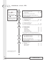
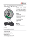
1 - programming manual
Set up
Set Down
L
Program access
Display mode
l/mn
1
4
2
Start a regeneration
In service
3
L
Time of day
Flow
Regeneration
L/mn
Sensor
Regeneration Lockout
R
Reserve
R
Total Capacity
Flow rate display
Programming Mode
R
Available volume
CaCO
1
Alkaline Battery low
Totalizer display
4
Water Hardness
2
2:00
Regeneration Time
3
Up flow brine draw &
slow rinse
Backwash
Rapid rinse
Down Flow Brine draw &
slow rinse
Brine tank refill
2
3200 ET & RM
2 - valve operation
1
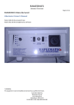
BUTTON FUNCTION
1
4
L
2
L/mn
3
1
1.1
EXTRA CYCLE BUTTON:
4
2
3
Depress this button will initiate a manual regeneration.
1. With timeclock or meter delayed regeneration, an extra regeneration will occur at the set regeneration
time. Depress this button for 5 seconds, a regeneration will force to occur immediately.
2. With meter immediate regeneration, an extra regeneration will occur immediately.
1.2
TOTALIZER/FLOW RATE BUTTON:
L
l/min
This button is only functional with meter valve.
Depressing the button once will display the flow rate (in litre/minute). Depressing the button once again
will display the total accumulation of water treated by the valve since it was last reset. Depressing the button once more will return the display to time of day or volume remaining.
Depress the button for 25 seconds will reset the totalizer display and the arrow(1) will flash to indicate to
the operator that the reset is done properly.
(1) under the pictogram
1.3
L
PROGRAM BUTTON:
The installer during the valve programming uses this button.
1.4
SET BUTTON:
This button is used to set the current time of day, adjust the parameter value during the valve programming
and the time remaining in a regeneration cycle.
1.5
BATTERY INDICATOR:
When the valve is operating on line power, this led will turn on whenever the 9V alkaline battery (not included) used for the memory backup needs to be replaced or is disconnected.
In case of a power outage, the battery will maintain the current operating displays for approximately 24
hours at the maximum battery capacity.
3
3200 ET & RM
2 - valve operation
2
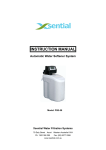
SERVICE VALVE OPERATION
2.1
METER VALVE
In service the time of day alternates being viewed with the volume remaining. The water flow through the unit is
indicated by the meter arrow(1) that flashes in a direct relationship to flow rate. The volume remaining counts down
with the consumption of treated water.
(1) under the pictogram
2.1.A
METER DELAYED REGENERATION
When the volume remaining reaches the reserve capacity (calculated by the electronic), the reserve arrow (2)
flashes as an indication. The regeneration will initiate at the pre-set regeneration time.
When the reserve capacity is exhausted, the display will show a succession of dash and the regeneration will
initiate at the pre-set regeneration time.
R
(2) under the pictogram
L/mn Sensor
R
2.1.B
L
R
METER IMMEDIATE REGENERATION
When the volume remaining reach zero, the regeneration starts immediately.
Note for 9000 and 9500 valves: in service, the time of day display will alternate with the tank in service display and the
volume remaining display of this one.
R
R
2.2
L
L/mn Sensor
TIMECLOCK VALVE
In service, the time of day is viewed all time. The valve operates normally until the pre-set number of days since
the last regeneration reaches. Once this occurs, regeneration will start immediately at the pre-set regeneration
time.
2.3
METER VALVE WITH A REGENERATION DAY OVERRIDE
When the valve has reached its set days since regeneration override value, the regeneration will initiate
immediately or delayed at the pre-set regeneration time regardless of the volume remaining.
4
3200 ET & RM
2 - valve operation
3
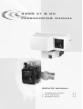
VALVE OPERATION DURING A REGENERATION
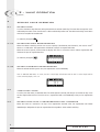
3.1
3200 ET TIMER
In regeneration, the valve displays what regeneration cycle has reached and the time remaining in that cycle. The
time remaining is in minutes and tenth of minute. Once the cycle time reaches zero, the valve drives to the next
cycle.
R
L
R
1
L/mn Sensor
R
R
The valve is advancing to cycle 1,
number 1 is flashing.
1
A diode turns on next to
corresponding pictogram.
L
L/mn Sensor
The valve is in cycle 1,
10 min is remaining in that cycle.
2
Depress the button
during a regeneration cycle will immediately advance the valve to the next cycle.
Depress the button
or
during regeneration cycle will adjust the time remaining. The regeneration cycle
programming will not be changed.
4
3
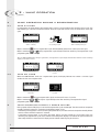
Note for 9000 and 9500 valve: during a regeneration, the regeneration cycle display will alternate with the volume remaining
display of the tank in service.
R
L/mn Sensor
R
Regeneration cycle 1
3.2
R
L
L
L/mn Sensor
R
Volume remaining of the tank
in service
3200 RM TIMER
When the 3200 RM timer sends out a regeneration signal, the display indicates the number 1 and the signal
duration for the start of regeneration.
R
L
1
4
2
3
L/mn Sensor
R
Regeneration signal is sent out,
it lasts 6 min.
1
The signal is indicated
by a diode
2
Depress the button
during the regeneration signal, the electronic returns in service.
Depress the button
or
during the signal will adjust the time remaining. The regeneration signal
programming will not be changed.
4
4
3
VALVE OPERATION DURING A POWER FAILURE
During a power failure all displays turn off and the regeneration cycles are delayed. The valve continues to operate
normally until the line power is restored or the 9V-battery power is lost.
- If the battery backup power is never lost during the power failure, the valve continues to operate normally without
the loss of data until the line power is restored.
- If the battery backup power is lost during the power failure, the valve stored the current time of day, the
remaining, the regeneration cycle status and the various diagnostic displays. To indicate this type of failure, the
time of day will flash to inform that this display and the volume remaining may be incorrect.
5
3200 ET & RM
3 - program level #1
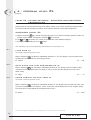
Note:
1. Push the
per display.
button once
2. Option settings may be
changed by pushing the
and
set buttons.
3. Depending on current valve
programming, some displays
will not be viewed or set.
P
P
P
P
P
P
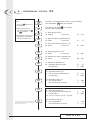
The valve is in service position. To enter in the first level, push
and hold the
button for 5 seconds.
1.1. Water Hardness in °tH (1)
Ex.: 30 °tH
[- - - - - 30]
1.2. Water Hardness after mixing valve in °tH (1)
Ex.: 6 °tH
[P - - - - -6]
1.3. System capacity in m3 °tH (1)
Ex.: 1200 m3 °tH
[ - - - 1200]
1.4. Regeneration time
Ex.: 2:00
[ - - 2:00 - ]
Regeneration cycle time setting.
1.5. Cycle #1: Backwash for ET (2), signal for RM
Ex.: for ET:
for RM:
[1--10.0]
[1---6.0]
P
1.6. Cycle #2: Brine draw/slow rinse for ET (2)
Ex.: for ET, not used for RM
[2--60.0]
P
1.7. Cycle #3: Rapid rinse (2)
Ex.: for ET, not used for RM
[3--10.0]
1.8. Cycle #4: Brine refill (2)
Ex.: for ET, not used for RM
[4--12.0]
1.9. Cycle #5
Ex.: not used
[5--OFF]
P
P
P
1.10. Cycles #6
Ex.: not used
Note: not viewed if cycle #5 is set on OFF.
P
Level #1 exit.
The valve returns in normal operation.
[6--OFF]
(1) The unit of measure depends on the display format
chosen. All examples above are based on the cubic
meter format. (see point 2.12).
(2) Only available with down flow regeneration valves.
For up flow regeneration valves, the cycles below
apply to:
- Cycle #1: Brine draw & slow rinse
- Cycle #3: Rapid rinse
- Cycle #2: Backwash
- Cycle #4: Brine refill
6
3200 ET & RM
3 - program level #1
LEVEL 1 - OPTION SETTINGS - INSTALLER PROGRAMMING
This level includes the functioning parameters of the softener related to the site conditions.
Note: If the chemical pump output feature is active, first remove the flow meter harness from the meter cover before
entering any program level.
ENTERING LEVEL #1
A - Depress the
button for 5 seconds. The program arrow turns on and the first display viewed is used to set
the inlet water hardness.
B - The
and
set buttons are used to set the parameter values of different displays.
C - Passing to the next display, push the
button.
Note: depending on the current programming, certain displays will not be viewed or set.
1.1
WATER HARDNESS
Not viewed in timeclock regeneration mode or when the volume override is activated.
The unit of measure used for the parameter is °tH (1). The red led next to the symbol identifies this parameter
CaCO3. Adjust the value with the
and
set buttons.
(1)
Ex.: Hardness 30 °tH
[- - - - - 30]
1.2
WATER HARDNESS AFTER THE MIXING VALVE (P)
Not viewed in timeclock regeneration mode, with the volume override activated, or in US format, or if 8 set on 1 (2)
Depress
button. The letter "P" identifies this parameter. The unit of measure is the °tH (1). Adjust the value
with the
and
set buttons.
Ex.: Hardness after the mixing valve 6 °tH (1) :
[P - - - - 6]
1.3
SYSTEM CAPACITY
Not viewed in timeclock regeneration mode or when the volume override is activated.
Depress the
button. The red led next to the symbol R
turns on. The unit of measure used is the m3 °tH (1).
This display uses to set the capacity of the softener. If required, the electronic will calculate a reserve. Adjust
the value with the
and
set buttons.
3
(1)
Ex.: Capacity 1200 m °tH :
[ - - - -1200]
(1) The unit of measure depends on the display format chosen. All examples above are based on the cubic meter format. (see point 2.12).
(2) see point 2.16
7
3200 ET & RM
3 - program level #1
1.4
REGENERATION TIME
Not viewed in meter immediate regeneration mode.
1
2
Depress the
button. The red led next to the symbol 4 32:00 turns on as well as a non-flashing dot between
the hour set and minute set of numbers. Set the regeneration time with the
and
set buttons.
Ex.: Regeneration at 2:00 A.M.
[--2:00--]
1.5
TO
1.10
REGENERATION CYCLE PROGRAMMING
The cycle 6 will not be viewed if the cycle 5 is cancelled [ 5 - - - O F F ] . For RM, the cycle 1 will only be viewed.
Depress the
button. The next displays are a part of a series of option settings used to program the regenerate cycles. Up to 6 cycles can be programmed. Only a led identifies the four first displays led. Each display is
used to set the duration time ( in minute) of that cycle in the regeneration.
The first display in the series is regeneration cycle 1, example: Backwash (1)
Ex.: Cycle 1 (Backwash): 8 minutes
Cycle 4 (Brine refill): 8.4 minutes (8 min and 24 s.)
[1 - - - 8.0]
[4 - - - 8.4]
EXISTING THE LEVEL 1 PROGRAMMING
When the cycle 5 display (or cycle 6 if cycle 5 is activated) is viewed, depress once again the
The electronic returns in service.
button.
Installer note:
1. Reserve capacity calculation: in meter delayed regeneration mode, the electronic automatically calculates its
reserve capacity based on daily water usage.
2. System capacity and water hardness will not be viewed or set with the timeclock systems or with the volume override
set.
3. The regeneration time will not be viewed or set with the meter immediate regeneration mode.
4. Voltage range for reliable operation of the electronic:
24V +/- 10%
Frequency: 50/60 Hz
8
3200 ET & RM
4 - program level #2
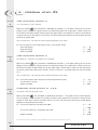
Note:
P
1. Push the
per display.
button once
1
1
2. Option settings may be
changed by pushing the
and
set buttons.
3. Depending on current valve
programming, some displays
will not be viewed or set.
4
2
3
2
Then depress the button
for 5 seconds.
You are in the second level.
4
3
P
2.1. Flow rate (Fr) in l/min (1)
Ex.: 8,6 l/min
non adjustable
[Fr - - 8.6]
P
2.2. Days since the last regeneration (d)
Ex.: 2 days
non adjustable
[d - - - -2]
P
2.3. Prior service volume used in m3 (1) (E)
Ex.: 58,6 m3
non adjustable
[E - - 58.6]
P
2.4. Reserve capacity (rc) in m3 (1)
Ex.: 24,6 m3
non adjustable
[rc - - 24.6]
P
2.5. Previous days water usage (Pd) in m3 (1)
Ex.: 28,4 m3
non adjustable
[Pd - - 28.4]
P
2.6. Indicator of chlorination (J)
Ex.: - Chloration during the cycle 2
- No chloration
[J - - - - -2]
[J - - -OFF]
2.7.a. Start time of relay #1 (y)
Ex.: - Turn on at the start of Backwash.
- Cancel setting
[y - - - - - 0]
[ - - - OFF]
2.7.b. End time of relay #1 (y)
Ex.: - Turn off after 10 min
- Turn off when back to service
[ - - - - 10.0]
[ - - - - - - S]
P
P
P
(1) The unit of measure depends on the display format
chosen. All examples above are based on the cubic
meter format. (see point 2.12).
The valve is in service position. To enter in the second level,
push and hold the
button for 5 seconds.
P
2.8.a. Start time of relay #2 (r)
Ex.: - Turn on 10 min after start Backwash
- Cancel setting
Note: setting not viewed if relay #1 is cancelled.
2.8.b. End time of relay #2 (r)
Ex.: - Turn off after 60 min
- Turn off when back to service.
[r - - - - 10]
[r - - - OFF]
[- - - - - 60]
[- - - - - - S]
9
3200 ET & RM
4 - program level #2
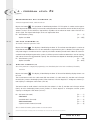
Note:
P
1. Push the
per display.
button once
2. Option settings may be
changed by pushing the
and
set buttons.
P
3. Depending on current valve
programming, some displays
will not be viewed or set.
P
P
P
2.9.a Time setting for chemical pump (n) :
Ex.: - Turn on in service for 1 min
- Cancel setting
Note: setting not viewed on timeclock valves.
[n - - - - 1.0]
[n - - - OFF]
2.9.b Volume count setting for chemical pump in m3 (1)
Ex.: - Turn on every 0,2 m3
[- - - - 0.2]
2.10. Regeneration day override (A)
Ex.: - Override every 7 days
[A - - - - 7]
- Cancel setting
[A - - OFF]
Note: in timeclock regeneration, never cancel this setting.
2.11. Volume override (b) in m3 (1)
Ex.: - Regenerate every 80 m3
[b - - - 80]
Note: if b is set, water hardness and system capacity are not viewed.
2.12. Display format (U)
Ex.: - US format (Gallon)
[U - - - - - 1]
- Litre format
[U - - - - - 2]
- Standard metric
[U - - - - - 3]
- Cubic meter format
[U - - - - - 4]
- Japanese metric format
[U - - - - - 5]
Note: If this parameter is changed, the programming comes
immediately back to the level 1 and directly followed by the level 2.
P
2.13.a ValveType (o)
Ex.: - 2510 - 3900 valves (ET timer)
- 9000 - 9500 valves (ET timer)
P
2.13.b Tank in service indicator (o-4)
Note:only viewed for 9000 and 9500,when "o" set on 4 (see 2.13.a)
Ex.: - Tank 1 in service
[o - 4 - - U1]
P
2.14 Regeneration type (7)
Ex.: - Timeclock
- Meter immediate
- Meter delayed
[o - - - - - 3]
[o - - - - - 4]
[7 - - - - - 1]
[7 - - - - - 2]
[7 - - - - - 3]
(1) The unit of measure depends on the display
format chosen. All examples above are based on
the cubic meter format. (see point 2.12).
10
3200 ET & RM
4 - program level #2
Note:
P
1. Push the
per display.
button once
2. Option settings may be
changed by pushing the
and
set buttons.
3. Depending on current valve
programming, some displays
will not be viewed or set.
P
2.15 Flow meter size (F)
Ex.: - Standard 3/8"
- Standard 3/4"
- Standard 1"
- Standard 1.5"
- Standard 2"
- Standard 3"
- Not used
[F - - - - - 0]
[F - - - - - 1]
[F - - - - - 2]
[F - - - - - 3]
[F - - - - - 4]
[F - - - - - 5]
[F - - - - - 6]
2.16 Mixing valve location (8)
Ex.: - No mixing valve
- Mixing valve before flow meter
- Mixing valve after flow meter
[8 - - - - - 1]
[8 - - - - - 2]
[8 - - - - - 3]
2.17 System type (9)
Ex.: - System #4 - One single electronic
or 9000 or 9500 valves
- System #5 - "Interlock": Multivalves system
with independent ET valves
[9 - - - - - 5]
P
2.18 Program lockout (Pl)
Ex.: - Cancel lockout
- Lockout active
[Pl - - - OFF]
[Pl - - - - On]
P
Level #2 exit.
The valve returns in normal operation.
P
[9 - - - - - 4]
(1) The unit of measure depends on the display
format chosen. All examples above are based on
the cubic meter format. (see point 2.12).
11
3200 ET & RM
4 - program level #2
LEVEL #2 - OPTION SETTINGS - SOFTENER MANUFACTURER
PROGRAMMING
Setting up the valve during manufacturing of the softener requires access to the second level of programming.
This level includes the functioning parameters of the softener related to actual system configuration.
ENTERING LEVEL #2
A- Depress the button
for 5 seconds. The program arrow turns on and the first display viewed is used to set
the inlet water hardness. Then depress the button
for 5 seconds.
B- The
and
set buttons are used to set the parameter values of different displays.
C- Passing to the next display, push the
button.
1
4
2
3
Note: depending on the current programming, certain displays will not be viewed or set.
2.1
FLOW RATE (Fr)
Not viewed in timeclock regeneration mode.
Depress the button
. This display is identified by the letters "Fr". This first display is the current flow rate of
treated water. The unit of measure is the litre per minute.
Ex.: 8,6 l/min
[Fr - - - 8.6]
2.2
DAYS SINCE THE LAST REGENERATION (d)
Depress the button
. This parameter is identified by the letter "d". This display shows the number of days
recorded since the last regeneration. This display is used as an aid in the valve maintenance and is not an
option setting.
Ex.: 2 days
[d - - - - - 2]
2.3
PRIOR SERVICE VOLUME USED (E)
Not viewed in timeclock regeneration mode.
Depress the button
. This display is identified by the letter "E". This display shows the amount of water used
since the last regeneration. This display is used as an aid in the valve maintenance and is not an option setting.
The unit of measure used depends on the display format chosen (1).
Ex.: 58,6 m3 (1)
[E - - - 58.6]
(1) The unit of measure depends on the display format chosen. All examples above are based on the cubic meter format. (see point 2.12).
12
3200 ET & RM
4 - program level #2
2.4
RESERVE CAPACITY (rc)
Not viewed in timeclock regeneration mode.
Depress the button
. This parameter is identified by the letters "rc". This display shows the reserve capacity
calculated by the electronic for the present day. This display is used as an aid in the valve maintenance and is not
an option setting. The unit of measure used depends on the display format chosen (1).
Ex.: 24,6 m3 (1)
[rc - - 24.6]
2.5
PREVIOUS DAYS WATER USAGE (Pd)
Not viewed in timeclock regeneration mode.
Depress the button
. This display is identified by the letters "Pd". This display shows the previous days water
usage recorded. This display is used as an aid in the valve maintenance and is not an option setting. The unit
of measure used depends on the display format chosen (1).
Ex.: 28,4 m3 (1)
[Pd - - 28.4]
2.6
LOCATION FOR CHLORINATION INDICATOR (J)
Not viewed in RM version (Remote Meter).
Depress the button
. This display is identified by the letter "J". This display is used to set the desired regeneration cycle number where the chlorinating indicator will turn on in the regeneration display. This parameter does
not command the chlorinator whom has to be handled by a microswitch or by a time auxiliary output.
Ex.: No chlorinator installed
[J- - - OFF]
Chlorinator to turn on during the cycle 2
[J- - - - - -2]
Note: During a regeneration with the chlorinating indicator set, for example cycle 2,
the regeneration display will show:
[2C- - 38.2]
Timed auxiliary output programming (y) (r) (n):
See points 2.7, 2.8 and 2.9
Depress the button
. The next three display viewed are part of a series of option setting used to program the
auxiliary relay output. The first two settings ("y" and "r") turn the output on / off during regeneration only.
Two independent signals can be programmed for the same output during regeneration. The third ("n") turns the output on
during the service only, when a set volume of water used has accumulated and for a set duration.
Note: when more than one of these settings are used, it will be up to the softener manufacturer to supply the
switching logic necessary to operate two or three of device of equipment at a time from a single relay output.
(1) The unit of measure depends on the display format chosen. All examples above are based on the cubic meter format. (see point 2.12).
13
3200 ET & RM
4 - program level #2
2.7.A
&
2.7.B
TIME AUXILIARY OUTPUT (Y)
2.7.B only viewed if 2.7.A (y) is activated.
Depress the button
. This parameter is identified by the letter "y". This option setting consists of two
displays. The first display is used to set the turn on time of the output. The second one is used to set the turn
off on time of the output. An OFF setting cancels this option. With a set off time of "S" will turn the output off
at the back of service. All settings are in minutes. The setting time of the output has not to be longer than the
total time of regeneration.
Note: all setting times of the output are synchronised with regeneration cycle timing.
Ex.: Turn on output at start of regeneration cycle 1, turn off after 10 min
- Start time display
- Stop time display
- Option cancelled
2.8.a
&
2.8.b
[y - - - - - 0]
[ - - - - 10.0]
[y - - - OFF]
TIME AUXILIARY OUTPUT (r)
Not viewed if [y - - OFF]; 2.8.b only viewed if 2.8.a is activated.
Depress the button
. This parameter is identified by the letter "r". This option setting consists of two
displays. The first display is used to set the turn on time of the output. The second one is used to set the turn
off time of the output. An OFF setting cancels this option. With a set off time of "S" will turn the output off at
the start of service. All settings are in minutes. The turn on time of "r" cannot be lower than the turn off time
of "y".
Note: all setting times of the output are synchronised with regeneration cycle timing.
Ex.: - Turn on the output 15 min after the start of the regeneration cycle 1
- Turn off when in service
- Option cancelled
2.9.a
&
2.9.b
[r - - - - 15]
[- - - - - -S]
[r- - - OFF]
CHEMICAL PUMP OUTPUT (n) - T.A.O.
Not viewed in timeclock regeneration mode.
Depress the button
. This parameter is identified by the letter "n". This option consists of two displays.
This first display is used to set the turn on time (in minutes) of the output. This second one is used to set the
volume of water flow at which the output will turn on. The unit of measure used in the second display
depends on the display format chosen (1).
Ex.: - Turn on the output for 1min after every 200 l (1)
[n - - - - 1.0]
[ - - - - 200]
(1)
- Turn on the output for 1 second after every 50 l
[n - - - - - P]
[- - - - - -50]
- Option cancelled
[n - - - OFF]
(1) The unit of measure depends on the display format chosen. All examples above are based on the cubic meter format. (see point 2.12).
14
3200 ET & RM
4 - program level #2
2.10
REGENERATION DAY OVERRIDE (A)
In timeclock regeneration mode, a value must be set.
Depress the button
. This parameter is identified by the letter "A". This option is used to set the regeneration day override option setting. This override setting determines the maximum amount of time (in days) the
softener can be in service without a regeneration, regardless of the volume of water used or the lack of a
sensor signal. The regeneration begins at the set regeneration time.
Ex.: - Override every 7 days
[A - - - - - 7]
- Option cancelled
[A - - - OFF]
2.11
VOLUME OVERRIDE (b)
Not viewed in timeclock regeneration mode.
Depress the button
. This display is identified by the letter "b". The volume override option is used to set
the maximum amount of water that can be used before a regeneration cycle is called for. This option is typically used to bypass standard reserve or capacity calculations made by the electronic. When this feature is
used with meter delayed regeneration systems, it will be up to the installer to determine a reserve capacity
and subtract it from the calculated full capacity. The unit of measure depends on the display format chosen (1).
Ex.: - Override every 2.6 m3 (1)
- Option cancelled
2.12
[b- - - - 2.6]
[b- - - OFF]
DISPLAY FORMAT (U)
Note: If this parameter is changed, the programming comes immediately back to the level 1 and directly followed by
the level 2.
Depress the button
. This display is identified by the letter "U". One of five following display formats can
be used.
The current format used is the cubic meter (U4): the volume is in cubic meter (m3), the flow rate in litre per
minute (l/min), 24 hours timekeeping format, water hardness in French degrees or °tH degrees and the system capacity in °tH degrees cubic meter (°tH x m3).
The format used for small volume is the litre (U2): the volume is in litre (l), the flow rate in litre per minute
(l/min), 24 hours timekeeping format, water hardness in French degrees or °tH degrees and the system
capacity in °tH degrees cubic meter (°tH x m3).
Ex.: - US format (not used)
- Litre format
- Standard metric (not used)
- Cubic meter format
- Japanese metric format (not used)
[U - - - - - 1]
[U - - - - - 2]
[U - - - - - 3]
[U - - - - - 4]
[U - - - - - 5]
Note: for further information, please contact our customer service.
(1) The unit of measure depends on the display format chosen. All examples above are based on the cubic meter format. (see point 2.12).
15
3200 ET & RM
4 - program level #2
2.13.A
VALVE TYPE (O)
Not viewed in RM version (Remote Meter)
Depress the button
. This parameter is identified by the letter "o". This display is used to set the type of
valve used with the 3200 ET. There are five possible settings, only the numbers 3 and 4 are used.
Not used
[o - - - - - 1]
Not used
[o - - - - - 2]
2510 - 3900 valves. When the number 3 is selected, the 3200 ET timer operate normally, all led are used. The
volume remaining will be able to count down when the valve is back in service.
For 2510 / 2750 / 2850 / 2900 / 2930 / 3130 / 3150 / 3900 valves
[o - - - - - 3]
9000 and 9500 valves. When the number 4 is selected, the 3200 ET timer operate normally, all led are used.
The volume remaining will be able to count down at the start of the regeneration. During regeneration, the
volume remaining and the regeneration displays will alternate being viewed: 10 seconds for the regeneration display and 5 seconds for the volume remaining display.
For 9000/9500 valves
[o - - - - - 4]
TANK IN SERVICE (O-4)
2.13.B
Only visible with [ o - - - 4 ] : , for 9000 and 9500 valves
Depress the button
. This display is identified by "o-4". This display shows which tank (Unit) is in service (adjusted by the installer).
Ex.: - tank 1 in service
[o - 4- - - U1]
REGENERATION TYPE (7)
2.14
Depress the button
. This display is identified by the number "7". This option is used to set the regeneration type. There are several possible option settings:
- Timeclock: the electronic determines that regeneration is required when the set regeneration time has
been reached. The regeneration day override setting (see point 2.10) determines the number of days
between two regenerations.
[7 - - - - - 1]
- Meter immediate: the electronic determines that regeneration is required when the available volume of
softened water drops to zero. The regeneration begins immediately.
[7 - - - - - 2]
- Meter delayed: the electronic determines that regeneration is required when the available
volume of softened water drops to the reserve capacity. The regeneration begins immediately
at the set regeneration time only when the service flow has not been detected. With service
flow, the regeneration will be delayed in two 10 minute sections. After then if there is always
a flow, the regeneration begins immediately. There will be not a delay if the reserve capacity
is zero.
[7 - - - - - 3]
- Regeneration type 4: not used
[7 - - - - - 4]
Note: for the following options, please contact our customer service.
- Sensor immediate regeneration
- Sensor delayed regeneration
[7 - - - - - 5]
[7 - - - - - 6]
16
3200 ET & RM
4 - program level #2
2.15
FLOW METER SIZE (F)
Not viewed in timeclock regeneration mode.
Depress the button
. This parameter is identified by the letter "F". This option is used to set the flow
meter size. Seven settings are possible.
Standard 3/8"
[F - - - - - 0]
Standard 3/4"
[F - - - - - 1]
Standard 1"
[F - - - - - 2]
Standard 1.5"
[F - - - - - 3]
Standard 2"
[F - - - - - 4]
Standard 3"
[F - - - - - 5]
Not used
[F - - - - - 6]
2.16
MIXING VALVE LOCATION (8)
Not viewed in timeclock regeneration mode.
Depress the button
. This display is identified by the number "8". This option is used to indicate where
the mixing valve is located. Three settings are possible.
No mixing valve
[8 - - - - - 1]
Mixing valve before flow meter
[8 - - - - - 2]
Mixing valve after flow meter
[8 - - - - - 3]
2.17
SYSTEM TYPE (9)
Not viewed in RM version (Remote meter).
Depress the button
. This display is identified by the number "9". This display is used to set the type of
system the valve is operating in. Two settings are available.
Single valves and 9000/9500: System #4.
[9 - - - - - 4]
Two valves interlocked regeneration: System #5. Each 3200 ET timer generates a lockout signal whenever it
is in regeneration. The other 3200 ET timer will delay the start of regeneration until the lockout signal is
removed.
Indication on each 3200 ET timer
[9 - - - - - 5]
(1) The unit of measure depends on the display format chosen. All examples above are based on the cubic meter format. (see point 2.12).
17
3200 ET & RM
4 - program level #2
2.18
PROGRAM LOCKOUT (Pl)
Depress the button
. This display is identified by the letters "Pl". This display is used to prevent certain
programming displays from being viewed or set. Two settings are available:
Protection cancelled
[Pl - - - OFF]
Protection active
[Pl - - - - On]
Settings and displays able to be viewed or reset
with protection active
In service:
- Time of day
- Volume remaining
- Flow rate
- Totalizer
In programming level 1
- Water hardness
- Water hardness after mixing valve (P)
- regeneration time
In programming level 2
- Flow rate (Fr)
- Days since the last regeneration (d)
- Prior service volume used (E)
- Reserve capacity (rc)
- Previous days water usage (Pd)
The program lockout can be cancelled by depressing the button
for 25 seconds.
ATTENTION: depress the button
for 25 seconds when the program lockout is not activated will erase all
previous display setting; the electronic will reset to default values. The electronic programming will have to
be completely redone.
EXITING THE LEVEL 2 PROGRAMMING
Depress again the button
, the electronic comes back in service.
Note: for further information, please contact our customer service.
18
3200 ET & RM
Reproduction forbidden 09/02 - P/N 27231
GB