1
PROCESS ANALYSERS
SERVOPRO 4000 Series
Analyser
Installation Manual
Part Number:
Revision:
Language:
04000005C
7
UK English
This page intentionally blank
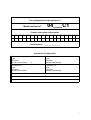
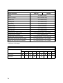
The configuration of this analyser is
04___C1
:
Model and Issue
Feature and option code number
F1 F2 F3 F4 F5 F6 F7 F8 F9 F10 F11 F12 F13 F14 F15 F16 F17 F18
__ _ _
_
_
_
_
_
_
Serial number
_
_
_
_
_
_
_
_
_
_
_____
Instrument Configuration
Transducer I1
Type:
Serial No:
Sample Inlet Position
1
Transducer I3
Type:
Serial No:
Sample Inlet Position
Transducer I2
Type:
Serial No:
Sample Inlet Position
Transducer I4
Type:
Serial No:
Sample Inlet Position
Servomex Order Reference No:
Software Revision No:
Completed By:
Date :
i
WARNINGS, CAUTIONS AND NOTES
This publication includes WARNINGS, CAUTIONS AND NOTES which provide
information relating to the following:
WARNINGS :
Hazards which could result in personal injury or death.
CAUTIONS :
Hazards which could result in equipment or property
damage.
NOTES :
Alert the user to pertinent facts and conditions.
NOTE
This manual covers installation, routine maintenance and fault diagnosis on all the
4000 series 'C' models.
The following symbols are used on the rear of the analyser:
Earth (ground) terminal
Caution, refer to operator manual
ii
List of Contents
SECTION 1 INTRODUCTION . . . . . . . . . . . . . . . . . . . . . . . . . . . . . . . . . . . . . . . . . 1.1
1.1
Introduction . . . . . . . . . . . . . . . . . . . . . . . . . . . . . . . . . . . . . . . . . . . . . . . . . . . 1.1
1.2
General description . . . . . . . . . . . . . . . . . . . . . . . . . . . . . . . . . . . . . . . . . . . . . 1.1
1.3
Location of components . . . . . . . . . . . . . . . . . . . . . . . . . . . . . . . . . . . . . . . . . . 1.3
1.4
Transducer site numbering system . . . . . . . . . . . . . . . . . . . . . . . . . . . . . . . . . 1.4
1.5
Output numbering system . . . . . . . . . . . . . . . . . . . . . . . . . . . . . . . . . . . . . . . . 1.4
1.6
Transducer full scale deflection . . . . . . . . . . . . . . . . . . . . . . . . . . . . . . . . . . . . 1.4
1.7
Conversion of transducer measuring units . . . . . . . . . . . . . . . . . . . . . . . . . . . . 1.5
1.8
Calibration - General . . . . . . . . . . . . . . . . . . . . . . . . . . . . . . . . . . . . . . . . . . . . 1.7
1.9
Automatic calibration options . . . . . . . . . . . . . . . . . . . . . . . . . . . . . . . . . . . . . . 1.7
SECTION 2 INSTALLATION - GENERAL . . . . . . . . . . . . . . . . . . . . . . . . . . . . . . . 2.1
2.1
Introduction . . . . . . . . . . . . . . . . . . . . . . . . . . . . . . . . . . . . . . . . . . . . . . . . . . . 2.1
2.2
Unpacking and inspection . . . . . . . . . . . . . . . . . . . . . . . . . . . . . . . . . . . . . . . . 2.2
2.3
Bench mount installation . . . . . . . . . . . . . . . . . . . . . . . . . . . . . . . . . . . . . . . . . 2.3
2.4
Panel mount installation . . . . . . . . . . . . . . . . . . . . . . . . . . . . . . . . . . . . . . . . . . 2.3
2.5
Rack slide mounting installation . . . . . . . . . . . . . . . . . . . . . . . . . . . . . . . . . . . . 2.4
SECTION 3 INSTALLATION - ELECTRICAL . . . . . . . . . . . . . . . . . . . . . . . . . . . . 3.1
3.1
Electrical power connection . . . . . . . . . . . . . . . . . . . . . . . . . . . . . . . . . . . . . . . 3.1
3.2
Signal connections . . . . . . . . . . . . . . . . . . . . . . . . . . . . . . . . . . . . . . . . . . . . . . 3.2
3.2.1
mA output and relay output connections . . . . . . . . . . . . . . . . . . . . . 3.4
3.2.2.
Analogue inputs . . . . . . . . . . . . . . . . . . . . . . . . . . . . . . . . . . . . . . . . 3.6
3.2.3.
External autocalibration connection . . . . . . . . . . . . . . . . . . . . . . . . 3.7
3.3
Serial data/Modbus connection . . . . . . . . . . . . . . . . . . . . . . . . . . . . . . . . . . . . 3.8
3.4
Continuous mode . . . . . . . . . . . . . . . . . . . . . . . . . . . . . . . . . . . . . . . . . . . . . . . 3.9
3.5
Modbus mode . . . . . . . . . . . . . . . . . . . . . . . . . . . . . . . . . . . . . . . . . . . . . . . . 3.10
3.6
EMC Installation . . . . . . . . . . . . . . . . . . . . . . . . . . . . . . . . . . . . . . . . . . . . . . . 3.11
SECTION 4 INSTALLATION – GAS CONNECTIONS . . . . . . . . . . . . . . . . . . . . . 4.1
4.1
Introduction . . . . . . . . . . . . . . . . . . . . . . . . . . . . . . . . . . . . . . . . . . . . . . . . . . . 4.1
4.2
Calibration gases . . . . . . . . . . . . . . . . . . . . . . . . . . . . . . . . . . . . . . . . . . . . . . . 4.1
4.2.1
Gfx transducer low and high calibration . . . . . . . . . . . . . . . . . . . . . 4.2
4.2.2
IR transducer low and high calibration . . . . . . . . . . . . . . . . . . . . . . 4.2
4.2.3
Paramagnetic transducer low and high calibration . . . . . . . . . . . . . 4.2
4.2.4
Zirconia transducer low and high calibration . . . . . . . . . . . . . . . . . . 4.3
4.3
Gas connections . . . . . . . . . . . . . . . . . . . . . . . . . . . . . . . . . . . . . . . . . . . . . . . 4.3
4.4
Reading flowmeters . . . . . . . . . . . . . . . . . . . . . . . . . . . . . . . . . . . . . . . . . . . . . 4.5
4.5
Autocalibration overview . . . . . . . . . . . . . . . . . . . . . . . . . . . . . . . . . . . . . . . . . 4.5
4.6
Autocalibration valve installation . . . . . . . . . . . . . . . . . . . . . . . . . . . . . . . . . . . 4.7
4.7
Power up . . . . . . . . . . . . . . . . . . . . . . . . . . . . . . . . . . . . . . . . . . . . . . . . . . . . 4.10
SECTION 5 ROUTINE MAINTENANCE . . . . . . . . . . . . . . . . . . . . . . . . . . . . . . . . 5.1
5.1
Replacing fan filter element . . . . . . . . . . . . . . . . . . . . . . . . . . . . . . . . . . . . . . . 5.1
5.2
Replacing the sample filter element . . . . . . . . . . . . . . . . . . . . . . . . . . . . . . . . . 5.1
5.3
Cleaning . . . . . . . . . . . . . . . . . . . . . . . . . . . . . . . . . . . . . . . . . . . . . . . . . . . . . . 5.2
5.4
Toxic/flammable samples - routine leak test . . . . . . . . . . . . . . . . . . . . . . . . . . 5.2
iii
SECTION 6
SPARES . . . . . . . . . . . . . . . . . . . . . . . . . . . . . . . . . . . . . . . . . . . . . . . 6.1
SECTION 7 TECHNICAL SPECIFICATIONS . . . . . . . . . . . . . . . . . . . . . . . . . . . . 7.1
7.1
Introduction . . . . . . . . . . . . . . . . . . . . . . . . . . . . . . . . . . . . . . . . . . . . . . . . . . . 7.1
7.2
Generic 4000 series analyser performance . . . . . . . . . . . . . . . . . . . . . . . . . . . 7.1
7.2.1
Environmental specifications . . . . . . . . . . . . . . . . . . . . . . . . . . . . . . 7.1
7.2.2
Power supply . . . . . . . . . . . . . . . . . . . . . . . . . . . . . . . . . . . . . . . . . . 7.1
7.2.3
Design standards . . . . . . . . . . . . . . . . . . . . . . . . . . . . . . . . . . . . . . 7.1
7.2.4
Analogue outputs . . . . . . . . . . . . . . . . . . . . . . . . . . . . . . . . . . . . . . 7.2
7.2.5
Alarms . . . . . . . . . . . . . . . . . . . . . . . . . . . . . . . . . . . . . . . . . . . . . . . 7.2
7.2.6
Serial data/Modbus connection . . . . . . . . . . . . . . . . . . . . . . . . . . . . 7.2
7.2.7
Analogue inputs . . . . . . . . . . . . . . . . . . . . . . . . . . . . . . . . . . . . . . . . 7.2
7.2.8
Digital inputs . . . . . . . . . . . . . . . . . . . . . . . . . . . . . . . . . . . . . . . . . . 7.2
7.2.9
Sample wetted materials . . . . . . . . . . . . . . . . . . . . . . . . . . . . . . . . . 7.3
7.3
4100C analyser performance . . . . . . . . . . . . . . . . . . . . . . . . . . . . . . . . . . . . . . 7.5
7.4
4200C analyser performance . . . . . . . . . . . . . . . . . . . . . . . . . . . . . . . . . . . . . . 7.9
7.5
4210C analyser performance . . . . . . . . . . . . . . . . . . . . . . . . . . . . . . . . . . . . . 7.12
7.6
4900C analyser performance . . . . . . . . . . . . . . . . . . . . . . . . . . . . . . . . . . . . . 7.15
APPENDIX A EFFECTS OF VARIATIONS IN SAMPLE
COMPOSITION . . . . . . . . . . . . . . . . . . . . . . . . . . . . . . . . . . . . . . . . . A.1
APPENDIX B MODBUS PROFILE . . . . . . . . . . . . . . . . . . . . . . . . . . . . . . . . . . . . . B.1
List of Figures
Figure 1.1:
Figure 2.1:
Figure 2.2:
Figure 3.1:
Figure 3.2:
Figure 3.3:
Figure 4.1:
Figure 4.2:
Figure 4.3:
Figure 4.4:
iv
Key features of 4000 series analyser . . . . . . . . . . . . . . . . . . . . . . . . . . 1.3
Panel mounting detail. . . . . . . . . . . . . . . . . . . . . . . . . . . . . . . . . . . . . . 2.3
Rack installation exploded view . . . . . . . . . . . . . . . . . . . . . . . . . . . . . . 2.4
Position of F2 in voltage selector for 220V to 240V operation . . . . . . . 3.2
Position of F2 in voltage selector for 110V to 120V operation . . . . . . . 3.2
Signal socket assembly . . . . . . . . . . . . . . . . . . . . . . . . . . . . . . . . . . . . 3.3
Sample gland plate without autocalibration . . . . . . . . . . . . . . . . . . . . . 4.3
Sample gland plate with internal autocalibration . . . . . . . . . . . . . . . . . 4.3
External autocalibration - parallel systems . . . . . . . . . . . . . . . . . . . . . . 4.8
External autocalibration - stream systems . . . . . . . . . . . . . . . . . . . . . . 4.9
List of Tables
Table 1.1:
Table 1.2:
Table 3.1:
Table 3.2:
Table 3.3:
Table 3.4:
Table 3.5:
Table 3.6:
Table 3.7:
Table 4.1:
Table 4.2:
Table 4.3:
Table 4.4:
Table 7.1:
Table 7.2:
Table 7.3:
Table 7.4:
Table 7.5:
Table 7.6:
Table 7.7:
Table 7.8:
Table 7.9:
Table 7.10:
Table 7.11:
Table 7.12:
Table 7.13:
Table 7.14:
Table 7.15:
Table 7.16:
Table 7.17:
Table 7.18A:
Table 7.19A:
Table 7.18B:
Table 7.19B:
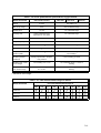
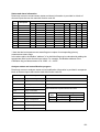
Transducer FSD values and availability in product range . . . . . . . . . . 1.6
Recommended calibration periods . . . . . . . . . . . . . . . . . . . . . . . . . . . . 1.7
Signal terminal location PL1 to PL4 . . . . . . . . . . . . . . . . . . . . . . . . . . . 3.5
Optional external autocalibration connections PL8 . . . . . . . . . . . . . . . 3.5
Signal terminal location PL5 . . . . . . . . . . . . . . . . . . . . . . . . . . . . . . . . . 3.7
External autocalibration truth table . . . . . . . . . . . . . . . . . . . . . . . . . . . . 3.8
Serial output connections PL6 . . . . . . . . . . . . . . . . . . . . . . . . . . . . . . . 3.8
Serial output data frame, start and end sequences . . . . . . . . . . . . . . . 3.9
Serial output data frame, measurement sequences . . . . . . . . . . . . . 3.10
4900C calibration gas examples . . . . . . . . . . . . . . . . . . . . . . . . . . . . . 4.2
4100C and 4200C sample port vs transducer type . . . . . . . . . . . . . . . 4.4
4210C sample port type . . . . . . . . . . . . . . . . . . . . . . . . . . . . . . . . . . . . 4.4
4900C sample port type . . . . . . . . . . . . . . . . . . . . . . . . . . . . . . . . . . . . 4.5
Sample wetted materials . . . . . . . . . . . . . . . . . . . . . . . . . . . . . . . . . . . 7.3
Sample wetted materials, continued . . . . . . . . . . . . . . . . . . . . . . . . . . 7.4
4100C performance specification, oxygen . . . . . . . . . . . . . . . . . . . . . . 7.6
4100C performance specification, Gfx . . . . . . . . . . . . . . . . . . . . . . . . . 7.7
Gfx trace measurement cross sensitivity information . . . . . . . . . . . . . . 7.7
4100C performance specification, IR . . . . . . . . . . . . . . . . . . . . . . . . . . 7.8
152X measurement ranges in 4100C . . . . . . . . . . . . . . . . . . . . . . . . . 7.8
4200C performance specification, oxygen and IR . . . . . . . . . . . . . . . 7.10
152X measurement ranges in 4200C . . . . . . . . . . . . . . . . . . . . . . . . 7.10
4200C performance specification, Gfx . . . . . . . . . . . . . . . . . . . . . . . . 7.11
Gfx trace measurement cross sensitivity information . . . . . . . . . . . . . 7.11
4210C performance specification, oxygen and IR . . . . . . . . . . . . . . . 7.13
152X measurement ranges in 4210C . . . . . . . . . . . . . . . . . . . . . . . . 7.13
4210C performance specification, Gfx . . . . . . . . . . . . . . . . . . . . . . . . 7.14
Gfx trace measurement cross sensitivity information . . . . . . . . . . . . . 7.14
4900C performance specification, oxygen and IR . . . . . . . . . . . . . . . 7.16
152X measurement ranges in 4900C . . . . . . . . . . . . . . . . . . . . . . . . 7.16
4900C performance specification, Gfx . . . . . . . . . . . . . . . . . . . . . . . . 7.17
4900C measurement cross sensitivity information . . . . . . . . . . . . . . . 7.17
4900C performance specification, Gfx . . . . . . . . . . . . . . . . . . . . . . . . 7.18
4900C measurement cross sensitivity information . . . . . . . . . . . . . . . 7.18
v
vi
SECTION 1 INTRODUCTION
1.1
Introduction
This manual contains information regarding installation and hardware configuration of the
Servomex 4000 series analysers.
A separate Quickstart manual is also supplied with the analyser, reference part number
04000/003C. This details software configuration and operation of the analyser. Extra copies
may be ordered from Servomex.
Details of the hardware and instructions for servicing, by qualified personnel only, are
presented in the 4000 Series Service Manual. This may be ordered from Servomex using part
number 4000002C.
Technical assistance and spare parts are available from Servomex outlets (or their local
agents) listed on the back cover.
WARNING
The analyser contains no user serviceable parts inside. The instrument enclosure
protects the user from electric shock and other hazards. All servicing should be
referred to qualified personnel.
ModbusTM is a trademark of AEG-MODICON.
1.2
General description
The Servomex 4000 series analyser is a chassis into which up to four gas sensor modules may
be fitted. The chassis provides power, gas connections and other support functions to the
sensors and calculates associated sample gas concentrations. These concentrations are then
displayed on the analyser display screen and may be directed to the analogue outputs and/or
the serial output.
The analyser also supports two external analogue input signals. The data from the external
inputs may be displayed on the screen, output to the analogue outputs and/or the serial output
or accessed using Modbus.
Designed for use in modern industrial and laboratory environments, the analyser is controlled
using an integral microprocessor which provides significant user flexibility.
The 4100 analyser is designed to meet the control and product quality monitoring requirements
of industrial gas producers and users. It can monitor up to four gas streams simultaneously with
independent autocalibration for each stream (provided sufficient extra relays are installed).
The 4200 analyser is intended for monitoring flammable samples, but not those containing
hydrogen or acetylene for which the 4210 must be used. Again, up to four gas streams may be
monitored simultaneously and independent autocalibration can be used with each stream. The
zirconia transducer is not available for these analysers.
The 4900 analyser is a continuous emissions monitoring (CEMs) analyser with a maximum of
four transducers with either one or two sample streams. Independent autocalibration is
available for each stream or transducer (refer to Section 4.6).
None of the above are suitable for use with corrosive samples.
1.1
A number of optional features are available for the 4000 series. These may include the
following, depending upon analyser configuration:
•
Flow meters and needle valves (on the 4900C only) to monitor and control
sample gas flow through the instrument.
•
A sample filter to protect the gas sensor modules from particulate
contamination.
•
A sample flow alarm to monitor the sample flow and alarm when the flow falls
below a defined level. This is only available on 4100C (Gfx flow driven) and
4900C product.
•
An autocalibration manifold (for a single sample stream) to allow the instrument
to be calibrated without user intervention. On the 4100C this is only suitable for
paramagnetic transducers.
•
Additional relay output contacts to allow autocalibration of the analyser via
externally located valves.
•
Additional signal output cards to extend the number of analogue outputs and
relay outputs available to the user.
(Full technical specifications for 4000 series is presented at the back of this manual).
Start up and commissioning of the analyser should be performed as follows:
Use this manual for:
Installation
To take commissioning to the point where the analyser is
powered and operational. The installer is advised to read this
manual completely before commencing installation.
Use the Quickstart manual for:
1.2
Configuration
How to set up the clock, passwords, alarm levels, analogue
outputs, relays and other parameters.
Calibration
How to use the manual and automatic calibration/checking
facilities.
Review
How to display analogue output settings, relay allocation,
alarms, faults and analyser identity without changing the
analyser settings.
1.3
Location of components
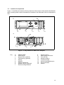
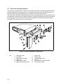
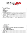
Figure 1.1 identifies the location of the key features of the analyser. Note that the identification
label (including serial number information) is located on the underside of the unit towards the
rear.
Figure 1.1: Key features of 4000 series analyser
Key
A
B
1
2
3
4
5
6
7
FRONT VIEW
REAR VIEW
Sample filter (optional)
Flowmeter(s) (optional)
Display
Keypad
Display adjustment
Needle valve(s) (optional)
Rack mounting brackets
8
9
10
11
12
13
14
15
Sample inlet(s)
Mains power connector
Fan and filter
Sample outlet(s)
Functional earth
Serial output/Modbus port
Signal terminals
Screen
1.3
1.4
Transducer site numbering system
The four internal transducers are assigned site locations represented as I1, I2, I3 and I4 on the
display.
In the case of the 4100 and the 4200 analysers, each transducer is served by a discrete sample
inlet and outlet connection on the rear panel.
In the case of the 4900 analyser, either one or two sample streams may be specified consequently only inlets/outlets numbered 1 and 2 will be used.
1.5
Output numbering system
Identification numbers appear on the rear label to identify the terminals where each output
appears and on the display when the outputs are being configured. These have a two digit
identification number of the following format : Card number. Output No.
e.g.. the outputs fitted as standard on the SIB pcb in card position 1 are:
1.6
1.1
Analogue output
1.2
Analogue output
1.3
Relay
1.4
Relay
1.5
Relay
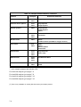
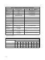
Transducer full scale deflection
The transducer full scale deflection (FSD) is the maximum concentration level that may be
measured and displayed with the precision and accuracy specified for that transducer. This
may also be termed the measurement range for the transducer. Concentration levels that
exceed 120% of the FSD are considered as over range and are indicated by the word 'OVER'
on the analyser display.
There are two set up parameters on the analyser that are expressed in terms of the FSD:
•
Calibration tolerances for the transducers.
•
Alarm hysteresis.
When defining minimum output ranges, the relevant transducer noise specification should be
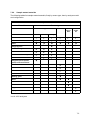
considered; refer to Section 7. (Table 1.1 lists all available transducer types and FSD values).
1.4
NOTE
The following abbreviations are used throughout this manual:
1.7
Gfx
Gas filter correlation infra-red transducer
IR
Pulsed infra-red transducer
Pm
Paramagnetic transducer
Zr
Zirconia transducer
Conversion of transducer measuring units
As supplied, the standard transducers within the analyser will measure in the units indicated in
Table 1.1. It is possible to change these units by the use of a linear scale factor (refer to
Quickstart manual). The user should note that the 4000 series software prime measurement
is in percentage, therefore trace level 'vpm' (volume parts per million) measurements already
have a scale factor of 10,000 entered as a default.
Example:
to convert vpm SO2 to mg/m3, a multiplier of 2.86 is used. As the software
actually converts from percentage levels, the overall scale factor entered as part
of the analyser configuration will be 28600.
1.5
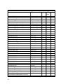
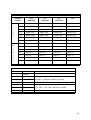
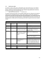
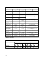
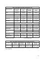
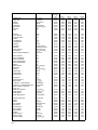
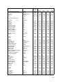
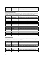
Table 1.1: Transducer FSD values and availability in product range:
Transducer
FSD
4100
4200
4900
4210
Gfx1210 CO Standard sensitivity
3000vpm CO
-
-
9
Gfx1210 CO High sensitivity
500vpm CO
9
9
9
Gfx 1210 SO2 Standard sensitivity
2500vpm SO2
-
-
9
Gfx 1210 SO2 High sensitivity
1000vpm SO2
-
-
9
Gfx 1210 NO High sensitivity
1000vpm NO
-
-
9
Gfx1210 CO2 High sensitivity
100vpm CO2
9
9
-
Gfx 1210 CH4 High sensitivity
500vpm CH4
9
9
9
Gfx 1210 N2O High sensitivity
500vpm N2O
9
9
9
IR 1520 100% CO2
100% CO2
9
9
9
IR 1520 50% CO2
50% CO2
9
9
9
IR 1520 25% CO2
25% CO2
9
9
9
IR 1520 10% CO2
10% CO2
9
9
9
IR 1520 5% CO2
5% CO2
9
9
9
IR 1520 2.5% CO2
2.5% CO2
9
9
9
IR 1520 1% CO2
1% CO2
9
9
9
IR 1520 0.5% CO2
0.5% CO2
9
9
9
IR 1520 0.25% CO2
0.25% CO2
9
9
9
IR 1521 100% CH4
100% CH4
-
9
-
IR 1521 50% CH4
50% CH4
-
9
-
IR 1521 25% CH4
25% CH4
-
9
-
IR 1521 5% CH4
5% CH4
-
9
-
IR 1522 50% CO
50% CO
-
9
-
IR 1522 25% CO
25% CO
-
9
-
IR 1522 10% CO
10% CO
9
9
9
IR 1522 2.5% CO
2.5% CO
9
9
9
IR 1522 1% CO
1% CO
9
9
9
Pm 1158 O2 Control
100% O2
9
9
9
Pm 1111 O2 Basic
100% O2
9
-
9
Pm Purity O2 (04100995A)
100% O2
9
-
-
Zirconia 704 O2 Trace
plus indicative reading above 21% O2
210000vpm O2
9
-
-
1.6
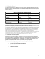
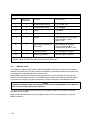
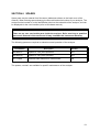
1.8
Calibration - General
For optimum performance, it will be necessary to routinely check the calibration of all of the
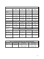
internal gas sensors within the analyser. The recommended periods for each sensor type are
shown in Table 1.2.
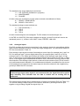
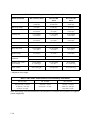
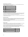
Table 1.2: Recommended calibration periods
Gas sensor module
Low calibration
High calibration
Gfx sensor
weekly
monthly
IR sensor
weekly
daily
Paramagnetic sensor (purity)
monthly
weekly
Paramagnetic sensor (other)
weekly
weekly
Zirconia sensor
monthly
monthly
In addition, the pressure compensation associated with the purity paramagnetic sensor should
be checked annually (the procedure is covered in the Quickstart manual).
The calibration procedure is dealt with in the Quickstart manual. However, this manual details
the requirements for and configuration of calibration ancillaries (such as gases) and (when
autocalibration is used) the connection of solenoid valves, the potential use of the RS232
output and remote initiation switch and the use of Modbus to initiate calibration.
(When the optional external autocalibration or the optional internal autocalibration manifold are
configured and fitted, a manual calibration adjustment or calibration check will use the
autocalibration valves to select the calibration sample gases as required).
1.9
Automatic calibration options
All 4000 series analysers include the software necessary to provide automatic calibrations.
In the case of 'external' autocalibration, external (i.e.: customer supplied) solenoid valves may
be controlled by interrogating the serial output signal or by discrete wiring to relays on the
analyser (ensure that sufficient optional output cards have been installed).
The automatic calibration procedure may be started by any of the following:
•
A user keyboard input
•
A trigger from the internal instrument clock
•
An external contact closure
•
A Modbus command
1.7
NOTES
1.8
SECTION 2 INSTALLATION - GENERAL
2.1
Introduction
NOTE
Sections 2, 3 and 4 provide all the information required to install any 4000 series
analyser. The installer is advised to read all sections completely before commencing
installation.
Installation will only require the use of standard hand tools.
The analyser is suitable for indoor use and may be configured for either bench mount, panel
mount or 19" rack mount.
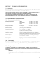
CE MARKING
The 4000 series analysers carry the CE mark which indicates conformity with the
European Directives on CE Marking (93/68/EEC), Electromagnetic Compatibility
(EMC 89/336/EEC) and Low Voltage Directive (LVD 73/23/EEC).
The analyser is rated in accordance with IEC 664 for:
'POLLUTION DEGREE 2' where normally only non-conductive pollution occurs.
'INSTALLATION CATEGORY II', which is characterised as being local level (i.e. not distribution
level), appliances and portable equipment with over-voltage impulse withstand up to
2500 Volts.
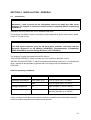
Ambient operating conditions
Parameter
Model
Range
Operating temperature
4100, 4200, 4210
+5°C to +40°C (+41°F to 104°F)
4900
+5°C to +45°C (+41°F to 113°F)
Storage temperature
All
-20°C to +60°C ( -4°F to +140°F)
Atmospheric pressure
All
79 to 124kPaa (11 to 18psia) (for
operating altitudes up to 2000m)
Select a location which allows convenient access for installation and maintenance and will
minimise ambient temperature fluctuations and vibration.
2.1
WARNING
•
The 4000 series analyser is not suitable for use in hazardous areas.
•
The analyser is not suitable for use with corrosive samples.
•
Gases may be toxic or asphyxiant and must be vented to a safe
location. (In the case of the 4200 and 4210 models, gases may also be
flammable)
CAUTION
Install the analyser so that fan and cover vents are not obstructed.
2.2
Unpacking and inspection
WARNING
The 4000 series analysers weigh up to 22kg (45lb) and care must be taken when
handling. It is recommended that they are lifted with hands positioned on either side
of the base of the chassis.
The rack mounting brackets (see Figure 2.1 Item 1) are not designed to be used as handles or
grips. When removing the instrument from its packing, and for subsequent handling, ensure
that the analyser is gripped securely underneath. Lift and remove the analyser from its packing
and inspect for any damage incurred during transit. If damage has occurred, inform Servomex
or its agent immediately. Retain all packing and shipping information. The shipping carton may
be used for future transportion.
After the initial visual inspection, perform the following checks:
1
Check that the specification details table in the front of this manual agree with the
purchase requirements. Pay particular attention to any inserted instrument modification
sheets.
2.
Check that the accessories are present and undamaged.
Standard accessories provided are:
•
Spare mains fuses suitable for electrical power voltage range ordered.
•
Two connectors for wiring to standard chassis signal output plugs (PL1 and
PL5).
•
Electrical power cord with moulded IEC connector or loose IEC connector for
wiring during installation.
Optional accessories are:
2.2
•
Connectors for wiring to each optional signal output plug (PL2 to PL4).
•
Spanner and spare filter elements (for those analysers configured with a
sample filter).
•
Rack mounting slides and kit of parts (See Figure 2.2).
2.3
Bench mount installation
The analyser should be mounted on a sturdy, level surface. The bench mount version has
four feet. If the front two are flipped down, the floats in the optional flowmeters may not rotate,
however, the flow indication will still be correct.
2.4
Panel mount installation
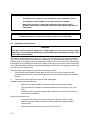
See Figure 2.1 for panel mounting detail. In panel mounting format the analyser is supplied with
a pair of mounting brackets ( item 1) suitable for mounting the front of the instrument against a
panel.
WARNING
The rack mounting brackets are not intended to provide the sole means of support.
The user must provide additional support.
Figure 2.1: Panel mounting detail.
Key:
Note:
1
2
Mounting brackets
Additional Support (customer supplied)
Cut-out dimensions of 447mm x 134mm mounting holes should be M6
or 7mm clearance
2.3
2.5
Rack slide mounting installation
The analyser occupies 3U/5.25"/133mm of rack space. Determine at what height the analyser
is to be installed in the rack enclosure. The analyser will occupy nine rack flange cage nut
positions. Note that intermediate cage nut positions need not be punched out.
If the instrument has been purchased with the rack mounting option then the rack slide inners
will already be mounted on the analyser chassis. If the rack mounting kit has been purchased
as a spare then the instructions in this section detail fitting. The rack mounting kit contains
two slides which have an inner and outer section.
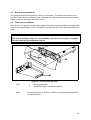
Figure 2.2: Rack installation exploded view
Key:
2.4
1
2
3
4
5
6
Telescopic slide
Screw M5
Slide support bracket
Cage nut
Slide support clamp
Waisted screw, brass, M5
7
8
9
10
11
12
Screw, M4
Washer, M4
Locking washer, M4
Nut, M4
Screw, plated, cross head, M5
Cup washer, plastic
See Figure 2.2. The 19" optional rack slide mount version is supplied with a mounting kit which
includes either long or short slides and rack mounting brackets. Do not attempt to support or
carry the analyser by the rack mount brackets. The analyser is suitable for installation in most
standard rack types including Schroff and Rittall, thus:
•
Remove the inner section from each slide (item 1) and fix one to each side of
the chassis using 3 screws (item 2) for 4902 models or 4 screws (item 2) for
4904 models.
•
Counting from the bottom cage nut position, install cage nuts (item 4) in
positions 1,3,4 and 8 on front two rack enclosure flanges. Install cage nuts in
positions 1 and 4 on rear two rack enclosure flanges.
•
Insert the two waisted screws (item 6) fully into front cage nuts, positions 1 and
4, on both front and rear rack enclosure flanges.
•
Present the slide support clamp (item 5) behind the rack enclosure front flange,
and line up with cage nut positions 1 and 4.
•
Engage the two waisted screws (item 6) in the slide support clamp, but do not
tighten.
•
Fit the slide support (item 3) between the cage nuts (item 4) and the slide
support clamp (item 5), note that the front slide supports face backwards and
the rear slide supports face forwards.
•
Tighten the two waisted screws (item 6) to clamp the slide support (item 3)
between the cage nuts (item 4) and the slide support clamp (item 5).
•
Loosely fit the two rack slide outer sections (item 1), to the slide supports
(item 3) in four places using fixings (items 7,8,9,10). Note that the slide outer
section item 1 should be mounted so that the slide inner (item 1) slides in from
the front.
•
Position the rack slide outer sections (item 1) so that the front edge is 35mm
behind the rack enclosure front flange. Tighten the fixings (items 7,8,9,10).
•
Install the analyser in the rack locating the inner slide section (item 1) inside the
outer slide section (item 1).
•
Secure the analyser into the rack cabinet using the screws (item 11) and the
plastic cup washers (item 12).
2.5
NOTES
2.6
SECTION 3 INSTALLATION - ELECTRICAL
WARNINGS
•
The installer must be satisfied that the 4000 series analyser installation
conforms to the relevant safety requirements, National Electrical Code
and any other local regulations, and that the installation is safe for any
extremes of conditions which may be experienced in the operating
environment of the analyser.
This appliance must be connected to a protective earth.
To comply with the European Community EMC Directives the
interconnecting cables used for all input, analogue output and serial
output should be screened or equivalent protection provided.
For compliance with EMC emissions and susceptibility standards the
functional earth must always be connected to a local EMC ground.
•
•
•
3.1
Electrical power connection
Electrical power is connected to the chassis via an IEC appliance adaptor located on the rear
of the chassis (refer to Figure 1.1). The analyser will already be configured for the mains
voltage range ordered ('110 to 120V' or '220 to 240V').
The analyser should be connected to a clean, single phase electrical power supply meeting the
requirements of 'Installation category II', at a voltage within the range selected. The electrical
power supply should be fused at a value to protect the power cord. The UK power cord already
has a 5A fuse fitted for this purpose otherwise it is recommended that the electrical power
supply is fused at 6A.
The user must ensure that when installed in a rack, cabinet or other fixture, the mains switch
is readily accessible or where this is impractical, the installation must be provided with a
separate means of disconnecting power which complies with the relevant local and national
standards.
Should the user connect a different power cord to the one supplied, this must be wired in
accordance with national and local regulations. After wiring the power cord, check earth
continuity from the power connection earth to the functional earth on the rear of the chassis
(see Figure 1.1).
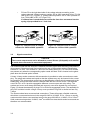
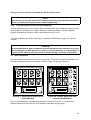
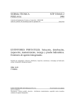
The voltage setting may be changed as follows. The fuse value must be changed when the
voltage setting is changed:
•
Unplug the mains connector.
•
Remove the voltage selector, a screwdriver may be used in the slot at the top of
the voltage selector to aid ejection.
•
Rotate the voltage selector through 180° so that the required voltage is shown
at the bottom of the voltage selector.
3.1
•
Fit fuse F2 to the right hand side of the voltage selector according to the
voltage selected. Voltage selector position 220 to 240V operation fit fuse T3.15A
HBC to IEC 127 (Figure 3.1). Voltage selector position 110 to 120V operation fit
fuse T5.0A HBC to IEC 127 (Figure 3.2).
If a 20mm fuse is used then ensure that the fuse does not extend into the
spring clips provided for a 1 inch fuse.
Figure 3.1: Position of F2 in voltage
selector for 220V to 240V operation
3.2
Figure 3.2: Position of F2 in voltage
selector for 110V to 120V operation
Signal connections
CAUTION
The current outputs must not be allowed to exceed 30vrms (42.4vpeak) or 60 volt DC
to earth when connected to associated equipment.
It is recommended that the analyser is switched off while signal leads are being connected or
disconnected. Signal terminals are located on the rear of the analyser and are identified as
sockets PL1 to PL5. Two sockets PL1 and PL5 are always fitted, PL2, PL3 and PL4 sockets
are present only when the corresponding option cards are fitted. PL8 is located on the gland
plate when the autocal option is fitted.
A loose 14-way socket connector with accessories is provided to make connections to each
plug. The plugs and sockets are keyed so that the sockets may only be located in the correct
plug position. The loose socket covers have an identification number which corresponds to the
mating plug. Ensure that each socket is always fitted with the correct covers. The separate
covers on PL1 to PL4 provide segregation between current output and relay wiring. The
sockets and cover must always be fitted and secured, even when signals are not required.
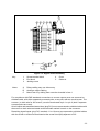
Figure 3.3 shows the assembly of plugs PL1 to PL4 with segregated covers. The assembly for
plug PL5 is similar but with a single 14-way cover provided. Plug PL8 is similar but has only
7-ways.
The loose sockets have screw terminal connections. These will accept a flexible conductor
which has a cross sectional area in the range 20 AWG to 16 AWG, 0.5 to 1.5mm2 or a solid
conductor which has a cross sectional area in the range 20 AWG to 14 AWG, 0.5 to 2.5mm2.
Solid conductors larger than 18 AWG, 1mm2 are difficult to dress inside socket covers and are
therefore not recommended.
3.2
Figure 3.3: Signal socket assembly
Key:
1
2
3
Screw terminal block
End block
Jacking screw
Notes
A
B
C
Relay cabling may use either entry
Analogue output cabling
Mount item 2 by sliding them onto the dovetails in item 1
4
5
Cover
Cable tie
For compliance with EMC standards connections to current outputs must use screened or
shielded cable, with either separately screened pairs or two pairs with an overall screen. The
screens ( or drain wire for foil screens ) must be terminated at pin 1 or pin 6 (both if separate
screened pairs are used).
All mA inputs and associated status lines (plug PL5) must use screened or shielded cables with
the screen or drain wire terminated at the terminals marked 'screen' on the connector.
Remaining signal inputs (plug PL5, terminals 11 to 14) must use screened or shielded cables
with the screen or drain wire terminated at the screen stud (M4) adjacent to PL5.
3.3
The use of screened signal cables is recommended in all installations
After wiring the loose sockets, the covers must be re-fitted for safe operation. To avoid straining
the screw terminal connections attach the cable sheath to the cover by trimming and folding
out the appropriate section of the cover and securing the cable to it using the cable tie provided.
Clip the remaining cover sections into place around the cable.
The loose sockets are provided with end blocks and jack screws which must be fitted and used
to secure them to the corresponding plug. Do not over tighten screws.
The signal terminals each have a legend indicating their function.
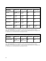
3.2.1
mA output and relay output connections
Plugs PL1 to PL4 provide the analogue output and relay output electrical connections. Refer to
Table 3.1. The option card population may be determined by visual inspection.
Plug PL8 provides additional relay output electrical connections for autocalibration connections
only. Refer to Table 3.2.
WARNING
If the external circuits connected to PL1, PL2, PL3, PL4 and PL8 are at a voltage
exceeding 30Vrms (42.4V peak) or 60V dc the following precautions must be
observed to prevent an electric shock hazard:
a) The external circuits connected to PL1, PL2, PL3, PL4 and PL8 must not be
powered with the connector unplugged.
b) The analyser must be mounted in a rack, enclosure, cabinet or similar fixture and
have the external cabling for PL1, PL2, PL3, PL4 and PL8 secured as close as
practical to the connector. This is to prevent strain on the cable pulling the cover
from the socket.
c) Fit covers to loose sockets.
Do not exceed the specified relay rating of 264V rms maximum and 1A maximum.
NOTE
For reliable operation, relays should switch not less than 10mA.
3.4
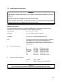
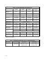
Table 3.1: Signal terminal location PL1 to PL4
Terminal
number
PL4
PL3
PL2
(optional)
(optional)
(optional)
PL1
14
Screen
Screen
Screen
Screen
13
Relay 4.5A
Relay 3.5A
Relay 2.5A
Relay 1.5A
12
Relay 4.5A
Relay 3.5B
Relay 2.5B
Relay 1.5B
11
Relay 4.4A
Relay 3.4A
Relay 2.4A
Relay 1.4A
10
Relay 4.4B
Relay 3.4B
Relay 2.4B
Relay 1.4B
9
Relay 4.3A
Relay 3.3A
Relay 2.3A
Relay 1.3A
8
Relay 4.3B
Relay 3.3B
Relay 2.3B
Relay 1.3B
B
o
t
t
o
m
7
Screen
Screen
Screen
Screen
6
Screen
Screen
Screen
Screen
5
mA 4.2 -
mA 3.2 -
mA 2.2 -
mA 1.2 -
4
mA 4.2 +
mA 3.2 +
mA 2.2 +
mA 1.2 +
c
o
v
e
r
3
mA 4.1 -
mA 3.1 -
mA 2.1 -
mA 1.1 -
2
mA 4.1 +
mA 3.1 +
mA 2.1 +
mA 1.1 +
1
Screen
Screen
Screen
Screen
T
o
p
c
o
v
e
r
Table 3.2: Optional external autocalibration connections PL8
Terminal
Function
1
Screen
2
Relay 0.1B
Default relay contacts for group 1 valve 1
3
Relay 0.1A
Sample / Calibration selection (if fitted)
4
Not Used
5
Relay 0.2B
Default relay contacts for group 1 valve 2
6
Relay 0.2A
Cal. Gas 1 / Cal. Gas 2 selection (if fitted)
7
Screen
3.5
The standard relay output defaults are as follows:
1.3
1.4
1.5
CAL IN PROG (Calibration in progress)
MAINTENANCE
FAILURE
All other relays are unassigned, except (where external autocalibration is fitted):
0.1
0.2
GROUP 1 SAMPLE/CAL
GROUP1 CAL1/CAL2
The standard analogue output defaults are:
1.1
1.2
2.1
2.2
TXD (transducer) 1
TXD 2
TXD 3
TXD 4
All other extra analogues are unassigned. The R1 defaults for each analogue are:
L=0%FSD, U=100%FSD (Gfx's have variable low ranges, so their R1 limits will need to be
individually set in L1), 4-20mA, LOW LIMIT 3.6mA, FREEZE, JAM LOW
3.2.2.
Analogue inputs
Plug PL5 provides the electrical connections for the analogue inputs, the autocalibrate initiate
input (function detailed in Section 3.4) and the range change input. The connection details for
PL5 are summarised in Table 3.3.
Each analogue input signal consists of an analogue current input (for example pins 1 and 2 on
PL5 for analogue input 1) plus a digital status input (for example pins 9 and 10 on PL5 for
analogue input 1). The status input defines the validity of the analogue input signal. A high
input, or open circuit, on the digital signal indicates that the data is invalid. A low input, or short
circuit, on the digital signal indicates that the data is valid. Connection in this way ensures that
disconnection of the analogue input source or removal of the connector from PL5 will result in
an invalid measurement indication. If no suitable status indication is available from the source
of the analogue input signal then the status input pin should be shorted to the neighbouring
ground pin within the PL5 connector.
NOTE
If the analogue input status signal is not connected then the digital line will be pulled
high internally. This indicates that the data is invalid and no reading will be
measured.
The external range change input is located at pins 13 and 14 of connector PL5 (see Table 3.3).
The second analogue output range for all outputs is obtained by shorting these two pins
together or by providing a digital low signal to pin 14.
3.6
Table 3.3: Signal terminal location PL5
Terminal
3.2.3.
Function
Terminal
Function
1
Analogue input 1 +ve
8
0V
2
Analogue input 1 -ve
9
Analogue input 1 valid
3
Analogue input 2 +ve
10
0V
4
Analogue input 2 -ve
11
0V
5
Screen
12
Auto calibration initiate
6
Screen
13
0V
7
Analogue input 2 valid
14
Range change
External autocalibration connection
The external autocalibrate initiate input is located at pins 11 and 12 of connector PL5. The
autocalibration facility is started by shorting these two pins together or by providing a digital low
signal to pin 12.
NOTE
The external autocalibration initiate signal should be applied for at least 2 seconds,
(but less than 30s) to ensure that the input has been recognised.
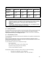
For analysers configured with the external autocalibration option card, an additional output
connector, PL8, is fitted into the sample gland plate at the rear of the analyser. This connector
supplies two pairs of relay contacts which may be used to control external valves.
The following truth table applies to any pair of relay contacts utilised for autocalibration. These
relay contacts are rated at 1.0A, 264V AC and 1.0A, 30V DC (non-inductive). Screened cable
should be used to connect to solenoid valves of length not exceeding 3m with the screen
terminated at the instrument end. It will be necessary to fit a suppression device across the
coils of the solenoid valves. For DC supplies a diode is recommended. For AC supplies a
0.047uF capacitor in series with a 100Ω resistor would generally be found satisfactory.
3.7
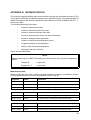
Table 3.4: External autocalibration truth table
Gas Required
Relay Contacts for
Valve 1
Relay Contacts for
Valve 2
Sample Gas
De-energised (OPEN)
De-energised (OPEN)
Calibration gas 1
Energised (CLOSED)
De-energised (OPEN)
Calibration gas 2
Energised (CLOSED)
Energised (CLOSED)
Depending on the number of autocalibration groups, at total of 2, 4, 6, or 8 relays will be needed
to control up to eight external valves. The relay output electrical connections can be made to
any combination of PL1, PL2, PL3, PL4 and PL8. Refer to Quickstart manual for autocalibration
set up, this will automatically clear any existing relay allocation. Table 3.1 and 3.2 contain the
pin out details.
3.3
Serial data/Modbus connection
The serial data connection is provided via the 9 pin 'D' type connector (PL6) located on the rear
of the instrument. Both RS232 and RS485 interfaces are supported as shown in Table 3.5
NOTE
The RS232 and RS485 interfaces are non-isolated. When using the RS485 interface
with other non-isolated equipment, the difference in ground potentials must be no
greater than ±7V.
For compliance with EMC standards, connections to PL6 must be made using a screened
cable. The screen must be terminated at the EMI shielded 'backshell' or conductive cover of
the 'D' type connector. Maximum total cable lengths are 3 metres for the RS232 interface, and
1200 metres for the RS485 interface. Note that the 4000 analyser includes RS485 line
termination of 120 Ω.
Table 3.5: Serial output connections PL6
Interface
Terminal
RS232
2
Received data (RXD)
3
Transmitted data (TXD)
5
Signal common/ground
1
RS485- (B)
6
RS485+ (A)
RS485
Function
The serial data connection can be used in one of two ways. With the analyser configured to
"Continuous" communications mode (refer to Quickstart manual) a data frame is transmitted at
user-defined intervals. With the mode set to "MODBUS ASCII" or "MODBUS RTU" the analyser
becomes a Modbus slave responding to commands or data requests from a Modbus master.
These communications modes are described in more detail in the following sections.
3.8
3.4
Continuous mode
In continuous mode a data frame is transmitted by the serial output port at a user defined
interval. The format of the data frame is given in Table 3.6 and 3.7. However, it is a list of
process variables (or 'fields') preceded by a start character, separated by semi colons and
terminated by carriage return and line feed, i.e.:
A;B;C;D;E;F;G;H;I;J;K;L;M;............;N;<CR><LF>
The frame frequency and generic communications parameters are configured in the analyser
software (refer to Quickstart manual), note the 'frame frequency' sets up the frequency of
transmission of the data frame down the serial communications port. For example if the value
is set to 15 seconds then the output data frame will be transmitted once every 15 seconds. The
frequency is set in steps of one seconds from 1 to 9999 seconds. If the value is set to zero then
the transmission of data down the serial port stops and will not restart until a non zero value is
entered.
Table 3.6: Serial output data frame, start and end sequences
Field
Number of
characters
Function
Entry/format
A
8
date
DD-MM-YY
B
8
time
HH:MM:SS
C
2
analyser failure and
maintenance fault status
first character F for failure, second
character M for maintenance
(spaces = OK)
D
8
Autocalibration 'flags',
two characters for each
of the four calibration
groups
first character: group 1, S for
sample, C for calibration gas
second character: group 1, 1 for
cal gas 1, 2 for cal gas 2
etc, for groups 2, 3 then 4
E
2
F-M
number of process
measurements or
'variables'
03 to 07, the following fields will be
repeated for each transducer and
any derived measurements. The
last two variables will always be
the two external inputs (E1, E2)
measurement sequences, refer to Table 3.7
N
4
check sum
e.g.: 096A
-
-
end code, <CR> and
<LF>
ASCII code 13 and 10
3.9
Table 3.7: Serial output data frame, measurement sequences
Field
Number of
characters
Function
Entry/format
F
2
measurement identity
e.g.: I1 , D1 , E1
G
6
measurement name
e.g.: Oxygen
H
6
value
e.g.: 20.9
I
3
units
e.g.: %
J
4
alarms
one character for each alarm,
1,2,3,4 raised = alarm,
space = OK
K
2
failure and maintenance
fault status
first character F for failure,
second character M for
maintenance (spaces = OK)
L
1
calibration status
C in calibration, or space
M
1
warming up status
W warming up, or space
The above will be repeated for each measurement, (including derived) concluding with
external inputs E1 and E2, before returning to end sequence.
3.5
Modbus mode
The analyser supports both Modbus ASCII and Modbus RTU protocols (refer to Quickstart
manual). Note that the serial port settings are shared by all communication modes and must
be configured to valid settings for the mode in use.
Both RS232 and RS485 connections are provided and may be selected through the user
interface (see Quickstart manual). The RS485 option also allows multidrop operation where
more than one analyser may be connected to a single serial port on the Modbus master.
NOTE
In RS485 multidrop mode, each analyser must have a unique Modbus slave address.
This can be set through the user interface.
In RS232 mode, a dedicated connection to the Modbus master is required and multidrop
operation is not possible.
Appendix B describes how to access analyser data and control autocalibration using the
Modbus protocol.
3.10
3.6
EMC Installation
The chassis must be securely bonded to the local EMC ground. In most installations this will
be the back plate, cabinet walls or other access point to the local equipotential common
bonding network. Connection to the analyser should be made using the shortest possible
length of heavy-gauge braid. The braid should be clamped between the cable clamping
washers provided on the functional earth terminal. This is an M5 stud located to the rear of the
analyser, see Figure 1.1.
Interconnecting cables used for all input, analogue output and serial output should be
screened, or equivalent protection provided, as described in Sections 3.2 and 3.3.
All cables should be routed along a low resistance parallel earth conductor to divert earth
currents and allow the screened cables to be grounded at both ends.
The whole EMC ground bonding network should follow best practice so that the back plate,
cabinet walls, parallel earth conductors and other structural elements of the installation form an
equipotential common bonding network. The network should be connected as directly as
possible preferably using metal-to-metal bonding at multiple points. Bonds should make good
reliable low-resistance connections.
3.11
NOTES
3.12
SECTION 4 INSTALLATION – GAS CONNECTIONS
4.1
Introduction
Sample and calibration gases pass into and out of the chassis via a gland plate mounted on
the rear of the chassis. The sample gland plate with or without external autocalibration provides
up to four sample inlets and a corresponding outlet for each inlet, and an optional interface
connector, PL 8. When optional internal paramagnetic autocalibration solenoid valves are used
a manifold is mounted on the sample gland plate which provides ports for sample inlet and
outlet, and inlets for low and high calibration gases for gas sensor module 1 only.
•
•
4.2
CAUTION
The condition of the gases supplied to the analyser depend on the analyser
configuration. Full details are given in Section 7.
Failure to comply with the specifications will result in damage to the
analyser.
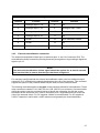
Calibration gases
The gas mixtures recommended for calibration of the instrument will depend on the gas
components measured by the transducers fitted to the gas stream and the measurement
ranges of the transducers. The recommended gases are limited by the long term storage
stability of the components of the mixture. Certain gas mixtures should be avoided as these will
not be stable with time. For example gas mixtures containing (all of the following) O2 and NO
are not stable and should not be used.
Note, the 4900 analyser permits several sensors to be on a single sample stream. In such
cases the selection of calibration gases for use with either internal or simultaneous external
autocalibration will either have to facilitate the requirements of several transducers at the same
time or be controlled by their own relay/solenoid. Examples of calibration gases (particularly for
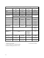
use with Gfx arrangements) are shown in Table 4.1, below.
4.1
Table 4.1: 4900C calibration gas examples
Gas components measured
Calibration gas 1
Calibration gas 2
CO only or CO+O2
"zero grade" N2*
CO in air gas mix
CO+CO2 or CO+CO2+O2
"zero grade" N2
CO+CO2 in air gas mix
NO only or NO+O2
NO in N2 gas mix
Air
NO+CO2 or NO+CO2+O2
NO in N2 gas mix
CO2 in air gas mix
SO2 only or SO2+O2
"zero grade" N2*
SO2 in air gas mix
CO+NO or CO+NO+O2
NO in N2 gas mix
CO in air gas mix
CO+SO2 or CO+SO2+O2
"zero grade" N2*
CO, SO2 in air gas mix
NO+SO2 or NO+SO2+O2
NO in N2 gas mix
SO2 in air gas mix
Note: the following presumes that background gases, in the typical sample stream, will have
no effect on the sensor readings. If this is not the case, calibration gases should be modified
accordingly.
4.2.1
Gfx transducer low and high calibration
The low calibration gas for Gfx gas sensor modules may be specified between -5vpm and
+5vpm of the measured component. Zero grade nitrogen is recommended.
The high calibration gas can be in the range 6 to 110% of the transducer's FSD. As Gfx sensors
are configured as 'dual range' units, it is recommended that the high calibration gas is selected
at the top end of the range used.
4.2.2
IR transducer low and high calibration
Typically zero grade nitrogen is recommended for low calibration.
It is recommended that the high calibration gas is in the range 80 to 110% of the transducer's
FSD.
4.2.3
Paramagnetic transducer low and high calibration
The low calibration gas for paramagnetic gas sensor modules may be specified between -3%
and +3% oxygen. This is to allow for the situation where the background gas affects the
paramagnetic zero (see Appendix A). Zero grade nitrogen is recommended.
The high calibration gas can be in the range 5 to 100% oxygen. For purity measurements a
high calibration gas with approximately 100% oxygen is recommended, for other paramagnetic
transducers 21% (air) is adequate.
4.2
This gas can also be used to calibrate the Pm Pressure sensor.
NOTE
Pure dry air can be used, but not if it has been passed through molecular sieve driers
since its composition may have been altered significantly.
4.2.4
Zirconia transducer low and high calibration
The low calibration gas must be a high quality certified mixture of pure background gas (usually
nitrogen N6.0) containing trace oxygen. Mixtures containing between 100 and 1000vpm
oxygen are preferred, however, lower concentrations may be used.
The high calibration gas must be pure dry air containing 209500vpm oxygen (i.e. 20.95%
volume).
CAUTION
It is essential that all gases supplied to zirconia transducers are filtered to 2µm local
to the analyser and that great care is taken to ensure that there is no possibility of
ingress of dirt, swarf or any other kinds of particle during connection or operation.
4.3
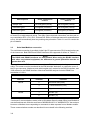
Gas connections
Gas connections are made to the rear of the analyser. The actual connection depends on the
analyser variant and the sensor selection. Refer to Table 4.2 through Table 4.4.
Figure 4.1: Sample gland plate without
autocalibration
Figure 4.2: Sample gland plate with
internal autocalibration
Note, the gland plate for external autocalibration is similar to Figure 4.1, except that an
additional electrical connector (PL 8) is installed underneath the gas ports.
4.3
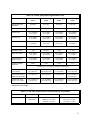
Table 4.2: 4100C and 4200C sample port vs transducer type
Gas sensor
module type
Sample inlet
Sample outlet
Low cal gas
High cal gas
Zirconia
1/8" OD*
stainless steel
stub
1/4" NPT
N/A
N/A
1/8" NPT
1/4" NPT
N/A
N/A
female
female
1/8" NPT
1/4" NPT
N/A
N/A
female
female
1/8" OD*
stainless steel
stub
1/4" NPT
N/A
N/A
1/8" NPT
1/4" NPT
1/8" NPT
1/8" NPT
female
female
female
female
1520 Series IR
Paramagnetic
Infrared Gfx
Internal auto cal
female
female
*Note: An external filter may be specified, in which case the inlet connections will be
'Swagelok' 1/8" OD female compression. The filter should be fitted directly to the analyser inlet
or, if preferred, at a convenient point in the sample inlet line.
Table 4.3: 4210C sample port type
Gas sensor
module type
Sample inlet
Sample outlet
Low cal gas
High cal gas
All sensor types
1/8" OD*
stainless steel
stub
1/8" OD*
stainless steel
stub
N/A
N/A
*Note: An external filter may be specified, in which case the inlet connections will be
'Swagelok' 1/8" OD female compression. The filter should be fitted directly to the analyser inlet
or, if preferred, at a convenient point in the sample inlet line.
4.4
Table 4.4: 4900C sample port type
Gas sensor
module type
Sample inlet
Sample outlet
Low cal gas
High cal gas
Standard
1/8" NPT
1/4" NPT
N/A
N/A
female
female
1/8" NPT
1/4" NPT
1/8" NPT
1/8" NPT
female
female
female
female
With internal Auto
Calibration
WARNING
•
•
4.4
Verify that connections are leak free at full operating pressure before applying
sample or calibration gases. These gases may be flammable, toxic or
asphyxiant.
Consideration should be given to the flammable, toxic and asphyxiant nature
of the sample gas when selecting a vent location.
Reading flowmeters
The optional flow monitors are provided to control and measure the flow of sample gas through
the analyser. The flow monitor consists of an optional needle valve (4900C only) and a
rotameter type flowmeter. The reading of the flow rate through the flowmeter is obtained by
observing the scale indication at the top of the float.
4.5
Autocalibration overview
The autocalibration facility allows the instrument's calibration to be updated or checked without
user intervention.
When external autocalibration valves or an internal autocalibration manifold are fitted, a
manual calibration adjustment or calibration check will use the autocalibration valves to select
the calibration sample gases as required.
The autocalibration process can be initiated in four ways:
by an internal timer;
by an external contact closure (refer to Section 3.4);
by operator request through the user interface;
or by an external Modbus command.
Autocalibration facilities are offered to either measure or check the following:
•
•
Transducer low calibration ( 'zero' calibration ).
Transducer low and high calibration ( both 'zero' and 'span' ).
4.5
In autocalibration two user defined gases (cal gas 1 and cal gas 2) are provided to the
instrument. These gases may be either for low or high calibration of the transducers. In some
cases the same gas may be used for low calibration of one transducer while being the high
calibration of another. The gases are introduced to the analyser in three phases:
Phase 1
cal gas 1
Phase 2
cal gas 2
Phase 3
cal gas 1 again.
Any of the transducers connected to any sample inlet may be autocalibrated, either
simultaneously or, by the use of calibration groups (see later in this section), completely
independently.
NOTE
In the 4900C analyser, internal autocalibration can only be configured to calibrate all
of the transducers on stream 1.
The following parameters must be set up for either autocalibration or autocheck:
•
•
•
•
•
•
•
•
•
The time and date must be correctly set before using autocalibration.
Selection of 'LOW' or 'LOW & HIGH' autocalibration (zirconia sensors cannot have a
high autocalibration).
LOW and HIGH calibration gas concentrations.
Autocalibration period (i.e. time interval between successive autocalibrations; minimum
one hour, maximum 59 days + 24 hours).
Date and time of start of cycle (first autocalibration).
Flush Time - this may be set, to suit the installation, to a value between 0.5 and 16
minutes so that each gas concentration stabilises before being read. After each flush
time the gas will flow for an additional minute to allow the new 'calibrated' level to be
viewed or recorded.
Selection of autocalibration or autocheck.
Calibration gas relays (if analyser relays are to be used, the alternative being control by
external monitoring of the RS-232 output).
It is necessary to specify which calibration gas (1 or 2) is used for the LOW calibration of
each sensor.
Calibration groups
Autocalibration allows up to four independently programmable transducer groups. Groups of
transducers are programmed independently but only one autocalibration can be performed at
any one time. A queuing mechanism is used to ensure that autocalibrations are performed as
soon as possible, if another autocalibration was taking place at the intended start time.
Autocalibrations initiated by the internal timer, the user interface or by Modbus commands may
specify an individual calibration group. Autocalibrations initiated by an external contact closure
will be carried out on all groups in sequence (it effectively causes all groups to be placed in the
queue in sequence). Autocalibration will only be performed for non-empty groups that are
enabled, and have their gas control relays assigned. This input will be ignored if an
autocalibration is already in progress.
4.6
4.6
Autocalibration valve installation
As a general guide, two externally powered three way valves are required for each transducer
to be calibrated. One switches between sample gas and the second 'calibration' valve (which
switches between calibration gas 1 and calibration gas 2).
Autocalibration valves may be controlled either by the RS232 output (see Section 3.3) or by
relays on the rear panel of the analyser (refer to Section 3.2 and Section 3.6).
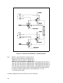
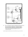
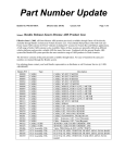
Figure 4.3 and Figure 4.4 show typical installations and assume that, in the de-energised
states, the lower port on the valves will be normally open (NO). The latter figure actually
demonstrates the potential to utilise independent autocalibration even when several
transducers are on a single sample stream (ref 4900C).
NOTE
The CAL1/CAL2 valve is only used during calibration. In the case of fully
independent autocalibration, it is permitted to connect all CAL1/CAL2 valves to one
relay, and configure the software accordingly. However, a dedicated SAMPLE/CAL
solenoid/relay is required for each group.
4.7
Figure 4.3: External autocalibration - parallel systems
Key:
INLET 1, gas connection to analyser inlet 1
INLET 2, gas connection to analyser inlet 2
SAMPLE A, gas connection to sample gas 1
SAMPLE B, gas connection to sample gas 2
CAL1 (A), gas connection to calibration gas 1 associated with transducer 1
CAL2 (A), gas connection to calibration gas 2 associated with transducer 1
CAL1 (B), gas connection to calibration gas 1 associated with transducer 2
CAL2 (B), gas connection to calibration gas 2 associated with transducer 2
A, wiring to analyser option board, in this example PL8 (external autocal)
B, wiring to analyser option board, in this example PL1, 2, 3 or 4
C, external power supply
A similar arrangement may be used for up to four inlet ports.
4.8
Figure 4.4: External autocalibration - stream systems
Key:
INLET 1, gas connection to analyser inlet 1SAMPLE, gas connection to sample gas
CAL1 (A), gas connection to calibration gas 1 associated with transducer 1
CAL2 (A), gas connection to calibration gas 2 associated with transducer 1
CAL1 (B), gas connection to calibration gas 1 associated with transducer 2
CAL2 (B), gas connection to calibration gas 2 associated with transducer 2
A, wiring to analyser option board, in this example PL8 (external autocal)
B, wiring to analyser option board, in this example PL1, 2, 3 or 4
C, external power supply
A similar arrangement may be used for up to four transducers on up to two inlet ports.
4.9
4.7
Power up
WARNING
Conditions for safe use with flammable samples (4200 and 4210):
Do not operate the power switch on the rear panel of the analyser if the unit is known
to contain a flammable sample mixture.
The 4200 or 4210 must not be used in the event a display failure is observed.
The analyser may now be powered up. Please refer to the Quickstart manual for details of
analyser set-up.
4.10
SECTION 5 ROUTINE MAINTENANCE
5.1
Replacing fan filter element
The external fan filter element should be checked every six months in laboratory conditions, for
environments with a high dust content this period should be reduced. The filter element is
washable and in laboratory or light dust conditions may be washed and refitted rather than
replaced.
•
Remove power from the analyser and unclip the filter cover complete with filter
element and plastic gauze.
•
Remove the plastic gauze and old filter element from the cover.
•
Fit new filter into cover followed by plastic gauze.
•
Clip cover back onto fan.
CAUTION
After washing the filter, ensure that it is completely dry before refitting.
5.2
Replacing the sample filter element
The front panel sample filter elements should be replaced every six months. External filter
elements may be replaced annually, or more frequently if necessary.
WARNING
Sample and calibration gases may be toxic or flammable. Stop sample flow into
analyser to avoid releasing gas into atmosphere when sample filter cap is removed.
1.
Stop sample flow to analyser.
2.
Use spanner (provided for front panel filter) to unscrew sample filter cap. Support the
body of the external unit as necessary.
3.
Remove old filter element and, on front panel filters only, the rubber 'O' ring. (The external
element may be tapped lightly on the side to break it loose from the tapered seating area).
4.
Fit new sample filter and (internal units only) rubber 'O' ring. Check that rubber 'O' ring is
properly seated on the filter cap. (The external element should be tapped lightly with a
smooth faced tool to reseat).
5.
Fit sample filter cap and tighten using spanner.
6.
Verify that there are no leaks by testing with a proprietary leak detection solution.
5.1
5.3
Cleaning
The exterior of the analyser should be regularly cleaned using a slightly damp cloth. Remove
power before cleaning. Ventilation holes must be kept clear. Do not use solvents or abrasive
cleansers to clean the analyser.
5.4
Toxic/flammable samples - routine leak test
WARNING
If toxic and /or flammable samples are being analysed it is essential to check the
analyser and associated sample lines/system for leaks (every 6 months). MAX
pressure that may be applied to each module is 8psig (5psig for the 4900C), however,
this must be applied and removed slowly to both the inlet and outlet simultaneously
to avoid damage to the measuring sensors.
5.2
SECTION 6 SPARES
Spare parts may be ordered from Servomex (addresses shown on the back cover of the
manual). When ordering spares always give the model and serial number of your analyser. The
analyser serial number is on the identification label on the underside of the analyser, and can
be displayed via the user interface (refer to Quickstart manual).
WARNING
There are no user serviceable parts inside the analyser. Refer servicing to qualified
personnel. Removal of the enclosure lid may invalidate the instrument warranty.
The following spares are required to maintain normal operation of the analyser.
Part Number
Description
Quantity
S4100KITA
Spares kit, one years operation
1EA
S4100KITB
Spares kit, two years operation
1EA
2377-3848
Stainless steel element for external filter
A/R
The spares, overleaf, are available for specific maintenance of the analyser.
6.1
Part Number
6.2
Description
Quantity
04000003C
QuickStart operator manual, English
1 ea
04000013C
QuickStart operator manual, French
1 ea
04000023C
QuickStart operator manual, German
1 ea
04000033C
QuickStart operator manual, Spanish
1 ea
04000005C
Installation manual, English
1 ea
04000015C
Installation manual, French
1 ea
04000025C
Installation manual, German
1 ea
04000035C
Installation manual, Spanish
1 ea
04000002C
Service manual, English
1 ea
S4000976
Kit, four tip up feet.
1 pk
S4000978
Mains fuses for 170-264V operation
1 pk
S4000979
Mains fuses for 85-132V operation
1 pk
S4000986
Kit socket 14W signal
1 ea
2388-1981
Filter element, 80mm Sq fan
1 pk
S4000984
Rack mount kit, short chassis
1 ea
S4000985
Rack mount kit, long chassis
1 ea
S4000987
Kit, internal fine filter cap and 'o' ring
1 ea
S4000988
Kit, internal filter elements 6µM
1 pk
2377-3831
Stainless Steel filter unit, complete (external)
1 ea
SECTION 7 TECHNICAL SPECIFICATIONS
7.1
Introduction
This section includes the technical specifications for all versions of the 4000. The user must
ensure that the relevant sub-sections are used for reference.
It may be noted that similar transducer options are available in different analyser variants, in
some cases the specifications for these will be application dependent.
(This performance specification has been written, and verified, in accordance with the
international standard IEC 1207-1:1994 "Expression of performance of gas analysers").
7.2
7.2.1
Generic 4000 series analyser performance
Environmental specifications
Operating temperature:
4100C
4200C/4210C
4900C
Storage temperature:
All analysers
Relative humidity:
10 to 90% HR, non-condensing.
Atmospheric pressure:
79 to 124kPaa / 11 to 18psia
(for operating altitudes to 2000m)
Installation category:
II (local level power distribution with over voltage to
withstand up to 2500Volts) in accordance with IEC 664
Pollution degree
2 (normally electrically non-conducting pollutants) in
accordance with IEC 664
Warm up time:
Typically 1 hour from cold start at 20°C/68°F.
7.2.2
5 to 40°C / 41 to 104°F
5 to 40°C / 41 to 104°F
5 to 45°C / 41 to 113°F
-20 to 60°C / -4 to 140°F
Power supply
The analyser is CSA/FM Approved for only 110-120 / 220-240Vac (+/-10%),50/60Hz, 350VA
maximum, but will function correctly for 85-132/170-264Vac,47-62Hz, 350VA maximum.
7.2.3
Design standards
The analyser complies with the "CE Marking Directive" 93/68EEC and conforms to the
following normalised European standards for performance, product safety and electromagnetic
compatibility:
EN61010-1
Safety requirements for electrical equipment for measurement, control and laboratory
use.
7.1
EN61326+A1
Electrical equipment for measurement, control and laboratory use - EMC
requirements.
7.2.4
Analogue outputs
Two isolated 0-20mA/4-20mA output with full zero and span adjustment as standard.
The user may define a second range by means of an external contact closure.
A maximum total of eight, two range outputs are available by selecting option cards.
Maximum impedance for each output is 1KΩ.
Maximum output current for each output is 20.5mA.
Maximum output voltage for each output is 27V.
7.2.5
Alarms
Three "volt free" single pole relay contacts rated at 264Vac/30Vdc @ 1.0Amp as standard.
Nine further general purpose relays are available by selecting option cards, however only
four concentration alarms may be assigned to one transducer.
(Two similar relays are available as part of the 'external autocalibration' option. These contacts
are used exclusively to control solenoid valves).
7.2.6
Serial data/Modbus connection
Single RS232/RS485 serial port, user configurable from 2400 to 19200 baud. This may be used
as an ASCII data logging output or for communication using the Modbus protocol.
7.2.7
Analogue inputs
Two 'floating' (maximum common mode voltage 13V) 4-20mA/0-20mA linear inputs.
Associated digital input per channel to indicate data validity.
Intrinsic Error <0.02mA.
7.2.8
Digital inputs
Analogue input 1 valid.
Analogue input 2 valid.
Analogue outputs range change (contact closure).
Auto calibration initiate (contact closure).
7.2
7.2.9
Sample wetted materials
The following tables list sample wetted materials, firstly by sensor type, then by analyser model
and configuration.
Table 7.1: Sample wetted materials
Material
Sensor type:
Paramagnetic
Zirconia
1210
series
GFx
1520
series
IR
Basic
Control
Purity
Stainless Steel 303
9
9
9
9
9*
9*
Stainless Steel 316
9
9
9
9
9
9
Viton
9
9
9
9
9
9
9
Polypropylene
Borosilicate glass
9
9
9
Platinum
9
9
9
Platinum Iridium alloy
9
9
9
9
9
Electroless Nickel
Polyphenylenesulphide
(PPS) carbon/PTFE filler
9
Stainless Steel 310
9
Alumina
9
Yttria Stabilsed Zirconia
9
Nickel Iron
9
Sealing glass
9
Gold
9
9
Calcium Fluoride
9
Nickel
9
Sapphire
9
Epoxy resin
9
*not in 4210 analysers
7.3
Table 7.2: Sample wetted materials, continued
Feature
Analyser
Additional materials
Flow driven options
4100
4200
Polypropylene
Pressure driven options
4100
4200
Polysulphone
Polypropylene
Stream systems
4900
Polysulphone
Polypropylene
Nylon*
Flowmeters
4100
4200
4900
Borosilicate Glass
Duralumin
Needle valves
4900
Brass
Fomblin Grease (suitable for oxygen service)
Flow alarm
4100(1)
4900
Glass
Nylon
Silicon Rubber
Aluminium
Internal filter
4100
4200
4900
Polycarbonate
Glass Fibre
External filter
4100
4200
4210
316 Stainless Steel
Internal Autocal
4100
4900
Aluminium
PVDF
* - not in sample streams that include a Gfx
For the 4100 analyser go to page 7.5.
For the 4200 analyser go to page 7.9.
For the 4210 analyser go to page 7.12.
For the 4900 analyser go to page 7.15.
(1) This is only available on 4100C (Gfx flow driven) and 4900C product.
7.4
7.3
4100C analyser performance
WARNING
This analyser (4102C and 4104C) is not suitable for use with flammable or corrosive
samples.
Internal autocal is unsuitable for use with toxic samples.
If toxic samples are present, the maximum pressure to the analyser must be limited
to 8psig by means of a suitable pressure release system.
Sample requirements
For best performance the flow, or pressure, supplied to the analyser should be kept at a
constant value for both normal sampling and for calibration gas input.
Temperature:
5 to 40°C / 41 to 104°F
Dew point
5°C / 9°F below minimum ambient
Condition:
Oil free, non - condensing, filtered to 2µm
Vent:
Each sensor outlet should be connected to a separate
atmospheric vent, free from any back-pressure.
(Consideration should be given to the toxicity and
asphyxiant nature of the sample gas when selecting a
vent location).
a)
b)
Flow driven options:
IR :
Pm Purity:
Pm Control:
Pm Basic:
Zr:
Gfx:
100 (min) 100 (min) 100 (min) 10 (min) 200 (min) 500 (min) -
250 (max) ml/min
250 (max) ml/min
250 (max) ml/min
100 (max) ml/min
400 (max) ml/min
2500 (max) ml/min
nominal
min.
5psig / 35kPa
2psig /14kPa, max. 8psig /56kPa
All pressure driven options:
CAUTION
Do not exceed the rated flow or pressure as sensor damage may result.
7.5
Table 7.3: 4100C performance specification, oxygen
Pm1111E O2
Basic
Pm1158 O2
Control
4100995 O2
Purity
Zr 704 O2
Trace
Range
0-25%
0-100%
0-100%
0-210000 vpm***
Min.rec.o/p range
0-5%
0-5%
0-0.5%
0-5 vpm
Intrinsic error
<0.15%
<0.15%
<0.02%
<0.1 vpm O2**
Linearity error
<0.1%
<0.05%
<0.05%
<0.1 vpm O2†
Gases measured
inherently linear, dependant on calibration gases
Repeatability
<0.1%
<0.1%
<0.01%
<0.1 vpm O2†
Response (T90)
<15 s at
100ml/min
<15 s at
200ml/min
<12 s at
200ml/min
<15 s at
400ml/min
Zero drift / week
0.1% O2
0.05% O2
0.01% O2
<1% of reading
or 250 vpb*
Span drift / week
0.1% O2
0.1% O2
0.02% O2
<1% of reading
or 250 vpb*
Output fluctuation
(peak to peak)
<0.1% O2
<0.05% O2
<0.01% O2 (in the
range 99-100%)
<0.5% of reading
or 10 vpb*†
Cross sensitivity
no effects in target applications
5 vpm H2,
5 vpm CO,
5 vpm CH4
all <1 vpm O2
Ambient pressure
coefficient
directly proportional to analyser vent
pressure
<0.003% of
reading for a 1%
change in
analyser vent
pressure
no effect
Ambient temp. coeff./
10°C change
2% of reading or
0.5% O2
1% of reading
or 0.1% O2
0.2% of reading
or 0.02% O2
1% of reading
or 10 vpb*
Inlet sample pressure
effect from 2 to 8psig
<2% of reading
or 0.2% O2*
<2% of reading
or 0.1% O2*
<0.1% O2
<0.15% of reading
or 0.1% vpm*
Sample flow effect
over full flow range
<2% of reading
or 0.2% O2*
<2% of reading
or 0.1% O2*
<0.1% O2
<0.15 vpm or
<2 % of reading*
* whichever is the larger
** derived, dependant on calibration gases
*** indicative reading given above 21% O2
7.6
†
in the range 0-100vpm
Table 7.4: 4100C performance specification, Gfx
Gases measured
Gfx 1210 CO
Trace
Gfx 1210 CO2
Trace
Gfx 1210 N2O
Trace
Gfx 1210 CH4
Range (higher are
available)
0-50 vpm
0-10 vpm
0-50 vpm
0-50 vpm
Min.rec.o/p range
0-10 vpm
0-5 vpm
0-10 vpm
0-10 vpm
Intrinsic error
<1% of reading
or 0.5 vpm*
1% of reading
or 0.1 vpm*
1% of reading
or 0.5 vpm*
1% of reading
or 0.5 vpm*
Linearity error
1% of reading
or 0.5 vpm*
1% of reading
or 0.1 vpm*
1% of reading
or 0.5 vpm*
1% of reading
or 0.5 vpm*
Repeatability
1% of reading
or 0.5 vpm*
1% of reading
or 0.1 vpm*
1% of reading
or 0.5 vpm*
1% of reading
or 0.5 vpm*
Response (T90)
Trace
<20sec at 2000ml/min
Zero drift / week
1 vpm
0.2 vpm
1 vpm
1 vpm
Span drift / week
2% of reading
or 1 vpm*
2% of reading
or 0.2 vpm*
2% of reading
or 1 vpm*
2% of reading
or 1 vpm*
Output fluctuation
(peak to peak)
1% of reading
or 0.5 vpm*
1% of reading
or 0.1 vpm*
1% of reading
or 0.5 vpm*
1% of reading
or 0.5 vpm*
Ambient pressure
coefficient
0.25%
0.4%
0.5%
1%
Of reading per 1% change in analyser vent pressure
Ambient temp. coeff./
10°C change
3% of reading
or 1 vpm CO *
3% of reading
or 0.25 vpm CO2*
3% of reading
or 1 vpm N2O *
3% of reading
or 1.5 vpm CH4*
Inlet sample pressure
effect from 2 to 8psig
<0.5 vpm CO
<0.25 vpm CO2
<1vpm N2O for
<1.5% of reading or
0.5 vpm CH4*
Sample flow effect
range 1.5 to 2.5l/min
<1% of reading or
0.25 vpm CO*
<1% of reading
or 0.25 vpm CO2*
<1% of reading or
0.5 vpm N2O*
<1.5% of reading
or 0.5 vpm CH4*
* whichever is the larger
Table 7.5: Gfx trace measurement cross sensitivity information
Gfx 1210 CO
Gfx 1210 CO2
Gfx 1210 N2O
Gfx 1210 CH4
2% H2O ~ 0.5 vpm
no effects in target
applications
500vpm CO2 ~ 0.5 vpm
1% O2 ~ 0.5 vpm
10vpm CO ~ 0.5 vpm
0.2% CO ~ 0.5 vpm
2% H2O ~ 0.5 vpm
0.5% H2O < 1 vpm
7.7
Table 7.6: 4100C performance specification, IR
Gases measured
1520 CO2
Range
1522 CO
see Table 7.7 below
Min.rec.o/p range
80% of selected range
Intrinsic error
1% of selected range
Linearity error
1% of selected range
Repeatability
1% of selected range
Response (T90)
<20sec at 200ml/min
Zero drift / week
2% of selected range
Span drift / day
1% of selected range
Output fluctuation (peak to peak)
0.5% of selected range or 1% of reading*
Ambient pressure coefficient
0.2% of reading per mbar
Ambient temp. coeff./10°C change
1% of selected range +/- <2.0% of reading
Inlet sample pressure effect from 2 to 8psig
1.5% of selected range or <3% of reading*
Sample flow effect range 50 to 200ml/min
1.5% of selected range or <3% of reading*
* whichever is the larger
Table 7.7: 152X measurement ranges in 4100C
Gases measured
1520 CO2
1522 CO
7.8
Full scale measurement range %
0.25
0.5
1.0
2.5
5
10
25
50
100
9
9
9
9
9
9
9
9
9
9
9
9
7.4
4200C analyser performance
WARNING
This analyser (4202C and 4204C) is not suitable for use with hydrogen, acetylene or
corrosive samples.
The auto-ignition temperature of each flammable gas in the sample must be greater
than 135°C.
The maximum pressure to the analyser must be limited to 8psig by means of a
suitable release system.
Sample requirements
For best performance the flow, or pressure, supplied to the analyser should be kept at a
constant value for both normal sampling and for calibration gas input.
Temperature:
5 to 40°C / 41 to 104°F
Dew point
5°C / 9°F below minimum ambient
Condition:
Oil free, non - condensing, filtered to 2µm
Vent:
Each sensor outlet should be connected to a separate
atmospheric vent, free from any back-pressure.
(Consideration should be given to the toxicity,
flammability and asphyxiant nature of the sample gas
when selecting a vent location).
a)
b)
Flow driven options:
IR :
Pm Control:
Gfx:
100 (min) - 250 (max) ml/min
100 (min) - 250 (max) ml/min
500 (min) - 2.500 (max) ml/min
nominal
min.
5psig / 35kPa
2psig /14kPa, max. 8psig /56kPa
All pressure driven options:
CAUTION
Do not exceed the rated flow or pressure as sensor damage may result.
7.9
Table 7.8: 4200C performance specification, oxygen and IR
Gases measured
Pm1158 O2 Control
Range
1520 CO2
1521 CH4
1522 CO
0-100%
see Table 7.9
0-5%
80% of selected range
Intrinsic error
<0.15%
1% of selected range
Linearity error
<0.05% inherently linear,
dependant on cal. gases
1% of selected range
Repeatability
<0.1%
1% of selected range
Response (T90)
<15 sec at 200 ml/min
<20sec at 200ml/min
Zero drift / week
0.05% O2
2% of selected range
0.1% O2 / week
1% of selected range/ day
Output fluctuation
(peak to peak)
<0.05% O2
0.5% of selected range or 1% of reading*
Ambient pressure
coefficient
directly proportional to analyser
vent pressure
0.2% of reading per mbar
Ambient temp. coeff./
10°C change
1% of reading
or 0.1% O2
1% of selected range +/- <2.0% of reading
Inlet sample pressure
effect from 2 to 8psig
<2% of reading
or 0.1% O2*
1.5% of selected range or <3% of reading*
Sample flow effect
over full flow range
<2% of reading
or 0.1% O2*
1.5% of selected range or <3% of reading*
Min.rec.o/p range
Span drift
* whichever is the larger
Table 7.9: 152X measurement ranges in 4200C
Gases measured
1520 CO2
Full scale measurement range %
0.25
0.5
1.0
2.5
5
10
25
50
100
9
9
9
9
9
9
9
9
9
9
9
9
9
9
9
1521 CH4
1522 CO
7.10
9
9
9
Table 7.10: 4200C performance specification, Gfx
Gases measured
Gfx 1210 CO
Trace
Gfx 1210 CO2
Trace
Gfx 1210 N2O
Trace
Gfx 1210 CH4
Trace
Range (higher are
available)
0-50 vpm
0-10 vpm
0-50 vpm
0-50 vpm
Min.rec.o/p range
0-10 vpm
0-5 vpm
0-10 vpm
0-10 vpm
Intrinsic error
1% of reading
or 0.5 vpm*
1% of reading
or 0.1 vpm*
1% of reading
or 0.5 vpm*
1% of reading
or 0.5 vpm*
Linearity error
1% of reading
or 0.5 vpm*
1% of reading
or 0.1 vpm*
1% of reading
or 0.5 vpm*
1% of reading
or 0.5 vpm*
Repeatability
1% of reading
or 0.5 vpm*
1% of reading
or 0.1 vpm*
1% of reading
or 0.5 vpm*
1% of reading
or 0.5 vpm*
Response (T90)
<20sec at 2000ml/min
Zero drift / week
1vpm
0.2vpm
1vpm
1vpm
Span drift / week
2% of reading
or 1 vpm*
2% of reading
or 0.2 vpm*
2% of reading
or 1 vpm*
2% of reading
or 1 vpm*
Output fluctuation
(peak to peak)
1% of reading
or 0.5 vpm*
1% of reading
or 0.1 vpm*
1% of reading
or 0.5 vpm*
1% of reading
or 0.5 vpm*
Ambient pressure
coefficient
0.25%
0.4%
0.5%
1%
Of reading per 1% change in analyser vent pressure
Ambient temp. coeff./
10°C change
3% of reading
or 1 vpm CO *
3% of reading
or 0.25 vpm CO2*
3% of reading
or 1 vpm N2O *
3% of reading
or 1.5 vpm CH4*
Inlet sample pressure
effect from 2 to 8psig
<0.5 vpm CO
<0.25 vpm CO2
<1 vpm N2O for
<1.5% dof reading
or 0.5 vpm CH4*
Sample flow effect
range 1.5 to 2.5l/min
<1% of reading
or 0.25 vpm CO*
<1% of reading
or 0.25 vpm
CO2*
<1% of reading
or 0.5 vpm N2O*
<1.5% of reading
or 0.5 vpm CH4*
* whichever is the larger
Table 7.11: Gfx trace measurement cross sensitivity information
Gfx 1210 CO
2% H2O ~ 0.5 vpm
Gfx 1210 CO2
Gfx 1210 N2O
Gfx 1210 CH4
no effects in target
applications
500vpm CO2 ~ 0.5 vpm
1% CO2 ~ 0.5 vpm
10vpm CO ~ 0.5 vpm
0.2% CO ~ 0.5 vpm
2% H2O ~ 0.5 vpm
0.5% H2O < 1 vpm
7.11
7.5
4210C analyser performance
WARNING
This analyser (4212C and 4214C) is not suitable for use with corrosive samples.
The auto-ignition temperature of each flammable gas in the sample must be greater
than 135°C.
The maximum pressure to the analyser must be limited to 8psig by means of a
suitable release system.
Sample requirements
For best performance the flow supplied to the analyser should be kept at a constant value for
both normal sampling and for calibration gas input.
Temperature:
5 to 40°C / 41 to 104°F
Dew point
5°C / 9°F below minimum ambient
Condition:
Oil free, non - condensing, filtered to 2µm
Vent:
Each sensor outlet should be connected to a separate
atmospheric vent, free from any back-pressure.
(Consideration should be given to the toxicity,
flammability and asphyxiant nature of the sample gas
when selecting a vent location).
Flow driven options:
IR :
Pm Control:
Gfx:
100 (min) - 250 (max) ml/min
100 (min) - 250 (max) ml/min
500 (min) - 2.500 (max) ml/min
Pressure driven options are not available.
CAUTION
Do not exceed the rated flow as sensor damage may result.
7.12
Table 7.12: 4210C performance specification, oxygen and IR
Gases measured
Pm1158 O2 Control
Range
1520 CO2
1521 CH4
1522 CO
0-100%
see Table 7.13
0-5%
80% of selected range
Intrinsic error
<0.15%
1% of selected range
Linearity error
<0.05% inherently linear,
dependant on cal. gases
1% of selected range
Repeatability
<0.1%
1% of selected range
Response (T90)
<15 sec at 200ml/min
<20sec at 200ml/min
Zero drift / week
0.05% O2
2% of selected range
0.1% O2 / week
1% of selected range/day
Output fluctuation
(peak to peak)
<0.05% O2
0.5% of selected range or
1% of reading*
Ambient pressure
coefficient
directly proportional to analyser
vent pressure
0.2% of reading per mbar
1% of reading or 0.1% O2
1% of selected range +/- <2.0% of
reading
<2% of reading
or 0.1% O2*
1.5% of selected range or <3% of
reading*
Min.rec.o/p range
Span drift
Ambient temp. coeff./
10°C change
Sample flow effect
over full flow range
* whichever is the larger
Table 7.13: 152X measurement ranges in 4210C
Gases measured
1520 CO2
Full scale measurement range %
0.25
0.5
1.0
2.5
5
10
25
50
100
9
9
9
9
9
9
9
9
9
9
9
9
9
9
9
1521 CH4
1522 CO
9
9
9
7.13
Table 7.14: 4210C performance specification, Gfx
Gases measured
Gfx 1210 CO
Trace
Gfx 1210 CO2
Trace
Gfx 1210 N2O
Trace
Gfx 1210 CH4
Range (higher are
available)
0-50 vpm
0-10 vpm
0-50 vpm
0-50 vpm
Min.rec.o/p range
0-10 vpm
0-5 vpm
0-10 vpm
0-10 vpm
Intrinsic error
1% of reading
or 0.5 vpm*
1% of reading
or 0.1 vpm*
1% of reading
or 0.5 vpm*
1% of reading
or 0.5 vpm*
Linearity error
1% of reading
or 0.5 vpm*
1% of reading
or 0.1 vpm*
1% of reading
or 0.5 vpm*
1% of reading
or 0.5 vpm*
Repeatability
1% of reading
or 0.5 vpm*
1% of reading
or 0.1 vpm*
1% of reading
or 0.5 vpm*
1% of reading
or 0.5 vpm*
Response (T90)
Trace
<20sec at 2000ml/min
Zero drift / week
1 vpm
0.2 vpm
1 vpm
1 vpm
Span drift / week
2% of reading
or 1 vpm*
2% of reading
or 0.2 vpm*
2% of reading
or 1 vpm*
2% of reading
or 1 vpm*
Output fluctuation
(peak to peak)
1% of reading
or 0.5 vpm*
1% of reading
or 0.1 vpm*
1% of reading
or 0.5 vpm*
1% of reading
or 0.5 vpm*
Ambient pressure
coefficient
0.25%
0.4%
0.5%
1%
Of reading per 1% change in analyser vent pressure
Ambient temp. coeff./
10°C change
3% of reading
or 1 vpm CO *
3% of reading
or 0.25 vpm CO2*
3% of reading
or 1 vpm N2O *
3% of reading
or 1.5 vpm CH4*
Sample flow effect
range 1.5 to 2.5l/min
<1% of reading
or 0.25 vpm CO*
<1% of reading
or 0.25 vpm CO2*
<1% of reading
or 0.5 vpm N2O*
<1.5% of reading
or 0.5 vpm CH4*
* whichever is the larger
Table 7.15: Gfx trace measurement cross sensitivity information
Gfx 1210 CO
2% H2O ~ 0.5 vpm
7.14
Gfx 1210 CO2
Gfx 1210 N2O
Gfx 1210 CH4
no effects in target
applications
500vpm CO2 ~ 0.5 vpm
1% CO2 ~ 0.5 vpm
10vpm CO ~ 0.5 vpm
0.2% CO ~ 0.5 vpm
2% H2O ~ 0.5 vpm
0.5% H2O < 1 vpm
7.6
4900C analyser performance
WARNING
This analyser (4902C and 4904C) is not suitable for use with flammable or corrosive
samples.
If toxic samples are present, the maximum pressure to the analyser must be limited
to 5psig by means of a suitable release system.
Sample requirements
For best performance the flow supplied to the analyser should be kept at a constant value for
both normal sampling and for calibration gas input.
Temperature:
5 to 60°C / 41 to 140°F
Dew point:
5°C / 9°F below minimum ambient
Condition:
Oil free, non - condensing, filtered to 1µm
Vent:
Each gas outlet should be connected to a separate
atmospheric vent, free from any back-pressure.
(Consideration should be given to the toxicity and
asphyxiant nature of the sample gas when selecting a
vent location).
Inlet Flow:
500 (min) - 1500 (max) ml/min (for each stream)
Inlet Pressure:
Up to 1psig (7kPa) to provide specified flow rate.
CAUTION
Do not exceed the rated sample flow as sensor damage may result.
Do not exceed the sample temperature and dew point criteria as analyser sensor
damage will result.
7.15
Table 7.16: 4900C performance specification, oxygen and IR
Gases measured
Pm1111E O2
Basic
Pm1158 O2
Control
1520 CO2
1522 CO
Range
0-25%
0-25%
see Table 7.5
Min.rec.o/p range
0-5%
0-5%
80% of selected range
Intrinsic error
<0.15%
<0.05%
1% of selected range
Linearity error
<0.1%
<0.05%
1% of selected range
inherently linear, dependant on calibration
gases
Repeatability
<0.1%
<0.05% of reading
or 0.01%*
1% of selected range
Response (T90) at
1500ml/min
<15 sec
<15 sec
<30 sec
Zero drift / week
0.1% O2
0.05% O2
2% of selected range
Span drift
0.1% O2 /
week
0.05% O2 /
week
1% of selected range/ day
Output fluctuation
(peak to peak)
<0.1% O2
<0.01% O2
0.5% of selected range or 1% of
reading*
Ambient pressure
coefficient
directly proportional to analyser vent
pressure
0.2% of reading per mbar
Ambient temp. coeff./
10°C change
2% of reading
or 0.5% O2
1% of reading
or 0.1% O2*
1% of selected range +/- <2.0% of
reading
Sample flow effect
over full flow range
<2% of reading
or 0.2% O2*
<2% of reading
or 0.1% O2*
1.5% of selected range
or <3% of reading*
* whichever is the larger
Table 7.17: 152X measurement ranges in 4900C
Gases measured
1520 CO2
1522 CO
7.16
Full scale measurement range %
0.25
0.5
1.0
2.5
5
10
25
50
100
9
9
9
9
9
9
9
9
9
9
9
9
Table 7.18A: 4900C performance specification, Gfx
Gases measured
Gfx 1210 SO2
standard
sensitivity
Gfx 1210 SO2
high
sensitivity
Gfx 1210 CO
standard
sensitivity
Gfx 1210 CO
high
sensitivity
Range
0-200 vpm †
0-2500 vpm
0-100 vpm
0-1000 vpm
0-200 vpm
0-3000 vpm
0-50 vpm
0-500 vpm
Min.rec.o/p range
0-200 vpm
0-100 vpm
0-200 vpm
0-50 vpm
Intrinsic error
1% of reading
or 5 vpm*
1% of reading
or 2 vpm*
1% of reading
or 2 vpm*
1% of reading
or 0.5 vpm*
Linearity error
1% of reading
or 5 vpm*
1% of reading
or 2 vpm*
1% of reading
or 2 vpm*
1% of reading
or 0.5 vpm*
Repeatability
1% of reading
or 5 vpm*
1% of reading
or 2 vpm*
1% of reading
or 2 vpm*
1% of reading
or 0.5 vpm*
Response (T90)
<30sec at 1500ml/min
Zero drift / week
10 vpm
4 vpm
4 vpm
1 vpm
Span drift / week
2% of reading
or 10 vpm*
2% of reading
or 4 vpm*
2% of reading
or 4 vpm*
2% of reading
or 1 vpm*
Output fluctuation
(peak to peak)
1% of reading
or 5 vpm*
1% of reading
or 2 vpm*
1% of reading
or 2 vpm*
1% of reading
or 0.5 vpm*
Ambient pressure
coefficient
0.75%
0.65%
0.25%
0.25%
Of reading per 1% change in analyser vent pressure
Ambient temp. coeff./
10°C change
3% of reading
or 15 vpm *
3% of reading
or 5 vpm *
3% of reading
or 4 vpm *
3% of reading
or 1 vpm *
Sample flow effect
range 0.5 to 1.5l/min
<1% of reading
or 5 vpm SO2*
<1% of reading
or 2 vpm SO2*
<1% of reading
or 2 vpm CO*
<1% of reading
or 0.5 vpm CO*
* whichever is the larger
†
TÜV validated range
Table 7.19A: 4900C measurement cross sensitivity information
O2
20% CO2 ~ 0.06%
Gfx 1210
Gfx 1210
Gfx 1210
Gfx 1210
SO2 ‘Std’
SO2 ‘High’
CO ‘Std’
CO ‘High’
20% CO2 ~ 5 vpm
20% CO2 ~ 2 vpm
20% CO2 ~ 2 vpm
20% CO2 ~ 1 vpm
0.5% H2O~-15 vpm
0.5% H2O ~ 15 vpm
2% H2O ~ 0.5 vpm
2% H2O ~ 0.5 vpm
Note: Normal sign of cross-interference is shown above, but effects can be positive or negative
(same magnitude).
7.17
Table 7.18B: 4900C performance specification, Gfx
Gases measured
Gfx 1210 N2O Trace
Gfx 1210 NO
Trace
Gfx 1210 CH4
Trace
Range
0-50 vpm
0-500 vpm
0-100 vpm
0-1000 vpm
0-50 vpm
0-500 vpm
Min.rec.o/p range
0-10 vpm
0-100 vpm
0-10 vpm
Intrinsic error
1% of reading
or 0.5 vpm*
1% of reading
or 2 vpm*
1% of reading
or 0.5 vpm*
Linearity error
1% of reading
or 0.5 vpm*
1% of reading
or 2 vpm*
1% of reading
or 0.5 vpm*
Repeatability
1% of reading
or 0.5 vpm*
1% of reading
or 2 vpm*
1% of reading
or 0.5 vpm*
Response (T90)
<30sec at 1500ml/min
Zero drift / week
1vpm
2vpm
1vpm
Span drift / week
2% of reading
or 1 vpm*
2% of reading
or 2 vpm*
2% of reading
or 1 vpm *
Output fluctuation
(peak to peak)
1% of reading
or 0.5 vpm*
1% of reading
or 2 vpm*
1% of reading
or 0.5 vpm*
Ambient pressure
coefficient
0.5%
0.3%
1%
Of reading per 1% change in analyser vent pressure
Ambient temp. coeff./
10°C change
3% of reading
or 1 vpm N2O *
3% of reading
or 3 vpm *
3% of reading
or 1.5 vpm CH4*
Sample flow effect range
0.5 to 1.5l/min
<1% of reading
or 0.5 vpm N2O*
<1% of reading
or 2 vpm NO*
<1.5% of reading
or 0.5 vpm CH4*
* whichever is the larger
Table 7.19B: 4900C measurement cross sensitivity information
Gfx 1210 N2O
Gfx 1210 NO
Gfx 1210 CH4
500 vpm CO2 ~ 0.5 vpm
20% CO2 ~ 2 vpm
1% CO2 ~ 0.5 vpm
10 vpm CO ~ 0.5 vpm
0.5% H2O ~ -2 vpm
0.2% CO ~ 0.5 vpm
2% H2O ~ 0.5 vpm
0.5% H2O <1 vpm
Note: Normal sign of cross-interference is shown above, but effects can be positive or negative
(same magnitude)
7.18
APPENDIX A EFFECTS OF VARIATIONS IN SAMPLE
COMPOSITION
Oxygen is a paramagnetic gas, i.e. it is attracted into a magnetic field. Virtually all other gases
are diamagnetic, i.e. they are repelled by a magnetic field. Servomex oxygen analysers are
calibrated on a scale which is normalised for nitrogen at 0 and oxygen at 100. For high accuracy
measurements it may be necessary to introduce a zero offset into the calibration to
compensate for the background gas. The Table below presents, for many common gases, the
data required to calculate the zero offset.
For example, an analyser calibrated with nitrogen as the zero gas will, when 100% carbon
dioxide is passed through it, give a reading of -0.30% oxygen. If it is required to measure
oxygen in carbon dioxide then this will give an error. There are two ways to compensate for this:
1.
CO2 is used as the zero gas.
2.
N2 is used as the zero gas and the zero is offset to a value equal but opposite to the
reading produced by the background gas.
In the example above this is -0.30% and the value +0.30 is entered as the gas zero instead
of 0.00.
If the background gas is a mixture then the proportional sums of the zero offsets are used.
E.g. For a background gas with a composition of 12% CO2, 5% CO, 5% n-Octane, 78% N2, the
zero offset will be:
12% CO2
= 12% of -0.30
=
-0.04
5% CO
= 5% of +0.07
=
+0.00
5% n-Octane
= 5% of -2.78
=
-0.14
78% N2
= 78% of 0.00
=
+0.00
Total:
=
-0.18
(Where -0.30, +0.07 and -2.78 are the zero offsets of 100% carbon dioxide, carbon monoxide
and n-octane respectively relative to pure nitrogen. See following table)
In this case gas zero should be set to +0.18.
Note 1
Nitrogen dioxide exists in equilibrium with dinitrogen tetroxide. The relative
proportions vary greatly with temperature. As nitrogen dioxide is
paramagnetic and dinitrogen tetroxide is diamagnetic, the relative molar
susceptibility of the equilibrium gas also varies. The data given in the Table
are for cell temperatures of either 60°C or 110°C. Neither of these
temperatures may actually be the temperature of the process.
Note 2
Servomex Application Note AP01 lists the zero offsets for a range of
technically important gases at cell temperatures of 60°C and 110°C.
A.1
Gas
Formula
Acetaldehyde
Acetic acid
Acetone
Acetylene
Acrylonitrile
Allyl alcohol
Ammonia
Argon
CH2CHO
CH3CO2H
CH3COCH3
HCCH
CH2=CHCN
CH2CHCH2OH
NH3
Ar
Benzene
Boron chloride
Boron trifluoride
Bromine
1,2 Butadiene
1,3 Butadiene
n-Butane
iso-Butane
1 Butene
n-Butyl acetate
iso-Butylene
1 Butyne (Ethylacetylene)
C6H6
BCl3
BF3
Br2
C4H6
C4H6
C4H10
(CH3)2CHCH2
CH3CH2CH=CH2
CH3COOC4H9
(CH3)2CH=CH2
CH3C3H2
Carbon dioxide
Carbon disulphide
Carbon monoxide
Carbon tetrachloride
Carbon tetrafluoride
Chlorine
Chloro ethanol
Chloroform
Cumene
Cyclohexane
Cyclopentane
Cyclopropane
Diacetylene
Dichloroethylene
Diethyl ether
2,2 Difluoro 1 chloroethane
1,2 Difluoro 1,2 dichloroethylene
Difluoro dichloro methane
(Freon 12)
Dimethoxy methane
Dimethylamine
Dimethylether
Dimethylethylamine
Enflurane (Ethrane)
Ethane
Ethanol
Ethyl acetate
Ethyl amine
Ethyl benzene
Ethyl bromide
Ethyl chloride
Ethylene
Ethylene glycol
Ethylene oxide
Ethyl mercaptan
A.2
Molar
mag.susc
x 10-6
-22.70
-31.50
-33.70
-20.80
-24.10
-36.70
-18.00
-19.60
Zero offset (x 0.01 %)
20°C
-0.31
-0.56
-0.63
-0.25
-0.35
-0.71
-0.17
-0.22
50°C
-0.34
-0.62
-0.69
-0.28
-0.39
-0.79
-0.19
-0.24
60°C
-0.35
-0.64
-0.71
-0.29
-0.40
-0.81
-0.20
-0.25
110°C
-0.40
-0.74
-0.82
-0.33
-0.46
-0.93
-0.23
-0.29
-54.84
-59.90
-19.00
-73.50
-35.60
-30.60
-50.30
-51.70
-41.10
-77.50
-44.40
-43.50
-1.24
-1.38
-0.20
-1.78
-0.68
-0.54
-1.11
-1.15
-0.84
-1.89
-0.94
-0.91
-1.36
-1.53
-0.22
-1.96
-0.75
-0.59
-1.22
-1.26
-0.93
-2.09
-1.03
-1.00
-1.41
-1.57
-0.23
-2.02
-0.77
-0.61
-1.26
-1.30
-0.96
-2.15
-1.06
-1.03
-1.62
-1.81
-0.26
-2.32
-0.89
-0.70
-1.45
-1.50
-1.10
-2.47
-1.22
-1.19
CO2
CS2
CO
CCl4
CF4
Cl2
ClCH2CH2OH
CHCl3
(CH3)2CHC6H5
C6H12
C5H10
C3H6
-21.00
-42.20
-9.80
-66.60
-31.20
-40.50
-51.40
-59.30
-89.53
-68.13
-59.18
-39.90
-0.26
-0.87
0.06
-1.58
-0.55
-0.82
-1.14
-1.37
-2.24
-1.62
-1.36
-0.81
-0.29
-0.96
0.07
-1.74
-0.61
-0.91
-1.25
-1.51
-2.47
-1.79
-1.50
-0.89
-0.30
-0.99
0.07
-1.79
-0.63
-0.94
-1.29
-1.55
-2.55
-1.84
-1.55
-0.92
-0.34
-1.14
0.08
-2.06
-0.72
-1.08
-1.49
-1.78
-2.93
-2.12
-1.70
-1.05
C4H2
(CHCl)2
(C2H5)2O
CClH2CHF2
CFCl=CFCl
CCl2F2
-37.50
-49.20
-55.10
-52.40
-60.00
-52.20
-0.74
-1.07
-1.25
-1.17
-1.39
-1.16
-0.81
-1.18
-1.37
-1.29
-1.53
-1.28
-0.84
-1.22
-1.41
-1.33
-1.58
-1.32
-0.96
-1.40
-1.63
-1.52
-1.81
-1.5
CH2(OCH3)2
(CH3)2NH
CH3OCH3
(CH3)2NC2H5
-47.30
-39.90
-26.30
-63.60
-1.02
-0.81
-0.41
-1.49
-1.12
-0.89
-0.46
-1.64
-1.16
-0.92
-0.47
-1.69
-1.33
-1.05
-0.54
-1.95
C3H2F5ClO
C2H6
C2H5OH
CH3COOC2H5
C2H5NH2
C6H5C2H5
C2H5Br
C2H5Cl
C2H4
(CH2OH)2
(CH2)2O
C2H5OSO3H
-80.10
-26.80
-33.60
-54.20
-39.90
-77.20
-54.70
-46.00
-18.80
-38.80
-30.70
-47.00
-1.97
-0.43
-0.62
-1.22
-0.81
-1.88
-1.23
-0.98
-0.20
-0.77
-0.54
-1.01
-2.17
-0.47
-0.69
-1.34
-0.89
-2.08
-1.36
-1.08
-0.22
-0.85
-0.60
-1.11
-2.24
-0.49
-0.71
-1.39
-0.92
-2.14
-1.40
-1.12
-0.22
-0.88
-0.61
-1.15
-2.57
-0.56
-0.82
-1.59
-1.05
-2.46
-1.61
-1.28
-0.26
-1.01
-0.71
-1.32
Gas
Formula
Fluorochlorobromomethane
Fluorodichloromethane (Freon 21)
Fluroxene
Freon 114
Furan
CFClBr
CHCl2F
CF3CH2OCHCH2
C2Cl2F4
C4H4O
Germanium tetrachloride
GeCl4
Halothane
Helium
n-Heptane
n-Hexane
Hydrogen
Hydrogen bromide
Hydrogen chloride
Hydrogen cyanide
Hydrogen iodide
Hydrogen selenide
Hydrogen sulphide
Molar
mag.susc
x 10-6
-58.00
-48.80
-56.70
-77.40
-43.09
Zero offset (x 0.01 %)
20°C
-1.33
-1.06
-1.29
-1.89
-0.90
50°C
-1.46
-1.17
-1.42
-2.08
-0.99
60°C
-1.51
-1.21
-1.47
-2.15
-1.02
110°C
-1.74
-1.39
-1.69
-2.47
-1.17
-72.00
-1.73
-1.91
-1.97
-2.26
C2HBrClF3
He
C7H16
C6H14
H2
HBr
HCl
HCN
HI
H2Se
H2S
-78.80
-1.88
-85.24
-73.60
-3.98
-35.30
-22.60
-14.50
-48.20
-39.20
-25.50
-1.93
0.29
-2.12
-1.78
0.23
-0.67
-0.31
-0.07
-1.05
-0.79
-0.39
-2.13
0.32
-2.33
-1.96
0.26
-0.74
-0.34
-0.08
-1.15
-0.87
-0.43
-2.19
0.33
-2.40
-2.02
0.26
-0.76
-0.35
-0.08
-1.19
-0.89
-0.44
-2.52
0.38
-2.76
-2.32
0.30
-0.88
-0.40
-0.09
-1.37
-1.03
-0.51
Isoflurane (Forane)
Isoprene
C3H2F5ClO
C5H8
-80.10
-44.80
-1.97
-0.95
-2.17
-1.04
-2.24
-1.08
-2.57
-1.24
Ketene
Krypton
CH2CO
Kr
-15.70
-28.80
-0.11
-0.49
-0.12
-0.54
-0.12
-0.55
-0.14
-0.63
Methane
Methanol
Methoxyfluorane
Methyl acetate
Methyl cyclopentane
Methylene chloride
Methylethlyketone
Methyl fluoride
Methyl formate
Methyl iodide
Methyl iso-butyl ketone (MIBK)
Methyl mercaptan
Molybdenum hexafluoride
Monochlorobenzene
CH4
CH3OH
CHCl2CF2OCH3
CH3COCH3
C6H12
CH2Cl2
CH3COCH2CH3
CH3F
HCOOCH3
CH3I
C4H9COCH3
CH3SH
MoF6
C6H5Cl
-17.40
-21.40
-87.10
-42.60
-70.20
-46.60
-45.50
-25.50
-32.00
-57.20
-69.30
-35.30
-26.00
-70.00
-0.16
-0.27
-2.17
-0.88
-1.68
-1.00
-0.97
-0.39
-0.58
-1.31
-1.66
-0.67
-0.40
-1.68
-0.17
-0.30
-2.39
-0.97
-1.85
-1.10
-1.07
-0.43
-0.64
-1.44
-1.82
-0.74
-0.45
-1.85
-0.18
-0.31
-2.47
-1.00
-1.91
-1.14
-1.10
-0.44
-0.66
-1.48
-1.88
-0.76
-0.46
-1.90
-0.20
-0.35
-2.83
-1.15
-2.20
-1.31
-1.26
-0.51
-0.75
-1.71
-2.16
-0.88
-0.53
-2.19
Neon
Nitric oxide
Nitrobenzene
Nitrogen
Nitrogen dioxide
ortho-Nitrotoluene
para-Nitrotoluene
Nitrous oxide
n-Nonane
n-Octane
Ne
NO
C6H5NO2
N2
NO2
C6H4CH3NO2
C6H4CH3NO2
N2O
C9H20
C8H18
-6.70
1461.00
-61.80
-12.00
150.00
-72.30
-76.90
-18.90
-108.13
-96.63
0.15
42.56
-1.44
0.00
5.00
-1.74
-1.88
-0.20
-2.78
-2.45
0.17
42.96
-1.59
0.00
16.00
-1.92
-2.07
-0.22
-3.06
-2.70
0.17
42.94
-1.63
0.00
20.00
-1.98
-2.13
-0.23
-3.16
-2.78
0.20
41.62
-1.88
0.00
35.00
-2.28
-2.45
-0.26
-3.63
-3.19
Oxygen
Ozone
O2
O3
3449.00
6.70
100.0
0.54
100.0
0.60
100.0
0.61
100.0
0.71
iso-Pentane
n-Pentane
0.01%Phenol
Phosphine
C5H12
C5H12
C6H5OH
PH3
-64.40
-63.10
-60.21
-26.00
-1.51
-1.48
-1.39
-0.40
-1.67
-1.63
-1.54
-0.45
-1.72
-1.68
-1.58
-0.46
-1.98
-1.93
-1.82
-0.53
A.3
Gas
Formula
Phosphorous oxychloride
Propane
iso-Propanol
Propene
n-Propyl acetate
Propyl amine
Propyl chloride
Propylene
Propylene oxide
iso-Propyl ether
Propyl fluoride
Pyridine
POCl3
C3H8
(CH3)2CHOH
CH3CH=CH2
CH3COOC3H7
C3H7NH2
C3H7Cl
C3H6
OCH2CHCH3
(CH3)4CHOCH
C3H7F
N(CH)5
Silane
Silicon tetrachloride
Styrene
Sulphur dioxide
Sulphur hexafluoride
SiH4
SiCl4
C6H5CH=CH2
SO2
SF6
Tetrachoroethylene
Tetrahydrofuran
Toluene
1,1,2 Trichloroethane (Freon 113)
Trichloroethylene
Trifluorochloroethylene
Trimethylamine
Tungsten fluoride
Molar
mag.susc
x 10-6
-69.00
-38.60
-47.60
-31.50
-65.90
-52.40
-56.10
-31.50
-42.50
-79.40
-52.20
-49.21
Zero offset (x 0.01 %)
20°C
-1.65
-0.77
-1.03
-0.56
-1.56
-1.17
-1.27
-0.56
-0.88
-1.95
-1.16
-1.08
50°C
-1.82
-0.85
-1.13
-0.62
-1.72
-1.29
-1.40
-0.62
-0.97
-2.15
-1.28
-1.19
60°C
-1.87
-0.87
-1.17
-0.64
-1.77
-1.33
-1.45
-0.64
-1.00
-2.21
-1.32
-1.22
110°C
-2.15
-1.00
-1.34
-0.74
-2.03
-1.52
-1.66
-0.74
-1.15
-2.54
-1.52
-1.40
-20.50
-88.30
-68.20
-18.20
-44.00
-0.25
-2.20
-1.62
-0.18
-0.92
-0.27
-2.43
-1.79
-0.20
-1.02
-0.28
-2.50
-1.85
-0.20
-1.05
-0.32
-2.88
-2.12
-0.23
-1.21
Cl2C=CCl2
C4H8O
C6H5CH3
CHCl2CH2Cl
CHCl=CCl2
C2F3Cl
(CH3)3N
WF6
-81.60
-52.00
-66.11
-66.20
-65.80
-49.10
-51.70
-40.00
-2.01
-1.16
-1.56
-1.57
-1.55
-1.07
-1.15
-0.81
-2.22
-1.27
-1.72
-1.73
-1.71
-1.18
-1.26
-0.89
-2.28
-1.31
-1.78
-1.78
-1.77
-1.22
-1.30
-0.92
-2.63
-1.51
-2.04
-2.05
-2.03
-1.40
-1.50
-1.06
Urethane
CO(NH2)OC2H5
-57.00
-1.30
-1.43
-1.48
-1.70
Vacuum
Vinyl bromide
Vinyl chloride
Vinyl fluoride
CH2=CHBr
CH2=CHCl
CH2=CHF
0.00
-44.80
-35.60
-28.80
0.35
-0.95
-0.68
-0.49
0.38
-1.04
-0.75
-0.54
0.39
-1.08
-0.77
-0.55
0.45
-1.24
-0.89
-0.63
Water
H2O
-13.00
-0.03
-0.03
-0.03
-0.04
Xenon
Xylene
Xe
(CH3)2C6H4
-43.90
-77.78
-0.92
-1.90
-1.02
-2.09
-1.05
-2.16
-1.20
-2.48
A.4
APPENDIX B MODBUS PROFILE
The analyser supports Modbus slave communication through the serial data connector (PL6).
This supports an RS232 or RS485 multidrop link to a Modbus master. The implementation of
Modbus is based on the “Modicon Modbus Protocol Reference Guide PI-MBUS-300 Rev. J”
dated June 1996.
The following facilities are provided:
•
Access to measurement data
•
Access to derived measurement data
•
Access to external analogue input data
•
Access to measurement status and alarm information
•
Access to analyser status information
•
Initiation of individual autocalibration groups
•
Progress indication of autocalibration
•
Ability to stop current autocalibrations
•
Diagnostic and error functions
These are described below.
NOTE
Measurement data is in IEEE 754 floating point format. Each value requires 2 registers as
follows:
Register N
= High word
Register N + 1
= Low word
Measurement data
Measurement data from each of the four possible transducer positions is available in a block
of input registers that can be read using Modbus function code 04.
Registers
Name
Comments
30001 – 30002
I1 Measurement
Measurement 1 value in IEEE 754 floating point format
30003 – 30005
I1 Name
A 6 character string containing the measurement 1 name
30006 – 30007
I1 Units
A 3 character string containing the measurement 1 units
30008 – 30009
I2 Measurement
Measurement 2 value in IEEE 754 floating point format
30010 – 30012
I2 Name
A 6 character string containing the measurement 2 name
30013 – 30014
I2 Units
A 3 character string containing the measurement 2 units
30015 – 30016
I3 Measurement
Measurement 3 value in IEEE 754 floating point format
30017 – 30019
I3 Name
A 6 character string containing the measurement 3 name
30020 – 30021
I3 Units
A 3 character string containing the measurement 3 units
B.1
30022 – 30023
I4 Measurement
Measurement 4 value in IEEE 754 floating point format
30024 – 30026
I4 Name
A 6 character string containing the measurement 4 name
30027 – 30028
I4 Units
A 3 character string containing the measurement 4 units
Derived measurement data
Derived measurement data associated with each of the four possible transducer positions is
available in a block of input registers that can be read using Modbus function code 04.
Registers
Name
Comments
30029 - 30030
D1 Measurement
Derived measurement 1 value in IEEE 754 floating point format
30031 - 30033
D1 Name
A 6 character string containing the derived measurement 1 name
30034 - 30035
D1 Units
A 3 character string containing the derived measurement 1 units
30036 - 30037
D2 Measurement
Derived measurement 2 value in IEEE 754 floating point format
30038 - 30040
D2 Name
A 6 character string containing the derived measurement 2 name
30041 - 30042
D2 Units
A 3 character string containing the derived measurement 2 units
30043 - 30044
D3 Measurement
Derived measurement 3 value in IEEE 754 floating point format
30045 - 30047
D3 Name
A 6 character string containing the derived measurement 3 name
30048 - 30049
D3 Units
A 3 character string containing the derived measurement 3 units
30050 - 30051
D4 Measurement
Derived measurement 4 value in IEEE 754 floating point format
30052 - 30054
D4 Name
A 6 character string containing the derived measurement 4 name
30055 - 30056
D4 Units
A 3 character string containing the derived measurement 4 units
Analogue input data
Analogue input data from the two external mA inputs is available in a block of input registers
that can be read using Modbus function code 04.
Registers
Name
Comments
30057 – 30058
E1 Measurement
External mA input 1 value in IEEE 754 floating point format
30059 – 30061
E1 Name
A 6 character string containing the external mA input 1 name
30062 – 30063
E1 Units
A 3 character string containing the external mA input 1 units
30064 – 30065
E2 Measurement
External mA input 2 value in IEEE 754 floating point format
30066 – 30068
E2 Name
A 6 character string containing the external mA input 2 name
30069 – 30070
E2 Units
A 3 character string containing the external mA input 2 units
B.2
Status and alarm information
Read-only access to measurement status and alarm information is provided in a block of
discrete inputs that can be read with function code 02.
Discrete
Input
Description
+ Offset
1
2
3
4
5
6
7
10001
Measurement I1
Fault
0
Maintenance
Calibration
Warming up
Alarm 1
Alarm 2
Alarm 3
Alarm 4
10009
Measurement I2
Fault
Maintenance
Calibration
Warming up
Alarm 1
Alarm 2
Alarm 3
Alarm 4
10017
Measurement I3
Fault
Maintenance
Calibration
Warming up
Alarm 1
Alarm 2
Alarm 3
Alarm 4
10025
Measurement I4
Fault
Maintenance
Calibration
Warming up
Alarm 1
Alarm 2
Alarm 3
Alarm 4
10033
Derived D1
Fault *
Maintenance *
Calibration *
Warming up *
Alarm 1
Alarm 2
Alarm 3
Alarm 4
10041
Derived D2
Fault *
Maintenance *
Calibration *
Warming up *
Alarm 1
Alarm 2
Alarm 3
Alarm 4
10049
Derived D3
Fault *
Maintenance *
Calibration *
Warming up *
Alarm 1
Alarm 2
Alarm 3
Alarm 4
10057
Derived D4
Fault *
Maintenance *
Calibration *
Warming up *
Alarm 1
Alarm 2
Alarm 3
Alarm 4
10065
External mA 1
Invalid
0
0
0
Alarm 1
Alarm 2
Alarm 3
Alarm 4
10073
External mA 2
Invalid
0
0
0
Alarm 1
Alarm 2
Alarm 3
Alarm 4
* Note that derived measurement status flags are copies of corresponding primary
measurement status flags.
In the above table, the Modbus “address” of an individual flag may be calculated by adding the
appropriate offset to the discrete input value. For example, the Modbus address of the
Calibration flag on Measurement I4 is 10025 + 2 = 10027.
Analyser status and autocalibration progress
Read-only access to analyser status and autocalibration information is provided in a separate
block of discrete inputs that can be read with function code 02.
Discrete Input
Description
Comments
11001
Analyser Fault flag
11002
Analyser Maintenance flag
11003 – 11008
Not assigned
These inputs return 0
11009
Group 1 Sample/Cal
11010
Group 1 Cal1/Cal2
For each calibration group, the Sample/Cal and Cal1/Cal2
flags indicate the required solenoid valve state:
11011
Group 2 Sample/Cal
11012
Group 2 Cal1/Cal2
11013
Group 3 Sample/Cal
11014
Group 3 Cal1/Cal2
11015
Group 4 Sample/Cal
11016
Group 4 Cal1/Cal2
Status
State
Status Flag
Sample/Cal
Cal1/Cal2
0
Sample gas
Cal gas 1
1
Calibration gas
Cal gas 2
B.3
Starting/stopping autocalibration
Using the following block of coils, an autocalibration on a specific calibration group may be
started, or all calibrations may be stopped.
Coil
Description
00001
Start Calibration Group 1
00002
Start Calibration Group 2
00003
Start Calibration Group 3
00004
Start Calibration Group 4
00009
Stop all autocalibrations (however initiated)
The action will be requested when a coil state is changed from a 0 to a 1. This request is treated
in the same way and subject to the same rules as a request initiated from the keypad. The
Modbus master is responsible for subsequently returning the state to 0.
Coil states may be written using function codes 05 or 15. If desired, their current state may be
read back with function code 01.
Diagnostic functions
Modbus function code 08 provides a diagnostic capability for checking communication between
the master and the analyser. Following the function code is a 2-byte sub function code that
specifies the test to be performed, followed by data.
This implementation only supports sub function code 00 which causes the data passed in the
query field to be looped back.
Exception codes
If a communications error (e.g. framing error, checksum error) is detected during the receipt of
a Modbus message, that message is ignored and no response is generated.
All correctly received Modbus messages are checked for a valid function code and data
address. If a problem is detected the following exception responses are returned.
Where a request to write a coil state is received, the data field is validated against the Modbus
standard. Invalid data is rejected and results in an exception response.
The exception codes are as follows:
Condition
Exception Code
Requested function code is not supported
01
Register or coil address outside of supported range
02
Invalid data
03
B.4