1
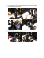
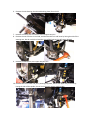
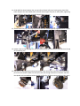
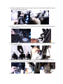
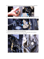
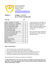
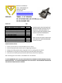
MAXTRAC SUSPENSION
4522 E. EISENHOWER CIR.
ANAHEIM, CA 92807
877-929-3016
WWW.MAXTRACSUSPENSION.COM
[email protected]
PRODUCT:
706840 - 4" LIFT SPINDLES
05-13 TACOMA 2WD, 06-13 FJ CRUISER 2WD
03-08 4-RUNNER 2WD
PARTS LIST
SPINDLE, TACOMA 4" LIFT, DRIVER
SPINDLE, TACOMA 4" LIFT, PASSENGER
5/8-11 X 3-1/4 HEX BOLT, GRD 8
5/8-11 STOVER LOCKNUT, GRD 8
5/8 FLAT WASHER, SAE, GRD 8
1/4" ADEL/LOOP CLAMP
5/16" ADEL/LOOP CLAMP
1/4-20 X 1-1/4 HEX BOLT, GRD 5, ZINC
1/4-20 NYLON LOCKNUT, ZINC
1/4 SAE FLAT WASHER, ZINC
QTY
1
1
4
4
8
4
2
6
6
12
PLEASE DOUBLE CHECK THE PARTS LIST
BEFORE BEGINNING INSTALLATION, TO
ENSURE ALL PARTS ARE PRESENT, IF
THERE IS SOMETHING MISSING, PLEASE
CONTACT MAXTRAC IMMEDIATELY
877-929-3016
READ THE INSTRUCTIONS THOROUGHLY
AND COMPLETELY BEFORE BEGINNING
THE INSTALLATION.
PRIOR TO INSTALLATION:
1. Factory service manual is recommended to have on hand.
2. Secure and properly block vehicle prior to beginning installation
3. Always wear safety glasses when using power tools or working under the vehicle
4. Modifications to any part will void the warranty associated with that product.
5. Jack up front of vehicle, place jack stands under frame, behind front suspension.
After removing parts from vehicle, save hardware for reinstallation
IT IS RECOMMENDED THAT YOU HAVE YOUR VEHICLE’S ALIGNMENT CHECKED WHEN INSTALLING
NEW SUSPENSION. IT IS ALSO RECOMMENDED THAT YOU ADJUST YOUR HEADLIGHTS WHENEVER
YOUR VEHICLE’S RIDE HEIGHT IS ALTERED.
1. On level ground, using a floor jack, raise the front end of your Tacoma and place jack stands
under frame behind the front suspension.
2. Remove the brake line bracket that is attached to the spindle, and move out of the way.
3. Remove brake caliper, then support it, do not allow it to hang from the brake hose.
4. Remove brake rotor.
5. Remove the sway bar end link from the spindle.
6. Remove the unit bearing, then discard backing plate / dust shield.
7. Remove the cotter pins from the tie rod and upper ball joint.
8. Remove the nut from the tie-rod end, and then break the tie rod loose by hitting the side of the
steering arm, but do not hit the threads or tie rod/ball joint as this will cause damage!
9. Remove the ABS Sensor, then upper ball joint nut.
10. Remove bolts from lower ball joint / steering stop plate, then break upper ball joint loose by
hitting the side of the spindle, do not hit the thread, remove stock spindle.
11. Guide ABS line down between the new spindle and lower ball joint/ steering stop plate. Slide
lower ball joint into the double sheer mount & attach upper ball joint to new spindle, tightening
nut on ball joint, align cotter pin hole & install OEM cotter pin.
12. Attach lower ball joint / steering stop plate to the new spindle, tighten supplied 5/8”x3 ¼” bolts
13. Rotate outer tie rods 180 degrees, this will now allow you to install the tie rod ends from the top
of the steering arm.
14. Reinstall Unit Bearing without the backing plate / dust shield, then install the rotor and caliper
per earlier instructions. Make sure that your rotor has enough clearance on the back side near
the spindle, we’ve manufactured the spindle to allow for all OEM, and some aftermarket rotors.
15. Remove the ABS line from the clip on the upper control arm, then remove the ABS line from the
clip on the back of the shock tower.
16. Remove bracket from upper control arm and discard, then remove ABS bracket from brake line
bracket and discard
17. Bend the tab on the brake line bracket, then attach brake line bracket to the new spindle using
the supplied hardware.
18. Remove stock brake line at the frame & caliper, then install new one. We suggest installing on
frame side first, to let fluid bleed through the new line, then attach on caliper side.
19. Tighten the new brake lines, per reversing the above steps.
20. Add more ‘bend’ to the brake line retainer clip to create more tension on the new brake line.
21. Remove the ABS line from behind the shock tower. Use supplied adell clamp to guide line across
the Upper Control Arm, do the same with the clamps on the spindle using supplied bolts.
22. Tighten ABS sensor below the lower ball joint. Reinstall cotter pin to the upper ball joint and tie
rod. See below for suggested brake line and ABS routing.
23. Manipulate the extra tab on the brake line bracket, either by bending it out of the way to
prevent contact on the sway bar at full turn, or cutting it off.