1
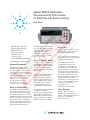
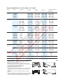
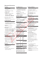
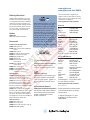
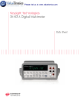
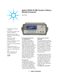
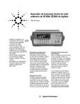
Test Equipment Solutions Datasheet
Test Equipment Solutions Ltd specialise in the second user sale, rental and distribution of
quality test & measurement (T&M) equipment. We stock all major equipment types such as
spectrum analyzers, signal generators, oscilloscopes, power meters, logic analysers etc from
all the major suppliers such as Agilent, Tektronix, Anritsu and Rohde & Schwarz.
We are focused at the professional end of the marketplace, primarily working with customers
for whom high performance, quality and service are key, whilst realising the cost savings that
second user equipment offers. As such, we fully test & refurbish equipment in our in-house,
traceable Lab. Items are supplied with manuals, accessories and typically a full no-quibble 2
year warranty. Our staff have extensive backgrounds in T&M, totalling over 150 years of
combined experience, which enables us to deliver industry-leading service and support. We
endeavour to be customer focused in every way right down to the detail, such as offering free
delivery on sales, covering the cost of warranty returns BOTH ways (plus supplying a loan
unit, if available) and supplying a free business tool with every order.
As well as the headline benefit of cost saving, second user offers shorter lead times, higher
reliability and multivendor solutions. Rental, of course, is ideal for shorter term needs and
offers fast delivery, flexibility, try-before-you-buy, zero capital expenditure, lower risk and off
balance sheet accounting. Both second user and rental improve the key business measure of
Return On Capital Employed.
We are based near Heathrow Airport in the UK from where we supply test equipment
worldwide. Our facility incorporates Sales, Support, Admin, Logistics and our own in-house
Lab.
All products supplied by Test Equipment Solutions include:
- No-quibble parts & labour warranty (we provide transport for UK mainland addresses).
- Free loan equipment during warranty repair, if available.
- Full electrical, mechanical and safety refurbishment in our in-house Lab.
- Certificate of Conformance (calibration available on request).
- Manuals and accessories required for normal operation.
- Free insured delivery to your UK mainland address (sales).
- Support from our team of seasoned Test & Measurement engineers.
- ISO9001 quality assurance.
Test equipment Solutions Ltd
Unit 8 Elder Way
Waterside Drive
Langley
Berkshire
SL3 6EP
T: +44 (0)1753 596000
F: +44 (0)1753 596001
Email: [email protected]
Web: www.TestEquipmentHQ.com
Agilent 34401A Multimeter
Uncompromising Performance
for Benchtop and System Testing
Data Sheet
• Measure up to 1000 volts
with 6 ½ digits resolution
• 0.0015% basic dcV
accuracy (24 hour)
• 0.06% basic acV
accuracy (1 year)
• 3 Hz to 300 kHz ac bandwidth
• 1000 readings/s direct to GPIB
Superior Performance
The Agilent Technologies 34401A
multimeter gives you the performance
you need for fast, accurate bench and
system testing. The 34401A provides a
combination of resolution, accuracy and
speed that rivals DMMs costing many
times more. 61/2 digits of resolution,
0.0015% basic 24-hr dcV accuracy
and 1,000 readings/s direct to
GPIB assure you of results that
are accurate, fast, and repeatable.
Use It on Your Benchtop
The 34401A was designed with your
bench needs in mind. Functions commonly associated with bench operation,
like continuity and diode test, are built in.
A Null feature allows you to remove lead
resistance and other fixed offsets in your
measurements. Other capabilities like
min/max/avg readouts and direct dB
and dBm measurements make checkout
with the 34401A faster and easier.
The 34401A gives you the ability to
store up to 512 readings in internal
memory. For trouble-shooting, a
reading hold feature lets you
concentrate on placing your test
leads without having to constantly
glance at the display.
Use It for Systems Testing
For systems use, the 34401A gives
you faster bus throughput than any
other DMM in its class. The 34401A
can send up to 1,000 readings/s
directly across GPIB in user-friendly
ASCII format.
You also get both GPIB and RS-232
interfaces as standard features.
Voltmeter Complete and External
Trigger signals are provided so you
can synchronize to other instruments
in your test system. In addition, a
TTL output indicates Pass/Fail
results when limit testing is used.
To ensure both forward and backward
compatibility, the 34401A
includes three command languages
(SCPI, Agilent 3478A and Fluke
8840A /42A), so you don’t have to
rewrite your existing test software. An
optional rack mount kit is available.
Easy to Use
Commonly accessed attributes, such as
functions, ranges, and resolution are
selected with a single button press.
Advanced features are available using
menu functions that let you optimize the
34401A for your applications.
The included Agilent IntuiLink
software allows you to put your
captured data to work easily, using
PC applications such as Microsoft
Excel® or Word® to analyze, interpret,
display, print, and document the data
you get from the 34401A. You can specify the meter setup and take a single
reading or log data to the Excel spreadsheet in specified time intervals.
Program-mers can use ActiveX components to control the DMM using SCPI
commands. To find out more
about IntuiLink, visit
www.agilent.com/find/intuilink
1-Year Warranty
With your 34401A, you get full
documentation, a high-quality test
lead set, calibration certificate with test
data, and a 1-year warranty,
all for one low price.
Accuracy Specifications ± (% of reading + % of range)1
Function
Range 3
DC voltage
100.0000 mV
1.000000 V
10.00000 V
100.0000 V
1000.000 V
True rms
AC voltage4
100.0000 mV
1.000000 V
to 750.000 V
Frequency,
etc.
24 Hour 2
23°C ±1°C
90 Day
23°C ±5°C
1 Year
23°C ±5°C
Temperature Coefficient
0°C – 18°C
28°C – 55°C
0.0030 + 0.0030
0.0020 + 0.0006
0.0015 + 0.0004
0.0020 + 0.0006
0.0020 + 0.0006
0.0040 + 0.0035
0.0030 + 0.0007
0.0020 + 0.0005
0.0035 + 0.0006
0.0035 + 0.0010
0.0050 + 0.0035
0.0040 + 0.0007
0.0035 + 0.0005
0.0045 + 0.0006
0.0045 + 0.0010
0.0005 + 0.0005
0.0005 + 0.0001
0.0005 + 0.0001
0.0005 + 0.0001
0.0005 + 0.0001
3 Hz – 5 Hz
5 Hz – 10 Hz
10 Hz – 20 kHz
20 kHz – 50 kHz
50 kHz – 100 kHz
100 kHz – 300 kHz6
1.00 + 0.03
0.35 + 0.03
0.04 + 0.03
0.10 + 0.05
0.55 + 0.08
4.00 + 0.50
1.00 + 0.04
0.35 + 0.04
0.05 + 0.04
0.11 + 0.05
0.60 + 0.08
4.00 + 0.50
1.00 + 0.04
0.35 + 0.04
0.06 + 0.04
0.12 + 0.05
0.60 + 0.08
4.00 + 0.50
0.100 + 0.004
0.035 + 0.004
0.005 + 0.004
0.011 + 0.005
0.060 + 0.008
0.20 + 0.02
3 Hz – 5 Hz
5 Hz –10 Hz
10 Hz – 20 kHz
20 kHz – 50 kHz
50 kHz – 100 kHz 5
100 kHz – 300 kHz 6
1.00 + 0.02
0.35 + 0.02
0.04 + 0.02
0.10 + 0.04
0.55 + 0.08
4.00 + 0.50
1.00 + 0.03
0.35 + 0.03
0.05 + 0.03
0.11 + 0.05
0.60 + 0.08
4.00 + 0.50
1.00 + 0.03
0.35 + 0.03
0.06 + 0.03
0.12 + 0.04
0.60 + 0.08
4.00 + 0.50
0.100 + 0.003
0.035 + 0.003
0.005 + 0.003
0.011 + 0.005
0.060 + 0.008
0.20 + 0.02
0.0030 + 0.0030
0.0020 + 0.0005
0.0020 + 0.0005
0.0020 + 0.0005
0.002 + 0.001
0.015 + 0.001
0.300 + 0.010
0.008 + 0.004
0.008 + 0.001
0.008 + 0.001
0.008 + 0.001
0.008 + 0.001
0.020 + 0.001
0.800 + 0.010
0.010 + 0.004
0.010 + 0.001
0.010 + 0.001
0.010 + 0.001
0.010 + 0.001
0.040 + 0.001
0.800 + 0.010
0.0006 + 0.0005
0.0006 + 0.0001
0.0006 + 0.0001
0.0006 + 0.0001
0.0010 + 0.0002
0.0030 + 0.0004
0.1500 + 0.0002
0.005 + 0.010
0.010 + 0.004
0.050 + 0.006
0.100 + 0.020
0.030 + 0.020
0.030 + 0.005
0.080 + 0.010
0.120 + 0.020
0.050 + 0.020
0.050 + 0.005
0.100 + 0.010
0.120 + 0.020
0.0020 + 0.0020
0.0020 + 0.0005
0.0050 + 0.0010
0.005 + 0.0020
Resistance 7
100.0000 Ω
1.000000 kΩ
10.00000 kΩ
100.0000 kΩ
1.000000 MΩ
10.00000 MΩ
100.0000 MΩ
DC current
10.00000 mA
100.0000 mA
1.000000 A
3.00000 A
True rms
AC current 4
1.000000 A
3 Hz – 5 Hz
5 Hz – 10 Hz
10 Hz – 5 kHz
1.00 + 0.04
0.30 + 0.04
0.10 + 0.04
1.00 + 0.04
0.30 + 0.04
0.10 + 0.04
1.00 + 0.04
0.30 + 0.04
0.10 + 0.04
0.100 + 0.006
0.035 + 0.006
0.015 + 0.006
3.00000 A
3 Hz – 5 Hz
5 Hz – 10 Hz
10 Hz – 5 kHz
1.10 + 0.06
0.35 + 0.06
0.15 + 0.06
1.10 + 0.06
0.35 + 0.06
0.15 + 0.06
1.10 + 0.06
0.35 + 0.06
0.15 + 0.06
0.100 + 0.006
0.035 + 0.006
0.015 + 0.006
Frequency
or period 8
100 mV to
750 V
3 Hz – 5 Hz
5 Hz – 10 Hz
10 Hz – 40 Hz
40 Hz – 300 kHz
0.10
0.05
0.03
0.006
0.10
0.05
0.03
0.01
0.10
0.05
0.03
0.01
0.005
0.005
0.001
0.001
Continuity
1000.0 Ω
1 mA test current
0.002 + 0.030
0.008 + 0.030
0.010 + 0.030
0.001 + 0.002
Diode test 9
1.0000 V
1 mA test current
0.002 + 0.010
0.008 + 0.020
0.010 + 0.020
0.001 + 0.002
1 mA Current Source
1 mA
100 µA
10 µA
5.0 µA
500 nA
500 nA || 10 MΩ
< 0.1 V Burden Voltage
< 0.6 V
< 1.0 V
< 2.0 V
1. Specifications are for 1 hr warm-up and 6½ digits, slow ac filter.
2. Relative to calibration standards.
3. 20% over range on all ranges except 1000 Vdc and 750 Vac ranges.
4. For sinewave input > 5% of range. For inputs from 1% to 5% of range
and < 50 kHz, add 0.1% of range additional error.
5. 750 V range limited to 100 kHz or 8 x 10⁷ Volt-Hz.
6. Typically 30% of reading error at 1 MHz.
7. Specifications are for 4-wire ohms function or 2-wire ohms using Math
Null. Without Math Null, add 0.2 Ω additional error in 2-wire ohms
function.
8. Input >100 mV. For 10 mV to 100 mV inputs multiply % of reading
error x10.
9. Accuracy specifications are for the voltage measured at the input terminals only. 1 mA test current is typical. Variation in the current source will
create some variation in the voltage drop across a diode junction.
103.6 mm
254.4 mm
374.0 mm
88.5 mm
212.6 mm
2
348.3 mm
Measurement Characteristics
DC Voltage
True RMS AC Current
Triggering and Memory
Measurement Method:
Continuously integrating multi-slope III
A-D converter
Measurement Method:
Directly coupled to the fuse and shunt.
ac coupled true rms measurement
(measures the ac component only).
Reading HOLD Sensitivity:
10%, 1%, 0.1%, or 0.01% of range
A-D Linearity: 0.0002% of reading +
0.0001% of range
Input Resistance:
10 MΩ or 0.1 V, 1 V, 10 V ranges:
Selectable > 10,000 MΩ
100 V, 1000 V ranges: 10 MΩ ±1%
Input Bias Current: < 30 pA at 25°C
Input Protection: 1000 V all ranges
dcV:dcV ratio accuracy:
Vinput Accuracy + Vrelevance Accuracy
Shunt Resistance:
0.1 Ω for 1 A and 3 A ranges
Input Protection:
Externally accessible 3 A 250 V fuse
Internal 7 A 250 V fuse
Frequency and Period
Measurement Method:
Reciprocal counting technique
Voltage Ranges:
Same as ac voltage function
True RMS AC Voltage
Gate Time: 1 s, 100 ms, or 10 ms
Measurement Method:
AC-coupled true rms-measures the ac
component of the input with up to 400
Vdc of bias on any range.
Continuity/Diode
Crest Factor:
Maximum of 5:1 at full scale.
Additional Crest Factor errors
(non-sinewave):
Crest factor 1-2: 0.05% of reading
Crest factor 2-3: 0.15% of reading
Crest factor 3-4: 0.30% of reading
Crest factor 4-5: 0.40% of reading
Input Impedance:
1 MΩ ± 2% in parallel with 100 pF
Input Protection: 750 Vrms all ranges
Resistance
Measurement Method:
Selectable 4-wire or 2-wire Ohms.
Current source referenced to LO input.
Maximum Lead Resistance (4-wire):
10% of range per lead for 100 Ω, 1 kΩ
ranges.
1 kΩ per lead on all other ranges.
Response Time:
300 samples/s with audible tone
Continuity Threshold:
Selectable from 1 Ω to 1000 Ω
Measurement Noise Rejection 60 (50) Hz1
dc CMRR: 140 dB
ac CMRR: 70 dB
Integration Time and
Normal Mode Rejection2
100 plc/1.67 s (2 s): 60 dB3
10 plc/167 ms (200 ms): 60 dB3
1 plc/16.7 ms (20 ms): 60 dB
<1 plc/3 ms or 800 µs): 0 dB
Operating Characteristics 4
Function
Digits
dcV, dcl, and 6 ½
Resistance
6½
5½
5½
4½
acV, acl
Input Protection: 1000 V all ranges
DC Current
Shunt Resistance:
5 Ω for 10 mA, 100 mA
0.1 Ω for 1 A, 3 A
Input Protection:
Externally accessible 3 A 250 V fuse
Internal 7 A 250 V fuse
Frequency
or Period
Reading/s
0.6 (0.5)
6 (5)
60 (50)
300
1000
6½
6½
6½
6½
0.15 slow (3 Hz)
1 medium (20 Hz)
10 fast (200 Hz)5
50
6½
5½
4½
1
9.8
80
Frequency and Period
Configuration rates:
Autorange rate (dc Volts):
ASCII readings to RS-232:
ASCII readings to RS-232:
Maximum internal trig rate:
Max. ext trig. rate to mem:
3
26/s to 50/s
>30/s
55/s
1000/s
1000/s
1000/s
Samples/Trigger: 1 to 50,000
Trigger Delay: 0 to 3600 s: 10 µs step
size
External Trigger Delay: < 1 ms
External Trigger Jitter: < 500 µs
Memory: 512 readings
Math Functions
NULL, min/max/average, dBm, dB, limit
test (with TTL output)
Standard Programming Languages
SCPI (IEEE-488.2), Agilent 3478A,
Fluke 8840A/42A
Accessories Included
Test lead kit with probe, alligator
and grabber attachments
Operating manual, service manual,
test report and power cord
General Specifications
Power Supply:
100 V/120 V/220 V/240 V ±10%
Power Line Frequency:
45 Hz to 66 Hz and 360 Hz to 440 Hz,
Automatically sensed at power-on
Power Consumption: 25 VA peak
(10 W average)
Operating Environment:
Full accuracy for 0°C to 55°C,
Full accuracy to 80% R.H. at 40°C
Storage Temperature: -40°C to 70°C
Weight: 3.6 kg (8.0 lbs)
Safety: Designed to CSA, UL-1244,
IEC-348
RFI and ESD: MIL-461C, FTZ 1046, FCC
Vibration & Shock: MIL-T-28800E, Type
III, Class 5 (sine only)
Warranty: 1 year
1. For 1 kΩ unbalanced in LO lead,
± 500 V peak maximum.
2. For power line frequency ± 0.1%.
3. For power line frequency ± 0.1% use 40 dB
or ± 3% use 30 dB.
4. Reading speeds for 60 Hz and (50 Hz)
operation.
5. Maximum useful limit with default settling
delays defeated.
6. Speeds are for 4½ digits, delay 0, auto-zero
and display OFF.
www.agilent.com
www.agilent.com/find/34401A
Ordering Information
Agilent 34401A multimeter accessories
included: Test lead kit with probe, alligator, and grabber attachments, calibration
certificate, test report, and power cord.
Also includes CD with: IntuiLink software,
IVI and VXI PnP drivers, Quick start tutorial, user's guide, command quick reference, service guide, and data sheet.
Options
34401A-A6J
ANSI Z540 compliant calibration
Accessories
For more information on Agilent Technologies’ products, applications or services,
please contact your local Agilent office. The
complete list is available at:
Agilent Advantage Services is committed
to your success throughout your equipment’s lifetime. To keep you competitive,
we continually invest in tools and processes that speed up calibration and
repair and reduce your cost of ownership.
You can also use Infoline Web Services to
manage equipment and services more
effectively. By sharing our measurement
and service expertise, we help you create
the products that change our world.
Probes/Leads/Clip Accessories
11059A Kelvin probe set
11060A Surface mount device (SMD) test
probes
11062A Kelvin clip set
34133A Precision electronic test leads
34134A DC coupled current probe
34136A High voltage probe
34138A Test lead set
34171B Input terminal connector
(sold in pairs)
34172B Input calibration short
(sold in pairs)
34330A 30 A current shunt
E2308A 5 k thermistor probe
Y1133A Low-thermal external digital
multimeter scanning kit
www.agilent.com/find/advantageservices
Rack Mount Kits
34190A Rackmount kit: designed for use
with only one instrument, mounted on
either the left or the right side of the rack.
34191A 2U Dual flange kit: secures the
instrument to the front of the rack. This
kit can be used with the 34194A dual lock
link kit to mount two half-width, 2U height
instruments side-by side.
34194A Dual lock link kit: recommended
for side-by-side combinations and includes
links for instruments of different depths.
This kit can be used with the 34191A 2U
dual flange kit to mount two half-width, 2U
height instruments side-by-side.
www.lxistandard.org
LAN eXtensions for Instruments puts
the power of Ethernet and the Web
inside your test systems. Agilent is a
founding member of the LXI consortium.
Other Accessories
34131A Hard transit case
34161A Accessory pouch
34398A RS-232 cable, 9 pin (f) to 9 pin (f)
E5810A LAN/GPIB gateway
www.agilent.com/find/contactus
Americas
Canada
Brazil
Mexico
United States
(877) 894 4414
(11) 4197 3600
01800 5064 800
(800) 829 4444
Asia Pacific
Australia
China
Hong Kong
India
Japan
Korea
Malaysia
Singapore
Taiwan
Other AP Countries
1 800 629 485
800 810 0189
800 938 693
1 800 112 929
0120 (421) 345
080 769 0800
1 800 888 848
1 800 375 8100
0800 047 866
(65) 375 8100
www.agilent.com/quality
Agilent Email Updates
www.agilent.com/find/emailupdates
Get the latest information on the
products and applications you select.
Agilent Channel Partners
www.agilent.com/find/channelpartners
Get the best of both worlds: Agilent’s
measurement expertise and product
breadth, combined with channel
partner convenience.
Europe & Middle East
Belgium
32 (0) 2 404 93 40
Denmark
45 45 80 12 15
Finland
358 (0) 10 855 2100
France
0825 010 700*
*0.125 €/minute
Germany
Ireland
Israel
Italy
Netherlands
Spain
Sweden
United Kingdom
49 (0) 7031 464 6333
1890 924 204
972-3-9288-504/544
39 02 92 60 8484
31 (0) 20 547 2111
34 (91) 631 3300
0200-88 22 55
44 (0) 118 927 6201
For other unlisted countries:
www.agilent.com/find/contactus
Revised: January 6, 2012
Product specifications and descriptions
in this document subject to change
without notice.
© Agilent Technologies, Inc. 2012
Published in USA, April 24, 2012
5968-0162EN