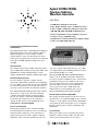
1
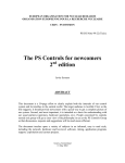
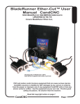
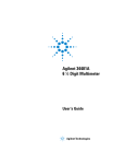
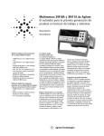
Rév A - Edition 2 - 24/27 9, rue Georges Besse BP 47 78330 FONTENAY-LE-FLEURY France Tél. : 33 (0)1 30 58 90 09 Fax : 33 (0)1 30 58 21 33 www.adas.fr BANC MOBILE DE CONTROLE Documentation S.A.S au capital de 305 000 € RCS Versailles B 325 070 746 Siret 325 070 746 00046 APE 2651B TVA FR 52325 070 746 TRACEABILITY FORM DOCUMENT FOLLOW-UP Title: BMC Titre : Documentation française Edition1: (Document creation - Création du document) Written by D. PIMONT on Revised by Ph. DUTIN on Approved by B. THOUËNON on Warning: Unless otherwise stated, this revision overwrites the previous one, which must be destroyed, along with any copies given to your collaborators. 24/27 Visa 24/27 Visa 24/27 Visa Avertissement : En l’absence d’indication contraire, cette nouvelle édition annule et remplace l’édition précédente qui doit être détruite, ainsi que les copies faites à vos collaborateurs. Edition Nature of the modifications (key words) Written Revised/Approved Edition Nature des évolutions (mots clés) Rédigé Revu/Approuvé 2 3 4 5 6 DOCUMENT ARCHIVED DOCUMENT ARCHIVE Yes No by by on on Visa Visa by by on on Visa Visa by by on on Visa Visa by by on on Visa Visa by by on on Visa Visa on Δ ed. .. [ ] = Document input/output (Entrée/sortie modification de la documentation) # ed. .. [ ] = Board new function input/output (Entrée/sortie nouvelle fonctionnalité du produit) DSQ - 4.5.a - Indice F - 98/41 T.S.V.P. BMC – BANC MOBILE DE CONTROLE – Rev. A – Edition 2 – 24/27 1 NOTES : BMC – BANC MOBILE DE CONTROLE – Rev. A – Edition 2 – 24/27 2 BMC SOMMAIRE Chapitre A Présentation......................................... 4 A.1. Câblage et interconnexion ..................................................... 4 Chapitre B Constitution du banc........................... 5 B.1. Coffret ...................................................................................... 6 B.2. Rack VME................................................................................. 7 B.2.1. Bus VME ...................................................................... 7 B.2.2. Alimentations................................................................ 8 B.2.3. Face avant.................................................................... 8 B.3. Multimètre ................................................................................ 9 B.4. Générateur AC....................................................................... 10 B.5. Générateur DC....................................................................... 11 B.6. Multiplexeur ........................................................................... 12 B.7. Passerelle VME / VME........................................................... 13 B.8. Unité centrale ........................................................................ 14 B.9. PC portable ............................................................................ 14 B.10. Carte prolongateur................................................................ 15 Chapitre C Mise en oeuvre................................... 16 C.1. Installation ............................................................................. 16 C.2. Raccordements ..................................................................... 16 C.3. Mise sous tension ................................................................. 16 Annexe ............................................................ 17 DOCUMENTATIONS PRODUITS ............................................................. 17 BMC – BANC MOBILE DE CONTROLE – Rev. A – Edition 2 – 24/27 3 Chapitre A Présentation Le Banc Mobile de Contrôle permet le test et la calibration des équipements de mesures réalisés à partir des produits de l’offre ADAS Electronique (borniers conditionneurs, cartes d’acquisitions). Sa conception a été dictée par les critères suivants : Banc mobile pouvant être utilisé sur le site opérationnel Utilisation de produits standards dans sa conception pour assurer une maintenance aisée et une pérennité de fonctionnement Structure évolutive pour le test de nouveaux produits Très bonnes caractéristiques métrologiques en étant au plus près des conditions opérationnelles de fonctionnement Mise en œuvre et utilisation simple afin d’obtenir des résultats rapides et clairs A.1. Câblage et interconnexion Voir documentation « BMC Mise en Œuvre ». BMC – BANC MOBILE DE CONTROLE – Rev. A – Edition 2 – 24/27 4 Chapitre B Constitution du banc Les plans ci-après illustrent la structure retenue par le BMC. Les sous-ensembles fonctionnels font l’objet d’une documentation spécifique. Le lecteur trouvera dans chaque sous-chapitre les particularismes éventuels et les informations complémentaires attachées au Banc Mobile de Contrôle. BMC – BANC MOBILE DE CONTROLE – Rev. A – Edition 2 – 24/27 5 BANC DE TEST VME 1 CALCULATEUR VME 2 TEST VP2 10x/02 PILOTAGE CPU ICVMUX ICV701 RV900 TEST TEST TEST OU STIMULIS GENERATEUR EV900 MESURES MULTIMETRE CORDONS DE TESTS RV900 ICV150 ICV117 ICV196 ICV307 ICV306 ICV714 ICV712 RACK VME A TESTER AUTRE CORDONS DE TESTS RACK BCI A TESTER BCI310 BCI382 AUTRE CORDONS DE TESTS B.1. Coffret Comme nous l’avons vu, le BMC doit être opérationnel au plus près des équipements à contrôler. Pour cela, une structure de type transportable a été retenue. Un coffret étanche et muni d’amortisseurs a été choisi pour contenir l’ensemble de l’électronique. Coffret réf. : INCAS / KNURR Dimensions coffret fermé : Hauteur = 618mm Largeur = 534mm Profondeur = 710mm Poids = 64kg A l’arrière du coffret, une réglette de prises avec protection par différentiel 30mA est prévue pour la distribution du secteur aux différents sousensembles. >>>REMARQUES : Le poids nécessite la présence de deux personnes pour le transport Les équipements en interne sont de classe métrologique et un soin particulier doit être pris lors du transport BMC – BANC MOBILE DE CONTROLE – Rev. A – Edition 2 – 24/27 6 B.2. Rack VME Référence : CCV04/04/BMC Le rack VME est issu d’une structure de base du CCV07. Pour cette application, des modifications ont été apportées pour répondre aux exigences techniques du BMC. B.2.1. Bus VME Le rack VME possède 2 bus VME distincts de 4 slots chacun : Un bus « système » de base qui contient : 1 x CPU 1 x ICV 701 1 x carte ICV MUX 1 x émetteur EV900 de la passerelle PVV 900 Ce bus est donc complet Un bus VME pour le test des cartes VME qui contient : 1 x récepteur RV900 de la passerelle PVV 900 Les 3 autres slots sont libres pour recevoir des cartes VME à tester >>>ATTENTION : Les 2 slots du haut possèdent un bus « P2 » ADAS : VP2/10x/02 pour la liaison locale entre o une ICV 10x et les cartes coupleurs gérées par cette carte ICV 118, ICV 120, ICV 122, ICV 124, ICV 128, ICV 138, ICV 140 o une ICV 150 vers ICV 110, ICV 117. BMC – BANC MOBILE DE CONTROLE – Rev. A – Edition 2 – 24/27 7 B.2.2. Alimentations Le CCV04/04/BMC est équipé de deux alimentations distinctes : Une alimentation de la partie « système » du rack (VME 4 slots du bas) Celle-ci est mise en route par le marche/arrêt principal à clé Une alimentation de la partie « test » du rack (VME 4 slots du haut) Celle-ci possède son propre marche/arrêt Ainsi il est possible de tester plusieurs cartes sans couper la partie « système » ce qui évite un « Boot » à chaque mise sous tension. Le Marche/arrêt principal coupe lui l’intégralité du châssis. B.2.3. Face avant La face avant du CCV04/04/BMC comprend : Les indicateurs habituels des racks VME Un bandeau spécifique du BMC avec : Une prise type « D » 50pts femelle vers les produits à tester (en fonction de câble spécifique à chaque produit) Une prise type µD 68pts pour l’utilisation du récepteur VME (RV900) dans un rack VME externe (cas du test des cartes dans leur positionnement opérationnel Une prise AUI Ethernet pour la liaison avec le PC portable qui gère le BMC >>>REMARQUES : Cette disposition a l’avantage de ne nécessiter que peu de câbles dans le mode opérationnel Lorsque l’on test des cartes en « local », la procédure est identique (les câbles utilisés sont les mêmes) BMC – BANC MOBILE DE CONTROLE – Rev. A – Edition 2 – 24/27 8 B.3. Multimètre Le multimètre utilisé est un AGILENT réf. : 34401A Le lecteur se reportera aux documentations constructeur fournies en annexe. Le multimètre est utilisé pour : La mesure des tensions AC/DC La mesure des courants en DC La mesure des résistances (une conversion temp = fR est faite par logiciel pour les PT100/PT1000) Les autotests de banc Le branchement s’effectue à l’arrière du multimètre (on veillera à ce que le bouton « rear » soit enfoncé). La liaison avec la carte CPU du BMC s’effectue par une RS232. BMC – BANC MOBILE DE CONTROLE – Rev. A – Edition 2 – 24/27 9 B.4. Générateur AC Le générateur utilisé est un AGILENT réf. : 33220 Le lecteur se reportera aux documentations constructeur fournies en annexe. Le générateur est utilisé pour : Le contrôle des bandes passantes des modules sous test Le contrôle des cartes de comptage Le branchement s’effectue en face avant. La liaison avec la carte CPU du BMC s’effectue par une liaison USB. BMC – BANC MOBILE DE CONTROLE – Rev. A – Edition 2 – 24/27 10 B.5. Générateur DC La génération des tensions continues est assurée par une carte VME, réf. : ICV 701 ADAS Le lecteur se reportera aux documentations fournies en annexe. La carte est utilisée pour : La génération des tensions continues de ± 10V à quelques µV La génération de courants Le branchement s’effectue en face avant de la carte. L’ICV 701 est pilotée directement par la CPU via le Bus VME BMC – BANC MOBILE DE CONTROLE – Rev. A – Edition 2 – 24/27 11 B.6. Multiplexeur Le banc permet, après raccordement, le test de : 8 voies conditionnées 16 voies de type entrées/sorties différentielles La fonction multiplexage est assurée par une carte VME : ICV MUX ADAS Voir documentation en annexe. Cette carte reçoit : Le générateur DC Le générateur AC Une boîte à décades résistives (option) Elle dirige les ressources vers : Les voies à tester via un câble spécifique au produit sous test Un multimètre qui indique les résultats obtenus Elle est pilotée par la carte CPU sur le VME. BMC – BANC MOBILE DE CONTROLE – Rev. A – Edition 2 – 24/27 12 B.7. Passerelle VME / VME Le BMC utilise une passerelle VME / VME PVV 900 ADAS Voir documentation en annexe. Cette technique permet : En utilisation interne au banc de dissocier la partie « système » de la partie sous test. Ainsi il n’y a pas d’ingérance de la (ou des) carte(s) sous test sur le système. De plus, l’utilisateur peut couper l’alimentation de la zone « test » sans avoir à recharger le système d’exploitation En utilisation externe La passerelle peut être introduite dans un slot libre d’un rack VME et procéder aux tests des cartes à leur adresse et emplacement physique. Ainsi le contrôle s’effectue sans intervention sur les cartes à tester BMC – BANC MOBILE DE CONTROLE – Rev. A – Edition 2 – 24/27 13 B.8. Unité centrale Le châssis VME est géré par une carte CPU PENTIUM sous le système d’exploitation LINUX. La carte est un produit CONCURRENT TECHNOLOGY réf. : VP CP1/P (Voir documentation jointe). Cette carte assure : Les liaisons avec le voltmètre via une RS232 La liaison avec le générateur via une prise Ethernet La liaison avec le PC portable via une prise Ethernet AUI L’interface VME des cartes ICV 701, ICV MUX et PVV 900 Un disque dur IDE contient le code LINUX et les logiciels de tests des produits. B.9. PC portable L’opérateur dialogue avec le BMC via un PC portable. Le modèle retenu est un DELL >>>NB : Un switch Ethernet est présent à l’intérieur du BMC pour assurer les différentes commutations sur ce réseau. BMC – BANC MOBILE DE CONTROLE – Rev. A – Edition 2 – 24/27 14 B.10. Carte prolongatrice Pour le test et la calibration des borniers BCI, une carte prolongatrice est prévue : Réf. : BCI PROL ADAS La documentation de ce produit est donnée en annexe. BMC – BANC MOBILE DE CONTROLE – Rev. A – Edition 2 – 24/27 15 Chapitre C Mise en oeuvre C.1. Installation Avant toute chose, l’opérateur prendra connaissance du document consultable en ligne sur notre site internet www.adas.fr Cliquez sur l’icône : GENERAL INSTRUCTIONS FOR IMPLEMENTING ADAS PRODUCTS INSTRUCTIONS GENERALES DE MISE EN OEUVRE DES PRODUITS ADAS C.2. Raccordements L’utilisateur veillera au bon raccordement des câbles du banc lui-même et au niveau du raccordement avec le (ou les) équipement(s) à tester. C.3. Mise sous tension La mise sous tension s’effectue par le M/A différentiel situé à l’arrière du BMC Les équipements doivent être sur « ON » Pour atteindre les caractéristiques métrologiques un temps d’attente de 1/2h doit avoir lieu pour la stabilisation thermique des équipements. BMC – BANC MOBILE DE CONTROLE – Rev. A – Edition 2 – 24/27 16 Annexe DOCUMENTATIONS PRODUITS Les constituants principaux du BMC font l’objet d’une documentation spécifique « constructeur » fournie en complément de cette documentation : Multimètre Générateur AC ICV 701 ICV MUX PVV 900 CPU Pentium BCI PROL BMC – BANC MOBILE DE CONTROLE – Rev. A – Edition 2 – 24/27 17 Agilent 34401A Multimeter Uncompromising Performance for Benchtop and System Testing Product Overview • Measure up to 1000 volts with 6 1/2 digits resolution • 0.0015% basic dcV accuracy (24 hour) • 0.06% basic acV accuracy (1 year) The 34401A gives you the ability to store up to 512 readings in internal memory. For trouble-shooting, a reading hold feature lets you concentrate on placing your test leads without having to constantly glance at the display. • 3Hz to 300kHz ac bandwidth • 1000 readings/sec. direct to GPIB Superior performance The Agilent Technologies 34401A multimeter gives you the performance you need for fast, accurate bench and system testing. The 34401A provides a combination of resolution, accuracy and speed that rivals DMMs costing many times more. 6 1/2-digits of resolution, 0.0015% basic 24-hr dcV accuracy and 1,000 readings/sec direct to GPIB assure you of results that are accurate, fast, and repeatable. Use it on your benchtop The 34401A was designed with your bench needs in mind. Functions commonly associated with bench operation, like continuity and diode test, are built in. A Null feature allows you to remove lead resistance and other fixed offsets in your measurements. Other capabilities like min/max/avg readouts and direct dB and dBm measurements make checkout with the 34401A faster and easier. Use it for systems testing For systems use, the 34401A gives you faster bus throughput than any other DMM in its class. The 34401A can send up to 1,000 readings/sec directly across GPIB in user-friendly ASCII format. You also get both GPIB and RS-232 interfaces as standard features. Voltmeter Complete and External Trigger signals are provided so you can synchronize to other instruments in your test system. In addition, a TTL output indicates Pass/Fail results when limit testing is used. To ensure both forward and backward compatibility, the 34401A includes three command languages (SCPI, Agilent 3478A and Fluke 8840A /42A), so you don’t have to rewrite your existing test software. An optional rack mount kit is available. Easy to use Commonly accessed attributes, such as functions, ranges, and resolution are selected with a single button press. Advanced features are available using menu functions that let you optimize the 34401A for your applications. The included Agilent IntuiLink software allows you to put your captured data to work easily, using PC applications such as Microsoft Excel® or Word® to analyze, interpret, display, print, and document the data you get from the 34401A. You can specify the meter setup and take a single reading or log data to the Excel spreadsheet in specified time intervals. Programmers can use ActiveX components to control the DMM using SCPI commands. To find out more about IntuiLink, visit www.agilent.com/find/intuilink The 34401A can also be used in conjunction with the 34812A BenchLink Meter software. This Windows-based program lets you configure and initiate measurements from your computer, and transfer results from your test instrument to your PC. 3-year warranty With your 34401A, you get full documentation, a high-quality test lead set, calibration certificate with test data, and a 3-year warranty, all for one low price. Accuracy Specifications ± (% of reading + % of range)[1] 24 Hour [2] 23°C ± 1°C 90 Day 23°C ± 5°C 1 Year 23°C ± 5°C Temperature Coefficient 0°C – 18°C 28°C – 55°C 0.0030 + 0.0030 0.0020 + 0.0006 0.0015 + 0.0004 0.0020 + 0.0006 0.0020 + 0.0006 0.0040 + 0.0035 0.0030 + 0.0007 0.0020 + 0.0005 0.0035 + 0.0006 0.0035 + 0.0010 0.0050 + 0.0035 0.0040 + 0.0007 0.0035 + 0.0005 0.0045 + 0.0006 0.0045 + 0.0010 0.0005 + 0.0005 0.0005 + 0.0001 0.0005 + 0.0001 0.0005 + 0.0001 0.0005 + 0.0001 3 Hz - 5 Hz 5 Hz - 10 Hz 10 Hz - 20 kHz 20 kHz - 50 kHz 50 kHz - 100 kHz 100 kHz - 300 kHz[6] 1.00 + 0.03 0.35 + 0.03 0.04 + 0.03 0.10 + 0.05 0.55 + 0.08 4.00 + 0.50 1.00 + 0.04 0.35 + 0.04 0.05 + 0.04 0.11 + 0.05 0.60 + 0.08 4.00 + 0.50 1.00 + 0.04 0.35 + 0.04 0.06 + 0.04 0.12 + 0.04 0.60 + 0.08 4.00 + 0.50 0.100 + 0.004 0.035 + 0.004 0.005 + 0.004 0.011 + 0.005 0.060 + 0.008 0.20 + 0.02 1.000000 V to 750.000 V 3 Hz - 5 Hz 5 Hz - 10 Hz 10 Hz - 20 kHz 20 kHz - 50 kHz 50 kHz - 100 kHz[5] 100 kHz - 300 kHz[6] 1.00 + 0.02 0.35 + 0.02 0.04 + 0.02 0.10 + 0.04 0.55 + 0.08 4.00 + 0.50 1.00 + 0.03 0.35 + 0.03 0.05 + 0.03 0.11 + 0.05 0.60 + 0.08 4.00 + 0.50 1.00 + 0.03 0.35 + 0.03 0.06 + 0.03 0.12 + 0.04 0.60 + 0.08 4.00 + 0.50 0.100 + 0.003 0.035 + 0.003 0.005 + 0.003 0.011 + 0.005 0.060 + 0.008 0.20 + 0.02 Resistance[7] 100.0000 Ω 1.000000 kΩ 10.00000 kΩ 100.0000 kΩ 1.000000 MΩ 10.00000 MΩ 100.0000 MΩ 1 mA Current Source 1 mA 100 µA 10 µA 5.0 µA 500 nA 500 nA || 10MΩ 0.0030 + 0.0030 0.0020 + 0.0005 0.0020 + 0.0005 0.0020 + 0.0005 0.002 + 0.001 0.015 + 0.001 0.300 + 0.010 0.008 + 0.004 0.008 + 0.001 0.008 + 0.001 0.008 + 0.001 0.008 + 0.001 0.020 + 0.001 0.800 + 0.010 0.010 + 0.004 0.010 + 0.001 0.010 + 0.001 0.010 + 0.001 0.010 + 0.001 0.040 + 0.001 0.800 + 0.010 0.0006 + 0.0005 0.0006 + 0.0001 0.0006 + 0.0001 0.0006 + 0.0001 0.0010 + 0.0002 0.0030 + 0.0004 0.1500 + 0.0002 dc Current 10.00000 mA 100.0000 mA 1.000000 A 3.00000 A <0.1 V Burden Voltage <0.6 V <1 V <2 V 0.005 + 0.010 0.010 + 0.004 0.050 + 0.006 0.100 + 0.020 0.030 + 0.020 0.030 + 0.005 0.080 + 0.010 0.120 + 0.020 0.050 + 0.020 0.050 + 0.005 0.100 + 0.010 0.120 + 0.020 0.002 + 0.0020 0.002 + 0.0005 0.005 + 0.0010 0.005 + 0.0020 True rms ac Current[4] 1.000000 A 3 Hz - 5 Hz 5 Hz - 10 Hz 10 Hz - 5 kHz 1.00 + 0.04 0.30 + 0.04 0.10 + 0.04 1.00 + 0.04 0.30 + 0.04 0.10 + 0.04 1.00 + 0.04 0.30 + 0.04 0.10 + 0.04 0.100 + 0.006 0.035 + 0.006 0.015 + 0.006 3.00000 A 3 Hz - 5 Hz 5 Hz - 10 Hz 10 Hz - 5 kHz 1.10 + 0.06 0.35 + 0.06 0.15 + 0.06 1.10 + 0.06 0.35 + 0.06 0.15 + 0.06 1.10 + 0.06 0.35 + 0.06 0.15 + 0.06 0.100 + 0.006 0.035 + 0.006 0.015 + 0.006 Frequency or Period[8] 100 mV to 750 V 3 Hz - 5 Hz 5 Hz - 10 Hz 10 Hz - 40 Hz 40 Hz - 300 kHz 0.10 0.05 0.03 0.006 0.10 0.05 0.03 0.01 0.10 0.05 0.03 0.01 0.005 0.005 0.001 0.001 Continuity 1000.0Ω 1mA Test Current 0.002 + 0.010 0.008 + 0.020 0.010 + 0.020 0.001 + 0.002 Diode Test 1.0000V 1mA Test Current 0.002 + 0.010 0.008 + 0.020 0.010 + 0.020 0.001 + 0.002 Frequency, etc. Function Range[3] dc Voltage 100.0000 mV 1.000000 V 10.00000 V 100.0000 V 1000.000 V True rms ac Voltage[4] 100.0000 mV 1 2 3 4 103.6 mm 254.4 mm 374.0 mm 5 6 7 8 88.5 mm 212.6 mm 2 348.3 mm Specifications are for 1hr warm-up and 6 1 ⁄ 2 digits, Slow ac filter. Relative to calibration standards. 20% over range on all ranges except 1000Vdc and 750Vac ranges. For sinewave input > 5% of range. For inputs from 1% to 5% of range and < 50kHz, add 0.1% of range additional error. 750V range limited to 100 kHz or 8 x10⁷ Volt-Hz. Typically 30% of reading error at 1MHz. Specifications are for 4- wire ohms function or 2-wire ohms using Math Null. Without Math Null, add 0.2 Ω additional error in 2-wire ohms function. Input >100 mV. For 10 mV inputs multiply % of reading error x10. Measurement Characteristics dc Voltage True rms ac Current System Speeds[6] Measurement Method Continuously Integrating Multi-slope III A-D Converter A-D Linearity 0.0002% of reading + 0.0001 % of range Input Resistance 0.1V, 1V,10 V ranges Selectable 10 MΩ or >10,000 MΩ 100 V, 1000 V ranges 10 MΩ ± 1% Input Bias Current < 30pA at 25° C Input Protection 1000 V all ranges dcV:dcV Ratio Accuracy Vinput Accuracy + Vreference Accuracy Measurement Method Direct coupled to the fuse and shunt. ac coupled True rms measurement (measures the ac component only). Shunt Resistance 0.1 Ω for 1 A and 3 A ranges Input Protection ExternalIy accessible 3 A 250 V Fuse Internal 7 A 250 V Fuse Configuration Rates 26/s to 50/s Autorange Rate >30/s (dc Volts) ASCII readings to RS-232 55/s ASCII readings to GPIB 1000/s Maximum Internal Trig. Rate 1000/s Max. Ext. Trig. Rate to Memory 1000/s Frequency and Period Triggering and Memory Measurement Method Reciprocal counting technique Voltage Ranges Same as ac Voltage Function Gate Time 1 s, 100 ms, or 10 ms. Reading HOLD Sensitivity 10%, 1%, 0.1%,or 0.01% of range Samples/ trigger 1 to 50,000 Trigger Delay 0 to 3600 s: 10 µs step size External Trigger Delay < 1 ms External Trigger Jitter < 500 µs Memory 512 readings True rms ac Voltage Measurement Method ac coupled True rms – measures the ac component of the input with up to 400 Vdc of bias on any range. Crest Factor Maximum of 5:1 at Full Scale Additional Crest Factor Errors (non-sinewave) Crest Factor 1–2 0.05 % of reading Crest Factor 2–3 0.15 % of reading Crest Factor 3–4 0.30 % of reading Crest Factor 4–5 0.40 % of reading Input Impedance 1 MΩ ± 2% in parallel with 100 pF Input Protection 750Vrms all ranges Resistance Measurement Method Selectable 4-wire or 2-wire Ohms. Current source referenced to LO input. Maximum Lead Resistance (4-wire) 10% of range per lead for 100Ω and 1kΩ ranges. 1kΩ per lead on all other ranges. Input Protection 1000 V all ranges Continuity / Diode Response Time 300 samples/s with audible tone Continuity Threshold Selectable from 1 Ω to 1000 Ω Measurement Noise Rejection 60 (50) Hz[1] NULL, Min/Max/Average, dBm, dB, Limit Test (with TTL output) dc CMRR ac CMRR 140 dB 70 dB Standard Programming Languages Integration Time Normal Mode Rejection[2] Input Protection 5Ω for 10 mA,100 mA; 0.1 Ω for 1 A, 3 A Externally accessible 3 A 250 V Fuse Internal 7 A 250 V Fuse 1 For 1kΩ unbalance in LO lead. 2 For power line frequency ± 0.1%. 3 For power line frequency ± 1% use 40dB or ± 3% use 30dB. 4 Reading speeds for 60Hz and (50Hz) operation. 5 Maximum useful limit with default settling delays defeated. 6 Speeds are for 41 ⁄ 2 digits, Delay 0, Auto-zero and Display OFF. SCPI (IEEE-488.2), Agilent 3478A, Fluke 8840A/42A 100 plc / 1.67 s (2 s) 60 dB[3] 10 plc / 167 ms (200 ms) 60 dB[3] 1 plc / 16.7 ms (20 ms) 60 dB <1 plc / 3 ms or 800 µs 0 dB Accessories Included Operating Characteristics[4] Power Supply Test Lead Kit with probe, alligator, and grabber attachments. Operating Manual, Service Manual, test report, and power cord. General Specifications Function Digits Readings/s dcV, dcI, and Resistance 6 1⁄ 2 6 1⁄ 2 5 1⁄ 2 5 1⁄ 2 4 1⁄ 2 6 1⁄ 2 6 1⁄ 2 6 1⁄ 2 6 1⁄ 2 6 1⁄ 2 5 1⁄ 2 4 1⁄ 2 acV, acI dc Current Shunt Resistance Math Functions Frequency or Period 0.6 (0.5) 6 (5) 60 (50) 300 1000 0.15 Slow (3Hz) 1 Medium (20Hz) 10 Fast (200Hz) 50[5] 1 9.8 80 100 V/120 V/220 V/ 240 V ±10% Power Line Frequency45 Hz to 66 Hz and 360 Hz to 440 Hz Automatically sensed at power-on Power Consumption 25 VA peak (10W average) Operating Environment Full accuracy for 0° C to 55° C Full accuracy to 80% R.H. at 40° C Storage Environment – 40° C to 70° C Weight 3.6 kg (8.0 Ibs) Safety Designed to CSA, UL-1244, IEC-348 RFI and ESD MIL-461C, FTZ 1046, FCC Vibration and Shock MIL-T-28800E, Type III, Class 5 (Sine Only) Warranty 3 years 3 Ordering Information Agilent 34401A Multimeter Accessories included Test Lead Kit with probe, alligator, and grabber attachments, IntuiLink connectivity software, operating manual, service manual, calibration certificate, test report, and power cord. Options Opt. 908 Rack Mount Kit* (P/N 5062-3972) Opt. 910 Extra manual set (English) Opt. OBO DMM without manuals Opt. W50 Additional 2-year warranty (5-year total) Opt. 1BP MIL-STD-45662A calibration with data Manual options (please specify one) ABA US English ABD German ABE Spanish ABF French ABJ Japanese ABZ Italian ABO Taiwan Chinese AB1 Korean AB2 Chinese AKT Russian Agilent Accessories 11059A Kelvin Probe set 11060A Surface Mount Device (SMD) test probes 11062A Kelvin clip set 34131 Hard Transit Case 34161A Accessory pouch 34171A Input terminal connector (sold in pairs) 34172A Input calibration short (sold in pairs) 34330A 30 A current shunt 34812A BenchLink Meter software E2308A 5K thermistor probe *For racking two side-by-side, order both items below Lock link kit (P/N 5061-9694) Flange kit (P/N 5063-9212) 4 Agilent Technologies' Test and Measurement Support, Services, and Assistance Agilent Technologies aims to maximize the value you receive, while minimizing your risk and problems. We strive to ensure that you get the test and measurement capabilities you paid for and obtain the support you need. Our extensive support resources and services can help you choose the right Agilent products for your applications and apply them successfully. Every instrument and system we sell has a global warranty. Support is available for at least five years beyond the production life of the product. Two concepts underlie Agilent's overall support policy: "Our Promise" and "Your Advantage." Our Promise Our Promise means your Agilent test and measurement equipment will meet its advertised performance and functionality. When you are choosing new equipment, we will help you with product information, including realistic performance specifications and practical recommendations from experienced test engineers. When you use Agilent equipment, we can verify that it works properly, help with product operation, and provide basic measurement assistance for the use of specified capabilities, at no extra cost upon request. Many self-help tools are available. Your Advantage Your Advantage means that Agilent offers a wide range of additional expert test and measurement services, which you can purchase according to your unique technical and business needs. Solve problems efficiently and gain a competitive edge by contracting with us for calibration, extra-cost upgrades, out-ofwarranty repairs, and on-site education and training, as well as design, system integration, project management, and other professional engineering services. Experienced Agilent engineers and technicians worldwide can help you maximize your productivity, optimize the return on investment of your Agilent instruments and systems, and obtain dependable measurement accuracy for the life of those products. By internet, phone, or fax, get assistance with all your test & measurement needs Online assistance: www.agilent.com/find/assist Phone or Fax United States: (tel) 1 800 452 4844 Canada: (tel) 1 877 894 4414 (fax) (905) 282-6495 Europe: (tel) (31 20) 547 2323 (fax) (31 20) 547 2390 Japan: (tel) (81) 426 56 7832 (fax) (81) 426 56 7840 Latin America: (tel) (305) 269 7500 (fax) (305) 269 7599 Australia: (tel) 1 800 629 485 (fax) (61 3) 9210 5947 New Zealand: (tel) 0 800 738 378 (fax) 64 4 495 8950 Asia Pacific: (tel) (852) 3197 7777 (fax) (852) 2506 9284 Product specifications and descriptions in this document subject to change without notice. Copyright © 2001 Agilent Technologies Printed in the USA January 23, 2001 5968-0162EN Agilent 33220A 20 MHz Function/Arbitrary Waveform Generator Data Sheet •20 MHz Sine and Square waveforms •Pulse, Ramp, Triangle, Noise, and DC waveforms •14-bit, 50 MSa/s, 64 K-point Arbitrary waveforms •AM, FM, PM, FSK, and PWM modulation types •Linear & logarithmic sweeps and burst operation •10 mVpp to 10 Vpp amplitude range •Graph mode for visual verification of signal settings •Connect via USB, GPIB and LAN Uncompromising performance for functions and waveforms The Agilent Technologies 33220A Function/Arbitrary Waveform Generator uses direct digital synthesis (DDS) techniques to create a stable, accurate output signal for clean, low distortion sine waves. It also gives you square waves with fast rise and fall times up to 20 MHz and linear ramp waves up to 200 kHz. Pulse generation The 33220A can generate variable-edge-time pulses up to 5 MHz. With variable period, pulse width, and amplitude the 33220A is ideally suited to a wide variety of applications requiring a flexible pulse signal. Custom waveform generation Use the 33220A to generate complex custom waveforms. With 14-bit resolution, and a sampling rate of 50 MSa/s, the 33220A gives you the flexibility to create the waveforms you need. It also lets you store up to four waveforms in nonvolatile memory. The Agilent IntuiLink Arbitrary Waveform software allows you to easily create, edit, and download complex waveforms using the waveform editor. Or you can capture a waveform using IntuiLink for Oscilloscope and send it to the 33220A for output. To find out more about IntuiLink, visit www.agilent.com/find/intuilink. Easy-to-use functionality Front-panel operation of the 33220A is straightforward and user friendly. You can access all major functions with a single key or two. The knob or numeric keypad can be used to adjust frequency, amplitude, offset, and other parameters. You can even enter voltage values directly in Vpp, Vrms, dBm, or as high and low levels. Timing parameters can be entered in Hertz (Hz) or seconds. Internal AM, FM, PM, FSK, and PWM modulation make it easy to modulate waveforms without the need for a separate modulation source. Linear and logarithmic sweeps are also built in, with sweep rates selectable from 1 ms to 500 s. Burst mode operation allows for a user-selected number of cycles per period of time. GPIB, LAN, and USB interfaces are all standard, plus you get full programmability using SCPI commands. External frequency reference (Option 001) The 33220A external frequency reference lets you synchronize to an external 10 MHz clock, to another 33220A, or to an Agilent 33250A. Phase adjustments can be made from the front panel or via a computer interface, allowing precise phase calibration and adjustment. 3-year warranty With your 33220A, you get operating and service manuals, a quick reference guide, test data, and a full 3-year warranty, all for one low price. WAVEFORMS Standard Built-in arbitrary COMMON CHARACTERISTICS Sine, Square, Ramp, Triangle, Pulse, Noise, DC Exponential rise, Exponential fall, Negative ramp, Sin(x)/x, Cardiac WAVEFORM CHARACTERISTICS Sine Frequency Range Amplitude Flatness[1], [2] 1 µHz to 20 MHz (relative to 1 kHz) < 100 kHz 100 kHz to 5 MHz 5 MHz to 20 MHz < 1 VPP -70 dBc -65 dBc -50 dBc -40 dBc 0.1 dB 0.15 dB 0.3 dB Harmonic distortion[2], [3] ≥ 1 VPP DC to 20 kHz -70 dBc 20 kHz to 100 kHz -60 dBc 100 kHz to 1 MHz -45 dBc 1 MHz to 20 MHz -35 dBc Total harmonic distortion[2],[3] DC to 20 kHz 0.04% Spurious (non-harmonic)[2],[4] DC to 1 MHz -70 dBc 1 MHz to 20 MHz -70 dBc + 6 dB/octave Phase noise (10 kHz offset) -115 dBc / Hz, typical Square Frequency range 1 µHz to 20 MHz Rise/Fall time < 13 ns Overshoot < 2% Variable duty cycle 20% to 80% (to 10 MHz) 40% to 60% (to 20 MHz) Asymmetry (@ 50% duty) 1% of period + 5 ns Jitter (RMS) 1 ns + 100 ppm of period Ramp, Triangle Frequency range 1 µHz to 200 kHz Linearity < 0.1% of peak output Variable Symmetry 0.0% to 100.0% Pulse Frequency range 500 µHz to 5 MHz Pulse width 20 ns minimum, (period ≤ 10s) 10 ns resolution Variable edge time < 13 ns to 100 ns Overshoot < 2% Jitter (RMS) 300 ps + 0.1 ppm of period Noise Bandwidth 10 MHz typical Arbitrary Frequency range 1 µHz to 6 MHz Waveform length 2 to 64 K points Amplitude resolution 14 bits (including sign) Sample rate 50 MSa/s Min. Rise/Fall Time 35 ns typical Linearity < 0.1% of peak output Settling Time < 250 ns to 0.5% of final value Jitter (RMS) 6 ns + 30 ppm Non-volatile memory four waveforms Frequency Resolution Amplitude Range Accuracy[1],[2] (at 1 kHz) Units Resolution DC Offset Range (peak AC + DC) Accuracy[1],[2] Resolution Main Output Impedance Isolation Protection 10 mVPP to 10 VPP into 50Ω 20 mVPP to 20 VPP into open circuit ± 1% of setting ± 1 mVPP VPP, Vrms, dBm 4 digits ± 5 V into 50Ω ± 10 V into open circuit ± 2% of offset setting ± 0.5% of amplitude ± 2 mV 4 digits 50 Ω typical 42 Vpk maximum to earth Short-circuit protected, overload automatically disables main output Internal Frequency Reference Accuracy[5] ± 10 ppm in 90 days ± 20 ppm in 1 year External Frequency Reference (Option 001) Rear Panel Input Lock Range 10 MHz ± 500 Hz Level 100 mVPP to 5 VPP Impedance 1 kΩ typical, AC coupled Lock Time < 2 seconds Rear Panel Output Frequency 10 MHz Level 632 mVPP (0 dBm), typical Impedance 50 Ω typical, AC coupled Phase Offset Range + 360° to - 360° Resolution 0.001° Accuracy 20 ns MODULATION AM Carrier waveforms Source Internal modulation Depth FM Carrier waveforms Source Internal modulation Deviation PM Carrier waveforms Source Internal modulation Deviation 2 1 µHz Sine, Square, Ramp, Arb Internal/External Sine, Square, Ramp, Triangle, Noise, Arb (2 mHz to 20 kHz) 0.0% to 120.0% Sine, Square, Ramp, Arb Internal/External Sine, Square, Ramp, Triangle, Noise, Arb (2 mHz to 20 kHz) DC to 10 MHz Sine, Square, Ramp, Arb Internal/External Sine, Square, Ramp, Triangle, Noise, Arb (2 mHz to 20 kHz) 0.0 to 360.0 degrees PWM Carrier waveform Source Internal modulation Pulse Internal/External Sine, Square, Ramp, Triangle, Noise, Arb (2 mHz to 20 kHz) 0% to 100% of pulse width Deviation FSK Carrier waveforms Sine, Square, Ramp, Arb Source Internal/External Internal modulation 50% duty cycle square (2 mHz to 100 kHz) External Modulation Input[6] (for AM, FM, PM, PWM) Voltage range ± 5 V full scale Input impedance 5 kΩ typical Bandwidth DC to 20 kHz PROGRAMMING TIMES (typical) Configuration times USB Function Change 111 ms Frequency Change 1.5 ms Amplitude Change 30 ms Select User Arb 124 ms Arb Download Times (binary transfer) USB 64K points 96.9 ms 16K points 24.5 ms 4K points 7.3 ms LAN 111 ms 2.7 ms 30 ms 124 ms GPIB 111 ms 1.2 ms 30 ms 123 ms LAN 191.7 ms 48.4 ms 14.6 ms GPIB 336.5 ms 80.7 ms 19.8 ms GENERAL Power Supply SWEEP Waveforms Type Direction Sweep time Trigger Marker Sine, Square, Ramp, Arb Linear or Logarithmic Up or Down 1 ms to 500 s Single, External, or Internal falling edge of sync signal (programmable frequency) BURST[7] Waveforms Type Start/Stop Phase Internal Period Gate Source Trigger source Sine, Square, Ramp, Triangle, Pulse, Noise, Arb Counted (1 to 50,000 cycles), Infinite, Gated -360° to +360° 1 µs to 500 s External trigger Single, External or Internal TRIGGER CHARACTERISTICS Trigger input Input level Slope Pulse width Input impedance Latency Jitter (rms) Trigger output Level Pulse width Output Impedance Maximum rate Fanout TTL compatible Rising or Falling, selectable > 100 ns >10 kΩ, DC coupled < 500 ns 6 ns (3.5 ns for pulse) TTL compatible into ≥ 1 kΩ > 400 ns 50 Ω, typical 1 MHz ≤ 4 Agilent 33220As Power Consumption Operating Environment Operating Temperature Operating Humidity Operating Altitude Storage Temperature State Storage Memory Interface Language Dimensions (W x H x D) Bench top Rack mount Weight Safety Designed to EMC Tested to Vibration and Shock Acoustic Noise Warm-up Time Warranty CAT II 100 - 240V @ 50/60Hz (-5%, +10%) 100 - 120V @ 400Hz (±10%) 50 VA max IEC 61010 Pollution Degree 2 Indoor Location 0°C to 55°C 5% to 80% RH, non-condensing Up to 3000 meters -30°C to 70°C Power off state automatically saved. Four user-configurable stored states USB, GPIB, and LAN standard SCPI - 1993, IEEE-488.2 261.1mm x 103.8mm x 303.2mm 212.8mm x 88.3mm x 272.3mm 3.4 kg (7.5 lbs) UL-1244, CSA 1010, EN61010 MIL-461C, EN55011, EN50082-1 MIL-T-28800, Type III, Class 5 30 dBa 1 hour 3 years standard Footnotes [1] [2] [3] [4] [5] [6] [7] add 1/10th of output amplitude and offset spec per °C for operation outside the range of of 18°C to 28°C Autorange enabled DC offset set to 0 V spurious output at low amplitude is –75 dBm typical add 1 ppm/°C average for operation outside the range of 18°C to 28°C FSK uses trigger input (1 MHz maximum) Sine and square waveforms above 6 MHz are allowed only with an “infinite” burst count 3 www.agilent.com Agilent Technologies' Test and Measurement Support, Services, and Assistance Agilent Technologies aims to maximize the value you receive, while minimizing your risk and problems. We strive to ensure that you get the test and measurement capabilities you paid for and obtain the support you need. Our extensive support resources and services can help you choose the right Agilent products for your applications and apply them successfully. Every instrument and system we sell has a global warranty. Support is available for at least five years beyond the production life of the product. Two concepts underlie Agilent's overall support policy: “Our Promise” and “Your Advantage.” Our Promise Our Promise means your Agilent test and measurement equipment will meet its advertised performance and functionality. When you are choosing new equipment, we will help you with product information, including realistic performance specifications and practical recommendations from experienced test engineers. When you use Agilent equipment, we can verify that it works properly, help with product operation, and provide basic measurement assistance for the use of specified capabilities, at no extra cost upon request. Many self-help tools are available. Your Advantage Your Advantage means that Agilent offers a wide range of additional expert test and measurement services, which you can purchase according to your unique technical and business needs. Solve problems efficiently and gain a competitive edge by contracting with us for calibration, extra-cost upgrades, out-of-warranty repairs, and on-site education and training, as well as design, system integration, project management, and other professional engineering services. Experienced Agilent engineers and technicians worldwide can help you maximize your productivity, optimize the return on investment of your Agilent instruments and systems, and obtain dependable measurement accuracy for the life of those products. Agilent Email Updates www.agilent.com/find/emailupdates Get the latest information on the products and applications you select. Agilent T&M Software and Connectivity Agilent's Test and Measurement software and connectivity products, solutions and developer network allows you to take time out of connecting your instruments to your computer with tools based on PC standards, so you can focus on your tasks, not on your connections. Visit www.agilent.com/find/connectivity for more information. By internet, phone, or fax, get assistance with all your test & measurement needs Online assistance: www.agilent.com/find/assist Phone or Fax United States: (tel) 800 452 4844 Canada: (tel) 877 894 4414 (fax) 905 282 6495 China: (tel) 800 810 0189 (fax) 800 820 2816 Europe: (tel) (31 20) 547 2323 (fax) (31 20) 547 2390 Japan: (tel) (81) 426 56 7832 (fax) (81) 426 56 7840 Korea: (tel) (82 2) 2004 5004 (fax) (82 2) 2004 5115 Latin America: (tel) (305) 269 7500 (fax) (305) 269 7599 Taiwan: (tel) 0800 047 866 (fax) 0800 286 331 Other Asia Pacific Countries: (tel) (65) 6375 8100 (fax) (65) 6836 0252 (e-mail) [email protected] Product specifications and descriptions in this document subject to change without notice. © Agilent Technologies, Inc. 2003 Printed in the USA Sept. 8, 2003 5988-8544EN Konstruktiver Aufbau Außengehäuse Outdoor enclosure Coffret pour l’exterieur Construction 8 Construction 9 11 10 1 6 7 Gehäuse / Enclosures / Coffrets incas Aluminiumgehäuse mit 19"-Schwingrahmen 5 4 Incas Aluminium case with 19" anti-vibration frame 3 Incas 2 Coffret en aluminium avec cadre antivibratoire 19" 1 Drehverschluß 1 Twist-lock fastener 1 Verrouillage demi-tour 2 Automatikventil 2 Automatic valve 2 Soupape automatique 3 Deckel, vorn 3 Lid, front 3 Couvercle avant 4 Zentrierecke 4 Centring corner 4 Angle de centrage 5 Gummifuß 5 Rubber foot 5 Pied en caoutchouc 6 Schwinglager 6 Anti-vibration mount 6 Palier antivibratoire 7 Tragegriff 7 Carrying handle 7 Poignée de manutention 8 Deckel, hinten 8 Lid, rear 8 Couvercle arrière 9 Gehäuse 9 Case 9 Coffret 10 Aufnahmerahmen in Profilbauweise 10 Mounting frame in extruded aluminium 10 Cadre de montage en profilés extrudés bei 19"-EMV-Schwingrahmen for 19"-EMC anti-vibration frame Cadre antivibratoire 19" CEM zusätzlich Abschirmbleche additional shield panel avec tôles de blindage supplémentaires Aluminiumgehäuse mit 19"-Festeinbau Aluminium case with fixed 19" mounting kit Coffret en aluminium avec montage fixe 19" 11 19"-Festeinbau – Halteprofil – 19"-Profil 250 11 Fixed 19" mounting kit – Retaining extrusion – 19" extrusion 11 Montage fixe 19" – Profilé de retenu – Profilé 19" Außengehäuse Outdoor enclosure Coffret pour l’exterieur Technische Daten Technical data Caractéristiques techniques Aluminiumgehäuse zur Aufnahme von 19"-Einschüben Aluminium case to accommodate 19" chassis Coffret en aluminium pour la mise en place de châssis 19" nach IEC 297 schwingungsgelagerter Aufnahmerahmen Deckel vorn und hinten In accordance with IEC 297 Mounting frame with anti-vibration mounts Lid, front and rear Conforme à IEC 297 Cadre de montage monté sur paliers antivibratoires Couvercle à l’avant et à l’arrière Material ■ – Gehäuse Aluminiumblech Al Mg 3 1,2 mm – Aufnahmerahmen Aluminiumstrangpreßprofil ■ Außenabmessungen Einschubmaße ■ Oberfläche ■ Prüfungen (mit Schwingrahmen) – Schutzart IP 65 nach DIN 40050 / IEC 529 – hohe Temperatur nach MIL-STD-810 C, Methode 501.1 (+ 71°C) – tiefe Temperatur nach MIL-STD-810 C, Methode 502.1 (- 57°C) – Temperaturwechsel nach MIL-STD-810 C, Methode 503.1 (- 57°C bis + 71°C) – Temperatur- und Feuchtelagerung nach MIL-STD-810 C, Methode 507.1 54°C und relative Feuchte < 15 % 23°C = 50 % 20°C, 30°C, 65°C = 95 % 23°C = 50 % – Salznebeltest nach MIL-STD-810 C, Methode 509.1 (Lagerung 48 h bei 40°C mit Sprühnebel von 0,5 % NaCl-Lösung – Rütteltest nach MIL-STD-810 C, Methode 514.2, Verfahren X (5,5 - 200 Hz, Anregung 1,5 g, zyklische Belastung) 25 kg Einschubgewicht – Schocktest nach MIL-STD-810 C, Methode 516.2, Verfahren III, (40 g, 11 ms, 3 Schocks pro Gehäusefläche), 25 kg Einschubgewicht – Freier Fall nach MIL-STD-810 C, Methode 516.2, Verfahren II, (Fallhöhe 75 cm, auf jede Ecke, Kante, Fläche), 15 kg Einschubgewicht – Dauerschocktest (15 g/11 ms, 4000 Schocks pro Richtung), 25 kg Einschubgewicht – EMV-Test nach VG 95373 Teil 15 Schirmdämpfungsmessung bis 1 GHz ■ Chassis dimensions ■ Finish ■ Tests (with swing frame) – IP 65 Protection rating in accordance with DIN 40 050/IEC 529 – High temperature in accordance with MIL-STD-810 C, method 501.1 (+ 71°C) – Low temperature in accordance with MIL-STD-810 C, method 502.1 (- 57°C) – Change of temperature in accordance with MIL-STD-810 C, method 503.1 (- 57°C to + 71°C) – Storage temperature and humidity in accordance with MIL-STD-810 C, method 507.1 54°C and relative humidity < 15 % 23°C = 50 % 20°C, 30°C, 65°C = 95 % 23°C = 50 % – Saline fog test in accordance with MIL-STD-810 C, method 509.1 (storage for 48 h at 40°C with spray fog of 0.5 % NaCl solution – Vibration test in accordance with MIL-STD-810 C, method 514.2, procedure X (5.5 - 200 Hz, excitation 1.5 g, cyclic load) 25 kg chassis weight – Shock test in accordance with MIL-STD-810 C, method 516.2, procedure III (40 g, 11 ms, 3 shocks for each case surface), 25 kg chassis weight – Free fall in accordance with MIL-STD-810 C, method 516.2, procedure II (fall height 75 cm, on each corner, edge, surface), 15 kg chassis weight – Multiple-bump test (15 g / 11 ms, 4000 impacts in each direction), 25 kg chassis weight – EMC Test in accordance with VG 95373 part 15, shielding-attenuation measurement to 1 GHz Dimensions du châssis – Largeur 482,6 mm (19") – Hauteur 3 - 12 U (1 U = 44, 45 mm) – Profondeur 220, 350, 480 mm ■ Powder-coated RAL 5008 grey-blue, textured or painted RAL 6031 F9 bronze-green (MIL version) ■ Dimensions extérieures – Largeur 534 mm – Hauteur 217,5 - 618 mm – Profondeur 450 / 580 / 710 mm – Width 482.6 mm (19") – Height 3 - 12 U (1 U = 44.45 mm) – Depth 220, 350, 480 mm pulverbeschichtet RAL 5008 graublau Struktur bzw. lackiert RAL 6031 F9 bronzegrün (MIL-Ausführung) ■ External dimensions Matériau – Coffret en tôle d’aluminium Al Mg3 de 1,2 mm d’épaisseur – Cadre de montage en profilé d’aluminium extrudé – Width 534 mm – Height 217,5 - 618 mm – Depth 450 / 580 / 710 mm – Breite 482,6 mm (19") – Höhe 3 - 12 HE (1 HE = 44,45 mm) – Tiefe 220, 350, 480 mm ■ ■ – Case, 1.2 mm sheet aluminium Al Mg 3 – Mounting frame, extruded aluminium – Breite 534 mm – Höhe 217,5 - 618 mm – Tiefe 450 / 580 / 710 mm ■ Material Surface Recouvert par poudre, structurée RAL 5008 bleu-gris ou laquée RAL 6031 F9 vert bronze (Construction MIL) ■ Essais (avec cadre antivibratoire) – Protection IP 65 conforme à DIN 40 050 / IEC 529 – Haute température, selon MIL-STD-810 C, méthode 501.1 (+ 71°C) – Basse température, selon MIL-STD-810 C, méthode 502.1 (- 57°C) – Alternance de températures, selon MIL-STD-810 C, méthode 503.1 ( -57°C à + 71°C) – Stockage à la température et à l’humidité, conformément à MIL-STD-810 C, méthode 507.1 54°C et humidité relative < 15 % 23°C = 50 % 20°C, 30°C, 65°C = 95 % 23°C = 50 % – Essai au brouillard salin selon MIL-STD-810 C, méthode 509.1 (stockage 48 h à 40°C avec brouillard de 0,5% NaCl) – Essai de fatigue selon MIL-STD-810 C, méthode 514.2, procédé X (5,5 - 200 Hz, excitation 1,5 g, charge cyclique), poids de l'équipement: 25 kg – Essai de choc selon MIL-STD-810 C, méthode 516.2, procédé III (40 g, 11 ms, 3 chocs par paroi de coffret), pois de l'équipement:25 kg – Essai de chute libre selon MIL-STD-810 C, méthode 516.2, procédé II (hauteur de chute 75 cm, sur chaque coin, arrête, paroi), poids de l'équipement: 15 kg – Essai de chocs continus (15 g/11ms, 4000 chocs par direction), poids de l'équipement: 25 kg – Essai de compabilité électromagnétique selon VG 95373 15ème partie Mesure d'attenuation du blindage jusqu'à 1 GHz 251 Gehäuse / Enclosures / Coffrets ■ 2