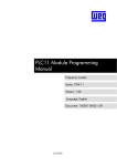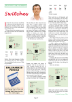
1
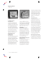
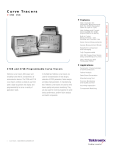
C u r v e Tr a c e r s
370B • 371B
Features & Benefits
High-resolution DC
Parametric Measurements
With the 370B (Resolution
Down to 1 pA or 2 µV)
High Voltage and Current
Sourcing With the 371B
(Up to 3,000 V or 400 A)
Built-in Cursor
Measurements – Dot,
Window and Function Line
Kelvin Sense Measurements
Sweep Measurement Mode
Waveform Comparison
and Averaging
Fully Programmable
1.44 MB Floppy Drive Stores
Setup and Bitmap of Curves
Direct Hardcopy with
Third-party Printer
Applications
370B and 371B Programmable Curve Tracers
Parametric Characterization
of Semiconductors
Failure Analysis
Tektronix curve tracers offer power and
versatility to test the DC characteristics of
semiconductor devices. The 370B and 371B
curve tracers combine a simple-to-use
front panel, digital acquisition and display,
and programmability to serve a variety of
application needs.
1
Curve Tracers • www.tektronix.com/other_tm
In the R&D lab, Tektronix curve tracers
are used for characterization of new
designs, extraction of SPICE parameters,
failure analysis and data sheet generation.
In manufacturing test, Tektronix curve
tracers are used to verify device quality
and process monitoring. They are also
used for incoming inspection to verify
device performance, perform failure
analysis and match components.
Data Sheet Generation
Manufacturing Test
Process Monitoring and
Quality Control
Incoming Inspection
Component Matching
Curve Tracers
370B • 371B
the data, up to 24 characters of text may
be used to label or annotate the curve data.
Operating parameters can be adjusted,
stored and recalled using several storage
methods including the 370B and 371B
system memory, the built-in 1.44 MB
floppy drive, or sent externally via the
GPIB controller.
Automated Cursor
370B.
The World Standard
for High-resolution
Curve Tracers
The 370B, the world standard for highresolution curve tracers, provides up to
20 A/2,000 V sourcing capability combined
with 1 pA and 50 µV measurement resolution. The 370B performs DC parametric
characterization of integrated circuits, transistors, thyristors, diodes, SCRs, MOSFETs,
electro-optic components, solar cells, solidstate relays and other semiconductor
devices. It has push button source and
measurement configuration so it’s easy to
change from one test to the next.
The Industry Leader
in High-power
Curve Tracers
The 371B, the industry leader in high-power
curve tracers, performs DC parametric
characterization on a wide variety of power
semiconductors including thyristors, SCRs,
IGBTs and power MOSFETs. The highvoltage collector mode permits testing the
Off-characteristics of a device up to 3,000
volts. The pulsed high-current collector
mode provides output current pulses
greater than 400 amps peak to test On-
2
Curve Tracers • www.tektronix.com/other_tm
371B.
characteristics and permits high-power
testing up to 3,000 watts. In the sweep
measurement mode, the 371B automatically
constructs a family of curves while stimulating
the device with low-duty-cycle pulses. With
this capability, power curves can be displayed
without excessive heating of the device.
Interactive
Programmable Control
Interactive control of all 370B and 371B
measurements is accomplished from the
full-featured front panel or over the GPIB.
Every operating parameter can be controlled
using the GPIB controller. 370B and 371B
Series LabView drivers are available at the
Tektronix.com web site. These drivers have
many of the building blocks to create a
custom measurement solution.
Store and Recall Setups and
Digitized Curves
Up to 80 digitized characteristic curves can
be stored on a diskette or in internal
non-volatile memory and recalled at the
touch of a button. A live curve can then be
compared with a previously stored curve to
assess temperature drift or other changes
in operating parameters. To help identify
The 370B and 371B provide three cursor
measurement modes. The dot cursor
provides direct screen readout of voltage,
current, gm or DC beta at any point. The
window cursor can be positioned between
two curves to measure small signal beta or
gm and can also be used for visual go/no-go
tests. The function line cursor provides
screen readout of a slope or intercept value.
Sweep Measurement Mode
In the sweep measurement mode, the curve
tracer automatically constructs a family of
curves. The 371B achieves this with low
duty-cycle pulses. With this capability,
power curves can be displayed without
excessive heating of the device.
Direct Hardcopy Printouts
Curve output data can be sent directly from
the 370B and 371B to a Citizen iDP-3240
thermal printer. Printing can continue while
the 370B and 371B perform the next tasks.
Curve Tracers
370B • 371B
Characteristics
370B Curve Tracer Characteristics
Collector Supply
Peak Voltage (Range)
Polarity Modes
Available Current
Peak Current
Peak Current (PULSE mode)
Available Resistance
Minimum Series Resistance
Maximum Series Resistance
Available Peak Power
16, 80 and 400 V Range –
0.08, 0.4, 2, 10, 50, 220 W.
2,000 V Range – 0.08, 0.4, 2, 10, 50 W.
Variable Collector Supply Settings As a %
of Maximum Peak Voltage –
0 to 100% in 0.1% increments.
Looping Compensation (typical) Range –
at least 100 pF.
Step Generator
Accuracy
Incremental – 1.5%.
Absolute –
Less than 1.5% of total output + 3% x STEP
AMPLITUDE setting + 1 mV or 1 nA.
Offset Control Range –
Variable from –10 to +10 times STEP AMPLITUDE.
Resolution – STEP AMPLITUDE setting x 1%.
Current Mode
Amplitude Range –
50 nA to 200 mA in a 1-2-5 sequence
of 21 steps.
Maximum Current –
20x STEP AMPLITUDE setting, 10x STEP
AMPLITUDE setting when control is set
to 200 mA.
Maximum Voltage – At least 10 V.
Maximum Opposing Offset Current –
10x STEP AMPLITUDE.
Maximum Opposing Volts – Less than 15 V.
Ripple Plus Noise –
Less than 0.5% x STEP AMPLITUDE + 10 nA.
16 V
80 V
400 V
AC, ± DC, ± Leakage, ± Rectified Sine
2,000 V
10 A
20 A
2A
4A
0.4 A
0.8 A
0.05 A
0.1 A
0.26 Ω
800 Ω
6.4 Ω
20 kΩ
160 Ω
500 kΩ
20 kΩ
12.5 MΩ
Voltage Mode
Amplitude Switch Range –
50 mV to 2 V, in a 1-2-5 sequence of six steps.
Maximum Voltage – 20x STEP AMPLITUDE.
Maximum Current –
At least 500 mA at 10 V or less, at least
200 mA at 15 V, at least 10 mA at 40 V.
Short Circuit Current Limiting –
500 mA, +50%, –20%.
Maximum Opposing Offset Current –
10x STEP AMPLITUDE.
Maximum Opposing Current –
Less than 20 mA.
Ripple Plus Noise –
Less than 0.5% x STEP AMPLITUDE + 10 mV.
Step Rates –
2x line frequency (1x line frequency in AC
collector supply mode). Steps occur at
0 collector voltage.
Pulsed Steps – 80 µs or 300 µs wide, ±10%.
Steps and Offset Polarity –
Corresponds to Collector Supply Polarity when
STEP GENERATOR POLARITY INVERT is
disabled. Opposite to Collector Supply Polarity
when STEP GENERATOR POLARITY INVERT is
selected or CONFIGURATION switch is set to
BASE COMMON. BASE COMMON configuration
disables STEP GENERATOR POLARITY INVERT.
Number of Steps – Ranges from 0 to 10.
AUX Supply
Range – From –40 to +40 volts, with 20 mV step
resolution.
Accuracy (typical) –
Within 50 mV + 1.5% of total output.
Output Current –
At least 100 nA at ±20 V.
At least 10 mA at ±40 V.
Ripple Plus Noise – Less than 50 mVp-p.
Curve Tracers • www.tektronix.com/other_tm
3
Curve Tracers
370B • 371B
Max. Volts Range
16 V
80 V
400 V
2000 V
Noise or Ripple
1 nAp-p
1 nAp-p
2 nAp-p
5 nAp-p
Non-store
Vertical Deflection System
Collector/Base Current
Range –
1 µA/div to 2 A/div in a 1-2-5 sequence.
X10 MAG extends maximum sensitivity to
100 nA/div (1 nA resolution).
Accuracy (typical) –
Within 2% of WINDOW cursor readout
+ 0.1 x VERT/DIV setting.
Emitter Current
Range –
1 nA/div to 2 mA/div in a 1-2-5 sequence
X10 MAG extends maximum sensitivity to
100 pA/div.
Accuracy (typical) –
Within 2% of WINDOW cursor readout
+ 0.1 x VERT/DIV settings + 1 nA.
Maximum Displayed Noise or Ripple –
Depending on setting of MAX PEAK VOLTS.
Step Generator Display
Range –
1 step/division.
1 step/10 divisions with X10 MAG.
10 steps/division with STEP MULTI .1x.
Accuracy – Within 0.3 division.
4
Curve Tracers • www.tektronix.com/other_tm
Display Offset (typical)
Range – ±10 divisions with 0.1 div resolution.
Accuracy –
Within 1.5% of offset + 0.1 x VERT/DIV setting.
Display X10 MAG (typical)
Accuracy –
Within 1.5% of window cursor readout
+ 0.3 x VERT/DIV setting.
Display Invert (typical)
Accuracy – Within 0.1 x VERT/DIV setting.
Digital Storage
Vertical Acquisition
A/D Converter
Resolution –
10-Bits for 10.24 divisions, 100 counts
per division.
Max. Data Points – 1024.
Max. Sampling Rate – Line frequency x 1024.
Min. Sampling Rate – Line frequency x 2.
Collector/Base Current
Range –
1 µA/div to 2 A/div in a 1-2-5 sequence.
X10 MAG extends maximum sensitivity to
100 nA/div (1 nA resolution).
Accuracy –
Within 1.5% of DOT cursor readout
+0.05 x VERT/DIV setting.
Emitter Current
Range –
1 nA/div to 2 mA/div in a 1-2-5 sequence.
X10 MAG extends max sensitivity to 100 pA/div
(1 pA resolution).
Accuracy –
Within 1.5% of DOT cursor readout +0.05 x
VERT/DIV setting + 1 nA.
Step Generator Display
Range –
1 step/division, 1 step/10 divisions with
X10 MAG, 10 steps/division with
STEP MULTI .1x.
Accuracy – Within 0.3 division.
Display Offset (typical)
Range – ±10 divisions with 0.1 div resolution.
Accuracy –
Within 1.5% of offset + 0.06
x VERT/DIV setting.
Display X10 MAG (typical)
Accuracy –
Within 1.5% of window cursor readout + 0.3 x
VERT/DIV setting.
Display Invert (typical)
Accuracy – Within 0.04 x VERT/DIV setting.
Curve Tracers
370B • 371B
Non-store Horizontal
Deflection System
Collector Volts
Range –
50 nV/div to 500 V/div in a 1-2-5 sequence.
X10 MAG extends maximum sensitivity to
5 mV/div (50 µV resolution).
Accuracy (typical) –
Within 2% of WINDOW cursor readout
+ 0.1 x HORIZ/DIV setting.
Base/Emitter Volts
Range –
50 mV to 5 V/div in a 1-2-5 sequence.
X10 MAG extends maximum sensitivity to
5 mV/div (50 µV resolution).
Accuracy (typical) –
Within 2% of WINDOW cursor readout
+ 0.1 x HORIZ/DIV setting.
Step Generator Display
Range –
1 step/division, 1 step/division with X10 MAG,
10 steps/division with STEP MULTI .1x.
Accuracy – Within 0.3 division.
Display X10 MAG
Accuracy –
Within 1.5% of window cursor readout + 0.3 x
HORIZ/DIV setting.
Display Invert
Accuracy – Within 0.1 x HORIZ/DIV setting.
Digital Storage Horizontal
Acquisition
A/D Converter
Resolution –
10 bits for 10.24 divisions, 100 counts
per division.
Max. Data Points – 1024.
Max. Sampling Rate – Line frequency x 1024..
Min. Sampling Rate – Line frequency x 2.
Collector Volts
Acquisition Modes
Normal, Envelope, and Average.
Envelope is Vertical or Horizontal.
Average is moving average with weight of 1/16.
Safety
Standards Met –
UL3111-1, CAN/CSA C22.2 NO. 1010.1,
EN 61010-1 with second amendment.
Collector Supply
Modes (positive and negative polarities
for both modes) –
High current: 250 µs pulses with maximum peak
of 30 V.
High voltage: Full rectified sine wave with maximum
peak of 3,000 V.
Polarity Modes –
NPN +.
PNP –.
Range –
50 mV/div to 500 V/div in a 1-2-5 sequence.
X10 MAG extends maximum sensitivity to
5 mV/div (50 µV resolution).
Accuracy –
Within 1.5% of DOT cursor readout
+ 0.05 x HORZ/DIV setting.
Display Offset
Range –
±10 divisions in 0.1 division steps.
Accuracy –
Within 1.5% of offset + 0.1 x HORIZ/DIV setting.
Curve Tracers • www.tektronix.com/other_tm
5
Curve Tracers
370B • 371B
3 7 1 B C u r v e Tr a c e r C h a r a c t e r i s t i c s
High Voltage
Mode
Peak Power Watts
(range)
High Current
(pulsed) Mode
High Current
(pulsed) Mode
30 mW
300 mW
3W
30 W
300 W
3 kW
Collector
Peak Current
0.4 mA ±20%
4 mA ±20%
4 mA ±20%
40 mA ±20%
40 A
400 A
Maximum
Peak Voltage
300 V + 15% – 0%
300 V + 15% – 0%
3 kV + 10% – 0%
3 kV + 10% – 0%
30 V + 10% – 5%
30 V + 10% – 5%
Variable Collector Supply Range –
Continuously variable from 0% to 100%
in 0.1% increments.
Looping Compensation (high voltage mode) –
Stray capacitance between collector terminal
and ground is compensated for up to a
maximum of 100 pF.
Pulsed Collector Supply Repetition Rate –
3 kW: 1/4 (0.25 x) line frequency.
300 W: 1/2 (0.5 x) line frequency.
Pulse Width (half amplitude) –
250 µs ±10% (more than 30% of collector supply).
Circuit Breakers –
Both the high-voltage and the high-current supplies
have breakers which operate independently. The
high-current output breaker opens automatically in
an over-current condition. Both breakers can be
operated manually.
Current Mode
Amplitude Range
Normal Step –
1 µA to 2 mA in 1-2-5 sequence. COLLECTOR
SUPPLY HIGH VOLTAGE MODE (30 W/3 W and
300 mW/30 mW).
Pulsed Step –
1 mA to 2 A in 1-2-5 sequence. COLLECTOR
SUPPLY HIGH CURRENT MODE (3 kW/300 W).
Maximum Current –
20 x step amplitude, except 10 times
STEP/OFFSET AMPLITUDE when control is
set to 2 A per step.
Maximum Voltage –
12 V ±30%.
Accuracy: At least 5 V.
Ripple Plus Noise –
Within 1% of STEP AMPLITUDE + 10 nA.
Step Generator
Offset Control Range –
Variable 0 to 10 times STEP/OFFSET AMPLITUDE
setting. However, 0 to 5 times when STEP/OFFSET
AMPLITUDE is 5 V or 2 A.
Number of Steps –
0 to 10. However, 0 to 5 when STEP/OFFSET.
Step Polarity – Positive, Negative.
Step Rate –
Pulse:
3 kW: 1/4 (0.25x) the line frequency,
300 W: 1/2 (.5X) the line frequency.
Stairstep:
300 W, 3 W, 300 mW, 30 mW: 2x the
line frequency.
6
Curve Tracers • www.tektronix.com/other_tm
Voltage Mode
Step Amplitude Range –
200 mV to 5 V in 1-2-5 sequence.
Short Circuit Current Limiting –
100 mA +50%, –20%.
Maximum Voltage –
10 x STEP AMPLITUDE, with 5 V setting.
20 x STEP AMPLITUDE, except 5 V setting.
Ripple Plus Noise –
Within 1% of STEP AMPLITUDE + 10 mV.
Vertical Deflection System
Collector Current (lc) Range
3 kW Peak Power – 1 A/DIV to 50 A/DIV.
300 W Peak Power – 500 mA/DIV to 5 A/DIV.
30 W Peak Power – 100 µA/DIV to 5 mA/DIV.
3 W Peak Power – 10 µA/DIV to 500 µA/DIV.
0.3 W Peak Power – 10 µA/DIV to 500 µA/DIV.
0.03 W Peak Power – 1 µA/DIV to 50 µA/DIV.
Collector Current (lc) Accuracy –
Within 0.1 DIV to the Vertical graticule lines.
Collector Current (lc) Cursor Accuracy –
Within 1.5% of readout +0.1 DIV of the
CURRENT/DIV setting.
Horizontal Deflection System
Collector Supply Volts (Vce) Range
3 kW, 300 W Peak Power –
100 mV/DIV to 5 V/DIV in a 1-2-5 sequence.
30 W, 3 W Peak Power –
50 V/DIV to 500 V/DIV in a 1-2-5 sequence.
300 mW, 30 mW Peak Power –
5 V/DIV to 50 V/DIV in a 1-2-5 sequence.
Step Generator Volts (Vbe) Range –
100 mV/DIV to 5 V/DIV in a 1-2-5 sequence.
Step Generator Volts (Vbe) Accuracy –
Within 0.1 DIV of Horizontal graticules.
Digital Storage Acquisition
A/D Converter
Resolution –
10 bits for 1024 division, 100 points
per one division.
Tolerance – Within ±2 counts.
Max. Data Point – 1024.
Max. Sample Rate – 1024 x line frequency.
Min. Sample Rate – 1/8 x line frequency.
Safety
Standards Met –
UL3111-1, CAN/CSA C22.2 NO. 1010.1,
EN 61010-1 with second amendment.
Curve Tracers
370B • 371B
Ordering Information
370B
371B
Power Plug Options
High-Resolution Programmable Curve Tracer.
High-Power Programmable Curve Tracer.
370B Standard Accessories
371B Standard Accessories
A1001– Blank adapter for mounting custom
sockets.
A1002– In-line transistor adapter.
A1005– Axial diode lead adapter.
User Manual– Order 070-A838-00 (English).
Protective Cover– Order 337-3344-02.
Power Cord– Order 161-0066-00.
Fuses–
Order 159-0260-00 (125 V, 4 A).
Order 159-0259-00 ( 250 V, 2 A).
Utility Software– Order 063-3341-02.
A1002– In-line transistor adapter.
User Manual– Order 070-A840-00 (English).
Power Cord– Order 161-0066-00.
Wire Set– Order 012-1371-00.
Fuses–
Order 159-0291-00 (250 V, 1 A).
Order 159-0238-00 (250 V, 4 A).
Utility Software– Order 063-3341-02.
Opt. A1– Euro Plug, 220V, 50 Hz.
Opt. A2– UK Plug, 240V, 50 Hz.
Opt. A3– Australian Plug, 240V, 50 Hz.
Opt. A5– Swiss Plug, 220V, 50 Hz.
Opt. AC– China Plug, 50 Hz.
Opt. A9– No power cord, set to 220/240 V.
370B Recommended
Accessories
Service Manual– Order 071-A842-00.
K4000– Instrument cart.
Rackmount kit– Order 016-0930-00 (Opt. 1R).
371B Recommended
Accessories
A1001– Blank adapter for mounting custom
sockets.
A1005– Axial lead adapter.
Service Manual– Order 070-A843-00.
K4000– Instrument cart.
Rackmount Kit– Order 016-0930-00 (Opt. 1R).
Service
Opt. C3– Calibration Service 3 Years.
Opt. C5– Calibration Service 5 Years.
Opt. D1– Calibration Data Report.
Opt. D3– Calibration Data Report 3 Years (with
Option C3).
Opt. D5– Calibration Data Report 5 Years (with
Option C5).
Opt. R3– Repair Service 3 Years.
Opt. R5– Repair Service 5 Years.
Curve Tracers • www.tektronix.com/other_tm
7
Curve Tracers
Contact Tektronix:
ASEAN / Australasia (65) 6356 3900
370B • 371B
Austria +41 52 675 3777
Balkan, Israel, South Africa and other ISE Countries +41 52 675 3777
Belgium 07 81 60166
Brazil & South America 55 (11) 3741-8360
Canada 1 (800) 661-5625
Central East Europe, Ukraine and the Baltics +41 52 675 3777
Central Europe & Greece +41 52 675 3777
Denmark +45 80 88 1401
Finland +41 52 675 3777
France +33 (0) 1 69 86 81 81
Germany +49 (221) 94 77 400
Hong Kong (852) 2585-6688
India (91) 80-22275577
Italy +39 (02) 25086 1
Japan 81 (3) 6714-3010
Luxembourg +44 (0) 1344 392400
Mexico, Central America & Caribbean 52 (55) 5424700
Middle East, Asia and North Africa +41 52 675 3777
The Netherlands 090 02 021797
Norway 800 16098
People’s Republic of China 86 (10) 6235 1230
Poland +41 52 675 3777
Portugal 80 08 12370
Republic of Korea 82 (2) 528-5299
Russia & CIS +7 (495) 7484900
South Africa +27 11 254 8360
Spain (+34) 901 988 054
Sweden 020 08 80371
Switzerland +41 52 675 3777
Taiwan 886 (2) 2722-9622
United Kingdom & Eire +44 (0) 1344 392400
USA 1 (800) 426-2200
For other areas contact Tektronix, Inc. at: 1 (503) 627-7111
Updated 12 May 2006
Our most up-to-date product information is available at:
www.tektronix.com
Copyright © 2006, Tektronix. All rights reserved. Tektronix products are covered by
U.S. and foreign patents, issued and pending. Information in this publication supersedes that in all previously published material. Specification and price change privileges reserved. TEKTRONIX and TEK are registered trademarks of Tektronix, Inc.
All other trade names referenced are the service marks, trademarks or registered
trademarks of their respective companies.
05/06
8
Curve Tracers • www.tektronix.com/other_tm
DV/WOW
76W-10757-3