1
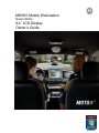
MW810 Mobile Workstation
Model F5208A
8.4” LCD Display
Owner’s Guide
6802982C85-C
2
6802982C85-C
3
MW810 8.4” Display Owner’s Manual C
COMPUTER SOFTWARE COPYRIGHTS
The Motorola products described in this instruction manual may include copyrighted Motorola
computer programs stored in semiconductor memories or other media. Laws in the United States
and other countries preserve for Motorola certain exclusive rights for copyrighted computer
programs, including the exclusive right to copy or reproduce in any form the copyrighted
computer program. Accordingly, any copyrighted Motorola computer programs contained in the
Motorola products described in this instruction manual may not be copied or reproduced in any
manner without the express written permission of Motorola. Furthermore, the purchase of
Motorola products shall not be deemed to grant either directly or by implication, estoppel or
otherwise, any license under the copyrights, patents or patent applications of Motorola, except for
the normal non-exclusive, royalty free license to use that arises by operation of law in the sale of
a product.
COPYRIGHT
Copyright © 2010 Motorola Inc. All rights reserved. No part of this manual may be transmitted,
stored in a retrieval system, or translated into any language or computer language, in any form or
by any means, without the prior written permission of Motorola Inc.
TRADEMARKS
•
•
•
•
MOTOROLA and the Stylized M Logo are registered in the U.S. Patent and Trademark
Office.
Microsoft, Windows and the Windows logo are registered trademarks of Microsoft
Corporation.
Broadcom is a registered trademark of Broadcom Incorporated.
VESA is a registered trademark of the Video Electronics Standard Association.
All other trademarks, registered trademarks, product or service names are the property of their
respective owners.
WARRANTY DISCLAIMER
Motorola may add, delete, change, or withdraw, in whole or in part, this document or software
described in this document at any time and without notice. Such document modifications will be
incorporated in new releases of this document on an intermittent basis. Motorola disclaims any
responsibility for labor or material cost involved by persons outside the company as a result of
using this document.
6802982C85-C
4
COMPLIANCE INFORMATION
Compliance Notice for US
The FCC requires that manuals pertaining to Class A and Class B computing devices must
contain warnings about possible interference with local residential radio and TV reception.
This equipment has been tested and found to comply with limits for a Class B digital device,
pursuant to Part 90 of the FCC Rules. These limits are designed to provide reasonable protection
against harmful interference when the equipment is operated in a commercial or residential
environment. This equipment generates, uses, and can radiate radio frequency energy and, if not
installed and used in accordance with the instruction manual, may cause harmful interference to
radio communications.
This device complies with Part 90 of the FCC Rules. Operation is subject to the following two
conditions:
(1) This device may not cause harmful interference.
(2) This device must accept any interference received, including interference that may cause
undesired operation.
For detailed product safety and RF exposure for mobile workstations, with two-way radios,
installed in vehicles, refer to Electromagnetic Emission (EME) safety leaflet, Motorola publication
number 68P02967C16.
Compliance Notice for Canada
The class B digital device complies with Canada ICES – 003.
Compliance Notice for European Union Countries
The device complies with the requirements of the EEC directive 89/336/EEC as amended by
92/31/EEC and 93/68/EEC art.5 with regard to 'Electromagnetic compatibility' and 73/23/EEC as
amended by 93/68/EEC art.13 with regard to 'Safety'.
FCC Warning
To assure continued FCC compliance, the user must use grounded power supply cord and
cables which are included with the equipment or specified. Unauthorized changes or
modifications made in the CPU or Display, not expressly approved by Motorola, will void the
user's authority to operate the equipment.
6802982C85-C
5
MW810 8.4” Display Owner’s Manual C
Contents
Using This Manual ................................................................................................................................................................. 7
Who Should Use this Manual ........................................................................................................................................... 7
Introduction to Manual ...................................................................................................................................................... 7
Related Manuals............................................................................................................................................................... 7
Conventions Used in This Manual.................................................................................................................................... 8
Getting Started....................................................................................................................................................................... 9
What is the Display?......................................................................................................................................................... 9
Getting the Display Running........................................................................................................................................... 10
Unpacking ................................................................................................................................................................. 10
Installation and Connecting to Car Battery ............................................................................................................... 10
Turning On the Display for the First Time ................................................................................................................. 10
Taking a Look at the Display ............................................................................................................................................... 11
8.4" Display Front View............................................................................................................................................. 11
Display Indicators...................................................................................................................................................... 12
Connections ......................................................................................................................................................................... 13
USB Device .................................................................................................................................................................... 13
Connecting the laptop .................................................................................................................................................... 13
Display Configuration........................................................................................................................................................... 14
Display Configuration Parameters.................................................................................................................................. 14
Display Configuration Change........................................................................................................................................ 15
Maintenance Programming Software........................................................................................................................ 15
How to Modify Configuration Parameters ................................................................................................................. 15
Basic Operations.................................................................................................................................................................. 18
Power On........................................................................................................................................................................ 18
Power Off........................................................................................................................................................................ 19
Standby .......................................................................................................................................................................... 20
Wake Up......................................................................................................................................................................... 20
OSD Button .................................................................................................................................................................... 21
Emergency key............................................................................................................................................................... 21
Function keys ................................................................................................................................................................. 21
Illumination Control......................................................................................................................................................... 23
Brightness Control .......................................................................................................................................................... 23
Touch Screen Calibration ............................................................................................................................................... 23
Backward Compatibility .................................................................................................................................................. 23
Display Software .................................................................................................................................................................. 24
Video Controller.............................................................................................................................................................. 24
Embedded Controller...................................................................................................................................................... 24
Display Software............................................................................................................................................................. 24
Display Control ............................................................................................................................................................... 25
Display DLL .................................................................................................................................................................... 25
Extrakey.......................................................................................................................................................................... 25
MW Manager .................................................................................................................................................................. 25
Display Adjustment .............................................................................................................................................................. 27
Setting the Timing Mode................................................................................................................................................. 27
Embedded On-Screen Display Control .......................................................................................................................... 27
Main Menu ................................................................................................................................................................ 28
Volume Control ......................................................................................................................................................... 28
Video Control (Main Menu) ....................................................................................................................................... 28
Color Control ............................................................................................................................................................. 29
Display Adjust ........................................................................................................................................................... 30
Tools ......................................................................................................................................................................... 31
Mobile and Office Configurations......................................................................................................................................... 33
Display Configuration Tips.............................................................................................................................................. 33
Office Mode............................................................................................................................................................... 33
Mobile Mode.............................................................................................................................................................. 33
Disable Power Button ............................................................................................................................................... 33
Configuration for ML910 Laptop ..................................................................................................................................... 34
Display Upgrade .................................................................................................................................................................. 35
Description/Tutorial......................................................................................................................................................... 35
Display Firmware............................................................................................................................................................ 35
Display Drivers ............................................................................................................................................................... 35
Display Service............................................................................................................................................................... 36
Getting Assistance ............................................................................................................................................................... 37
Appendix A:
Safety Instructions.............................................................................................................................. 38
Appendix B:
Warranty Information .......................................................................................................................... 39
Appendix C:
Display Specifications......................................................................................................................... 42
6802982C85-C
6
Appendix D:
Appendix E:
Troubleshooting Information............................................................................................................... 45
Acronyms and Abbreviations .............................................................................................................. 46
6802982C85-C
7
MW810 8.4” Display Owner’s Manual C
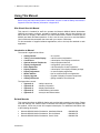
Using This Manual
Before using this manual and products it describes, be sure to read the Safety instructions in
Appendix A and the Warranty information in Appendix B.
Who Should Use this Manual
This manual is intended for staff who operate the Motorola MW810 Mobile Workstation
(MW810) and need to configure, upgrade or maintain its display, which is also referred to as
either device or Display in this manual. This manual assumes the reader is familiar with the
MW810 and basic Windows operations. If this is not the case, be sure to read the MW810
User’s Guide and documentation that came with your version of Windows.
For documentation of supplied software applications, refer to the help file attached to each
application.
Introduction to Manual
The manual is organized as follows:
•
•
•
•
•
•
•
•
•
•
•
Getting Started
Taking a Look at the Display
Connections
Optional Internal Peripherals
Display Configuration
Basic Operations
Display Software
Display Adjustment
Mobile & Office
Display Upgrade
Getting Assistance
- an overview
- a brief functional explanation
- a description of the display connections
- internal peripheral devices
- configuration upon turning on
- a brief description of basic operations
- a description of the display software package
- on-screen-display adjustment
- tips for mobile and office configurations
- upgrade of display's firmware components
- getting assistance from Motorola
The Appendices contain:
•
•
•
•
•
Appendix A
Appendix B
Appendix C
Appendix D
Appendix E
- safety instructions
- warranty information
- display specifications
- troubleshooting information
- acronyms and abbreviations
Related Manuals
This manual describes the MW810 display and provides basic operating instructions. Please
note that although this manual refers to hardware and software components supplied with
this product, it does not provide full component description. For additional information refer
to the following documents:
•
•
•
Motorola MW810 Mobile Workstation, Installation Manual
Motorola MW810 Mobile Workstation, Service Manual
Motorola MW810 Mobile Workstation, User’s Guide
6802982C85-C
- 6802982C80
- 6802982C70
- 6802981C80
8
•
•
Motorola MW810 Mobile Workstation, CPU Owner’s Guide
- 6802982C81 (MW810
R1.1) or 6802987C40 (MW810 R1.2)
Motorola MW810 Mobile Workstation, Software Development Kit - 6802983C00
For documentation of software applications supplied with this product, refer to the help file
attached to each application. This manual is designed to supplement the on-line help or online context-sensitive help installed with every software component. Please review this
information to ensure proper use of the product.
If you need to change the configuration of your device, refer to
•
Motorola MW810 Mobile Workstation,
Maintenance Programming Software, User’s Manual
- 6802982C95
Also, if you need to install Windows operating system software supporting the display's
functionality, refer to
•
Motorola MW810 Mobile Workstation,
Field Support Kit, User’s Manual
- 6802982C90
For additional information visit the MW810 home page http://www.motorola.com.
Conventions Used in This Manual
Throughout this publication, you will notice the use of danger and caution marks. These
notations are used to emphasize that safety hazards exist, and care must be taken. Do not
proceed beyond a DANGER or CAUTION until the indicated conditions are fully understood
and met.
The following conventions are used throughout this manual:
Italics
Used for emphasis and for new terms.
CAPITAL LETTERS
Used to designate configuration parameters and options.
Bold
Used to indicate keyboard keys or application buttons.
Program Æ Motorola Æ MW810 CPU
Used to designate the location and name of a menu function. For
example, Program Æ Motorola Æ MW810 CPU Æ CPU Manager
launch CPU Manager program.
Æ CPU Manager
NOTE:
Indicates an operational procedure, practice, or condition to which
you should pay special attention.
CAUTION:
Alerts you of conditions, which can result in loss or corruption of data,
or damage to device.
DANGER:
Indicates a potentially hazardous situation, which, if not avoided, may
result in injury. It may also be used to alert against unsafe practices
and property-damage-only accident hazards.
6802982C85-C
9
MW810 8.4” Display Owner’s Manual C
Getting Started
The Motorola MW810 Mobile Workstation (MW810) is a high-performance computing
platform, optimized to deliver seamless mobility at highway speeds. Motorola’s three-piece
design allows flexible installation options, including choice and location of CPU configuration,
display, and backlit keyboards.
•
Ruggedness
Operates with confidence in mobile environments and under stressful conditions.
•
Fixed-Mount System for Vehicles
Provides mobile connectivity and computing power for vehicle users. Internal GPS
module options work with your applications to provide accurate vehicle location so
you can manage your fleet and deploy resources more effectively.
•
Versatile Three-Piece Design
Allows for flexibility and ease of installation in space-limited vehicles. Individual
components can be purchased separately.
•
High Performance Display
Transmissive, high contrast backlit displays offer outstanding performance even in
the most difficult lighting conditions. Display design enables shortcuts to the most
important user functions.
•
Optimized for Wireless.
Expanded wireless networking capabilities, including new internal cellular modem
options, for better access to information.
The Motorola MW810 offers a range of integrated radios and GPS options so the vehicle
user can stay connected via one or more wireless networks. Optional expansion boards
provide a wide range of I/O ports to support external radios, dual displays, and peripheral
devices.
What is the Display?
The MW 810 offers the rugged display:
•
8.4” SVGA high brightness display
TFT-technology display with 800 NIT (800 Cd/m2) LCD backlighting.
All displays offer features as follows:
•
The screen made of tempered glass which is covered by a protective film to prevent the
glass from shattering in the event of breakage
•
A touch screen that can be activated with either a gloved finger or a stylus pen
•
Sealing against moisture
•
2 USB 2.0 ports for connectivity with external USB devices
•
Support analog RGB and digital DVI video inputs
•
On-chip OSD for high-quality programmable menus
•
Compatible with VESA resolution standards
•
VESA display data channel (DDC) compatible
6802982C85-C
10
Getting the Display Running
This section guides you through procedures to get the Display ready for operation.
Unpacking
Unpack your shipment and check the contents to ensure that you have received all the
specified items.
If your display is shipped as stand-alone device, after unpacking the shipping carton, the
following items should be found:
•
•
•
•
Display box
Power cable
CPU-to-Display cable
Field support CD with this Owner’s Guide
If your display is part of the MW810 Mobile Workstation, refer to the Motorola MW810 Mobile
Workstation User’s Guide for a list of shipped items.
The MW810 Field Support Kit CD-ROM is included in the delivery scope. You will find further
information on the system, drivers, utilities, updates, manuals on this CD.
Inspect all the items. If any item is missing or damaged, notify your Motorola Customer
Service representative immediately.
NOTE: Save the packing carton and anti-static plastic bag for storage and shipping. Both the
shipping carton and the anti-static bags protect the display components from physical and
electrostatic damage.
Installation and Connecting to Car Battery
Please, refer to the Motorola MW810 Mobile Workstation Installation Manual and strictly
follow the installation procedure. Be aware that your device can be damaged if improperly
installed.
Turning On the Display for the First Time
When the installation is completed, perform the following procedures to turn on the display.
•
•
Press the power button
Wait until Windows operating system starts
Read in the Display Configuration chapter about a variety of parameters that define
functionality of the display when you turn it on. Modify configuration parameters if required.
6802982C85-C
11
MW810 8.4” Display Owner’s Manual C
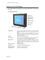
Taking a Look at the Display
This chapter identifies the components of the display and provides a brief functional
description.
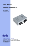
8.4" Display Front View
POWER BUTTON
Turns the display power ON and OFF. This button functions
identically as the Power Button on the front panel of the CPU
box.
NOTE: If the display is used with the MW810 CPU, the main
power switch on the rear CPU panel must be switched on before
using the Power Button.
SPEAKER
Used for audio and alert signaling.
FUNCTION KEYS
6 function buttons to facilitate specific operations. The function of
each button is set via a pre-installed software application
EMERGENCY KEY
Use this button to signal an emergency event to software
emergency application, installed in the workstation. The
Emergency button becomes functional as soon as the operating
system is running.
BACKLIGHT CONTROL
Backlight on/off button.
OSD BUTTON
On-Screen-Display for display controls.
BRIGHTNESS CONTROL
Bightness up- and down buttons.
VOLUME CONTROL
Volume up- and down buttons.
6802982C85-C
12
Display Indicators
The display has two LED indicators that are located at the front panel (Display Mode and
Display Temperature) and Emergency LED at the top.
These LED's alongside with display illumination provide the following indication about
operational conditions.
STATE
DISPLAY
TEMP
EMERG
KEY
BACK
ILLUM
BACKL
CTRL
MODE LED
LED
LED
Power off
OFF
OFF
OFF
OFF
OFF
OFF
Video on (normal operational mode)
Green
OFF
ON
ON
ON
ON
Video on (low temperature, heater
on)
Green
Red
ON
ON
ON
ON
Video on (high temperature)
Green
Red
ON
ON
ON
ON
Video off
Yellow (50%
ON
ON
ON
OFF
ON
ON
ON
ON
ON (50%
OFF
OFF
OFF
LIGHT
intensity)
No video cable*
Yellow (50%
intensity)
System standby mode
Yellow (50%
OFF
intensity)
intensity)
Backlight off
Green
ON
OFF
ON
OFF
Low car battery voltage
Yellow
ON
ON
ON
ON
NOTE: When there is no video cable connected to the display, No Cable message will pop
up on the screen for 3 seconds and then disappear.
6802982C85-C
13
MW810 8.4” Display Owner’s Manual C
Connections
The display has three USB 2.0 ports for connection an external USB device and a connector
for attaching the cable from the MW810 CPU or another laptop or desktop.
CAUTION: Do not connect or disconnect any external device during the BIOS boot process
or when the CPU is in power-saving mode.
USB Device
USB devices are hot-pluggable. This means you can connect and disconnect devices while
your operating system is running. Using USB 2.0 ports you can connect external low, high,
and full-speed USB clients. Display USB 2.0 ports support transfer rates up 480 MB/s.
To connect a USB device, simply plug the device cable to one of the USB ports. The devices
you connect to the USB ports usually require installing a driver, as the required software is
already included in the operating system. However, if the USB device requires its own
software, please install it from the data carrier provided with the device.
CAUTION: do not use right- and left-side USB ports for permanent connections. Always
disconnect USB accessories from these ports when driving.
CAUTION: a device connected to the USB port should not consume more than 0.5A.
Otherwise, the system will not operate properly.
Connecting the laptop
Follow instructions below when you need to connect the display to a laptop:
•
Switch off the laptop and the display
•
Connect the data cable to the laptop’s monitor connection
•
First switch on the display and then the laptop
Use Motorola original integrated molded cables for connection to the MW810 or 3rd-party
CPU's. For details see MW810 Installation Manual.
6802982C85-C
14
Display Configuration
The device has codeplug - a protected memory area to store the configuration parameters
accessed when you turn on the display. That binary-format data contains basic information
about display capabilities including general settings, power-up, power-off modes, etc.
This section describes various configuration parameters that can be selected and modified if
required.
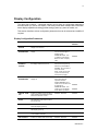
Display Configuration Parameters
PARAMETER
DESCRIPTION
AVAILABLE OPTIONS
FACTORY
SETTING
POWER
SOURCE
Specifies a kind of car battery the
display is connected to.
9V or 12/24V
12/24V
POWER UP
PREFERENCES
Selects desired source to turn on the
display.
USB 5V PRESENCE Turn on the front edge of
USB 5V signal.
ENABLE
POWER BUTTON - Turn
on pressing of the Power
Button on CPU or Display
units.
DISPLAY
POWER UP
OPTIONS
Provides several options to power on
the display while the CPU is off.
TURN ON - Power on and
wait for the CPU power up
without any time limitation.
ENABLE
TURN ON
IGNORE - Do not power on
if the CPU is Off.
WAIT - Power on and wait
up to 10 seconds for any
CPU power up trigger.
POWER DOWN
PREFERENCES
Selects desired method to turn the
display off.
CPU REQUEST – Turn off
when CPU power-off
request is received.
USB 5V ABSENCE -Turn
off as soon as the CPU unit
is powered off.
ENABLE
ENABLE
POWER BUTTON - Turn
off as soon as the display
Power Button is pressed.
ENABLE
CRITICAL TURN
OFF
Enables or disables turning the device
off by pressing and holding the power
button for 6 seconds or more.
ENABLE / DISABLE
ENABLE
POWER OFF
EVENT
Enables or disables sending Power
Off notification to the CPU in order to
turn the CPU off.
ENABLE / DISABLE
ENABLE
BLUETOOTH
Specifies the state of the Bluetooth
radio after display power up.
ON / OFF
ON
SPEAKER
Specifies a state of internal speaker
after display power up.
UNMUTE / MUTE
UNMUTE
1W SUPPORT
Specifies whether the display support
1-wire interface with CPU.
ENABLE / DISABLE
DISABLE
OSD CONTROL
Enables or disables OSD functionality.
ENABLE / DISABLE
ENABLE
6802982C85-C
15
MW810 8.4” Display Owner’s Manual C
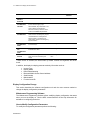
PARAMETER
DESCRIPTION
AVAILABLE OPTIONS
FACTORY
SETTING
OSD BUTTON
DEFAULT
FUNCTION
Defines the OSD button function.
DISABLE / FULL / SIMPLE
*
FULL
KEY
ILLUMINATION
CONTROL
Enable or disable illumination of
function and emergency keys.
ENABLE / DISABLE
ENABLE
TYPE OF
ILLUMINATION
Auto means illumination level of
labels, function and emergency keys is
correlated with the LCD brightness.
AUTO / MANUAL
AUTO
When disabled, keys illumination is off;
when enabled, keys illumination
behaves according to selection of the
TYPE of ILLUMINATION parameter.
Manual means a constant level of
LED's, labels, function and emergency
keys illumination.
FUNCTION KEY
ILLUMINATION
LEVEL
Defines a constant level of illumination
for function keys.
Control range from 0 to 31
15
NOTIFICATION
LED
ILLUMINATION
LEVEL
Defines a constant level of illumination
for Notification LED's.
Control range from 0 to 31
5
BRIGHTNESS
Defines relative brightness level,
which cannot be exceeded by this
display.
Control range from 50 to
100%
100%
FACTOR
* When
levels.
SIMPLE
is selected, the OSD button by default controls the brightness and audio
In addition, the display's codeplug presents read-only information such as:
•
•
•
•
•
•
•
Inverter Type
Display Model
Date of Manufacturing
Bluetooth Media Access Control address
Serial Number
Main board ID
Function board ID
Display Configuration Change
This section describes the software configuration tool and the most common method to
change the display configuration parameters.
Maintenance Programming Software
The Maintenance Programming Software allows modifying display configuration that starts
when you turn the display on. Use the MPS context-sensitive on-line help information for
assistance in configuring the device.
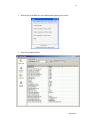
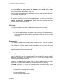
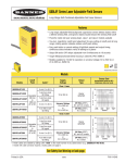
How to Modify Configuration Parameters
To modify the configuration parameters perform the following:
6802982C85-C
16
•
Double-click on the MPS icon; main MPS window appears on the screen.
•
Click on the Codeplug Editor
6802982C85-C
17
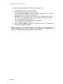
MW810 8.4” Display Owner’s Manual C
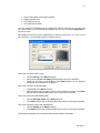
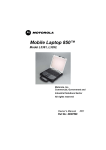
To modify configuration parameters use the MPS tool as shown next:
•
Select Display as a device to be programmed.
•
Select a type of the display (Primary or Secondary).
•
Click on Read from Display to read the codeplug parameters. If your device is
successfully read, you will see a list of parameters.
CAUTION: Incorrect configuration can make the device unworkable. Please, make
sure to acquire the appropriate codeplug. Always make a backup copy in case you
have made a mistake during the update.
•
Click on Save to File to backup the original codeplug data.
•
Modify a parameter per your selection.
•
Click on Write to Display to program the device and wait for a confirmation of
successful programming completion.
NOTE: Codeplug has a checksum calculated from its content. Prior to programming the
MPS checks data integrity to protect the device from programming of corrupted data. For
details refer to Maintenance Programming Software User’s Manual.
6802982C85-C
18
Basic Operations
This section describes the following display operations:
•
•
•
•
•
•
•
•
•
•
•
Power On
Power Off
CCFL Heater control
Standby
Wake Up
OSD button
Emergency key
Function keys
Illumination control
Brightness control
Touch-screen calibration
NOTE: Proper display functionality can be achieved only if the MW810 Display Control
package is installed. This package is a part of the MW810 CPU software image. When you
use the display with a laptop as the secondary display option, do not forget to install the
display software. Refer to the Display Software chapter in this document for details.
Power On
The display can be turned on either from the CPU box or from the power button located on
the display’s front.
The POWER UP PREFERENCES parameter in the display's codeplug provides two options to
turn the display on:
•
•
USB 5V PRESENCE
POWER BUTTON
- Turn on the front edge of USB 5V CPU output.
- Turn on pressure of the power button on CPU or Display units.
When USB 5V PRESENCE = ENABLE, the CPU will turn the display on by means of USB 5V
output from the CPU USB controller.
When POWER
display on.
BUTTON = ENABLE,
press the CPU or display power button – it will power the
You can select any of above options or use their combination.
Turn on the display and see high-quality picture without image distortions. If you have an
issue, see troubleshooting information in Appendix D.
During power up sequence the device performs Power-On self test. If any of conditions
below is found, the device will not power on.
CAUTION: Critical Temperature Conditions
The device is operational only within valid temperature range. When the internal
temperature (equivalent to ambient) is beyond the operational range, the display will
indicate about operational failure and will not power on.
6802982C85-C
19
MW810 8.4” Display Owner’s Manual C
CAUTION: Discharged Vehicle Battery
The device is operational when the car battery voltage is above the low control limit.
If the level of the car battery voltage is below of the Low Battery Threshold, the device will
indicate about low battery level and not power up.
CAUTION: Over-voltage
The device is operational when the car battery voltage is within valid range. If the level of
the car battery voltage is higher than the Critically High Battery Limit, the device will not
power up.
CAUTION: Over-current
The device is operational when the battery current drain is within valid range. If the level
of the car battery current drain is higher than the Critical Current Consumption Limit, the
device will not power up.
Power Off
The display can be turned off either from the CPU box or from the power button located on
the display’s front.
The
POWER OFF PREFERENCES parameter provides three options to
REQUEST, USB 5V ABSENCE, and POWER BUTTON. You can select any
turn off the display: CPU
of above options or use
their combination.
•
When CPU REQUEST = ENABLE, the device will automatically shut itself down when the
CPU issues power off request.
•
When USB 5V ABSENCE = ENABLE, the device will automatically shut itself down when
the CPU deasserts USB 5V output.
•
When POWER BUTTON = ENABLE, pressure of the display power button will force power
off.
If you press display's power button while POWER BUTTON = ENABLE, the display will turn itself
off immediately, not waiting for the end of the CPU shut down process.
This operation may (or may not) force the CPU shut down depending on setting of the
parameter. If your intention is to turn off the CPU when the display is off,
enable sending of Power Off notification to the CPU. If it’s not your intention, disable sending
of Power Off notification - it will prevent the CPU from shutting down.
POWER OFF EVENT
If the system does not respond, you can turn the device off by pressing and holding the
display power button for 6 seconds or more. To permit this option, enable CRITICAL TURN OFF.
Be aware, this uncontrolled hardware power off may damage CPU hard disk content.
CAUTION: Critical Shut Down
Some critical events such as temperature below the low or above the high operating limit or
discharged car battery might cause the device to power off.
•
6802982C85-C
Internal temperature is beyond the operational limit.
If during operation the internal temperature is close to the low or high operational
limits, the display will provide critical temperature indication. If during operation the
internal temperature goes out of the operational limits, the display eventually powers
off.
20
•
Vehicle battery is discharged.
If, during normal operation, the battery voltage drops below the Low Battery
Threshold, the display will provide low battery indication and send the Low Battery
event to the CPU.
•
Drops in car battery voltage.
If battery voltage falls below the Critical Low Battery Threshold for 20 seconds or
more, the device will send the Cranking event to the CPU, execute critical shut down
and power itself off.
•
Over-current event
If during normal operation, the current consumption exceeds the Critical Current
Consumption Limit, the device will execute critical shut down and power itself off.
•
Over-voltage protection
If during normal operation, the car battery voltage level exceeds the Critically High
Battery Limit, the device will execute critical shut down and power itself off.
Refer to Appendix D for absolute values of display thresholds.
CAUTION:
The device automatically shuts down then the internal temperature (equivalent to ambient)
exceeds the upper limit of the valid range. Never turn on the device until it cools down.
Standby
The display enters low-power mode following CPU standby state. In that case, the display
closes the backlight and suspends all USB accessories connected to it.
The display can initiate the CPU standby if the Power button is configured to enter the CPU
into a low-power state. For details about this option, refer to the help file attached to
Windows Power Options (Start Æ Settings Æ Control Panel Æ Power Options).
In addition, you can configure a function key so that its pressure initiates the CPU standby.
Refer to the Function Key description for details.
Wake Up
The display can wake up the CPU using the following methods:
•
•
•
•
•
•
A touch to the digitizer panel (touch-screen)
Press on the emergency key
Press on a function key
Press on the OSD key
Wake up event from an USB HID device connected to the display
Power button (if configured)
NOTE: All above events wake up the MW810 CPU. Be aware that some laptops or desktops
may not support a specific event. If your display is connected to 3rd-party device, refer to its
owner's guide for verification of wake up events.
A contact to the touch panel, emergency, and function key or wake up event from USB HID
device connected to the display can resume the CPU out of standby if its setting specifies
6802982C85-C
21
MW810 8.4” Display Owner’s Manual C
the operating system to come out of a low power state when there is USB activity. To enable
this feature, Allow this device to bring the computer out of standby option (Power
Management tab in Properties) should be selected. For details about this option, refer to
the help file attached to the Properties of the device.
Default setting of the operating system allows resume from the touch panel, the OSD button,
the emergency and function keys.
Pressure of the Power button will bring the computer out of standby if its setting specifies
the operating system to come out of a low power state when you press the Power button.
For details about this option, refer to the help file attached to Power Options (Start Æ
Settings Æ Control Panel Æ Power Options). Default setting of the operating system does
not allow resume from the power button.
OSD Button
The OSD is intended for controlling the display brightness and volume of sound.
•
The OSD button push activates the on-screen display control.
•
Long OSD button push (for 3 seconds or more) activates the auto adjustment of the
screen image. Auto adjustment automatically sizes, centers, and tunes the video
signal parameters in order to eliminate image distortions. That's valid only for RGB
video input.
•
When OSD is activated, its function is defined by OSD DEFAULT FUNCTION parameter
Emergency key
The display is equipped with the bright-orange emergency button. When the emergency
button is pressed, the display provides high-priority data event to the CPU operating system.
That intends for a customer software emergency applications that may hook and process
this event.
For details about implementation of emergency event processing refer to Motorola MW810
Mobile Workstation, Software Development Kit.
Function keys
The display is equipped with the 6 function keys. When a function key is pressed, the display
triggers a data event to the CPU operating system. This is intended for a customer software
application that may hook and process this event. For details refer to MW810 Mobile
Workstation, Software Development Kit.
In addition, the MW810 Extrakey software utility can assign to display function key specific
purpose of the operating system that can be activated on the pressure of that key.
CAUTION: Assignment of a function key is available when the MW810 Display Control
package is installed by the Windows operating system.
The Extrakey application allows the function key to operate as follows:
•
•
•
•
6802982C85-C
Operate like the standard keyboard hotkey
Launch any application (like Notepad or Calculator)
Display Backlight on/off
Enter system into standby mode
22
•
•
•
•
Enter to hibernation mode (when enabled)
Display speaker mute
CPU audio (mixer) up
CPU audio (mixer) down
You can customize the Extrakey using Configuration window, which can be run either from
the Control Panel, or by left-clicking the ExtraKey tray icon and choosing Configuration in
the pop-up menu.
Each display function key can be mapped either to hot key (such as Ctrl + X, F1 etc.), to file
(as a shortcut), or to the display switch to blank the screen:
How to set a shortcut to the hot key:
•
•
•
Choose Hot Key in the Map to drop-list.
Move cursor to Press new hotkey field and right-click once to activate it.
Press key you want on the keyboard. Field Name defines how the Extrakey
Bar button will be named (this is optional).
How to set a shortcut to the application:
•
•
Choose File in the Map to drop-list.
Enter full path to file you want to open or click the button to browse. Field Name
defines how the Extrakey Bar button will be named (this is optional).
How to set a shortcut to the display switch:
•
•
Choose Backlight Switch in the Map to drop-list.
Field Name defines how the Extrakey Bar button will be named (this is optional).
How to set a shortcut to the power management:
•
•
Choose Standby in the Map to drop-list.
Field Name defines how the Extrakey Bar button will be named (this is optional).
The ExtraKey Application on-line help provides context-sensitive information.
6802982C85-C
23
MW810 8.4” Display Owner’s Manual C
Illumination Control
The display allows selecting a mode of illumination: either manual or automatic. When the
manual illumination mode is selected (TYPE OF ILLUMINATION = MANUAL) the level of illumination
is constant and can be defined by the MANUAL ILLUMINATION LEVEL parameter.
When the automatic illumination mode is selected (TYPE OF ILLUMINATION = AUTO) the level of
LEDs, labels, function and emergency keys illumination is correlated with the LCD
brightness and varies according to brightness change.
The KEY ILLUMINATION CONTROL parameter enables or disables illumination of emergency and
function keys.
The LABEL
labels.
The PWR
mode.
ILLUMINATION CONTROL
LED INTENSITY
parameter enables or disables illumination of display
specifies intensity of the Power LED when the display is in standby
Brightness Control
If necessary, the maximal brightness level of the display can be limited. The MAX BRIGHTNESS
codeplug parameter defines relative brightness level, which cannot be exceeded by this
display.
Touch Screen Calibration
Sometimes there is a need to calibrate the touch panel attached to the display monitor, i.e.
to adjust the pushed position of the panel and its display position of the monitor. Even if the
touch panel has same dimensions as the display monitor, there may be minor variations in
between corresponding data points because of resistance variance of each panel.
When you use touch panel module for the first time, or, when there is discrepancy between
the pushed and displayed positions, then calibration is required. This needs to be done only
once, and then, calibration data is stored. The CPU will automatically calculate the touched
position on display monitor.
CAUTION: Re-calibration may be required when you see a discrepancy between the
touched and displayed positions. This adjustment may be executed with the Display
Calibration Tool.
Backward Compatibility
If your display is connected to one of the old MW800 CPU models (F5206A, F5207A, and
F5217A), enable supporting of the 1-Wire interface between CPU and Display. Use the 1W
SUPPORT parameter for that purpose.
6802982C85-C
24
Display Software
Video Controller
The Video controller is the built-in firmware that provides basic services as follows:
•
•
•
•
Brightness control
Volume control
Illumination control
On-screen display
Embedded Controller
The Embedded controller is the built-in firmware that provides basic services as follows:
•
•
•
•
•
•
•
Power on/off sequences
Handling function and emergency keys
Control by GPIO lines
Measure internal temperatures in most critical points
Implement thermal control algorithm allowing withstanding with -30°C…+70°C
ambient temperature
Implement internal heater control to allow heating the device up when low ambient
temperature
Handling the display configuration
Display Software
Proper display functionality can be achieved only if the MW810 Display Control package is
installed. This package is a part of the MW810 CPU software image. When you use the
device with a laptop as the secondary display option, do not forget to install the display
software (refer to the Display Upgrade chapter in this document).
The MW810 Display Control package consists of:
•
MWDisplayControl
- service application to access the display hardware.
•
MWDll
- provides API for third party or internal applications to
control and manage the display. It serves as an
interface engine between the MWDisplayService and
3’rd party or internal applications.
•
MWAgent
- provides notifications to the operating system about
specific display events.
•
MWManager
- simple application for troubleshooting.
•
Extrakey
- software utility that can assign specific function of the
operating system to a Function key that can be
activated by pressing this key.
6802982C85-C
25
MW810 8.4” Display Owner’s Manual C
Display Control
MWDisplayControl is a standard service application that starts automatically at startup,
before user logs in and run in the background continuously while the CPU is on.
MWDisplayService acts as a serial communication server and provides synchronized access
to the display for all applications (clients) that are using MWDll API. The service allows
sharing of display resources between multiple applications and connection of multiple
displays to the single CPU.
Display DLL
MWDll provides access for internal and 3rd-party applications API to display resources via
the MWDisplayService. The API includes unique MW810 interface as well as standard
DDC/CI commands.
In addition, it provides a mechanism to retrieve events from the display and deliver them to
application clients. System event sources can be one of the following: the Emergency key, a
Function key, the power button, thermal and battery control events.
Extrakey
Extrakey is a software utility than can assign specific function of the operating system to a
Function key. Refer to the Function Key chapter for details.
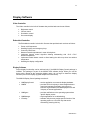
MW Manager
MWManager receives, shows and logs all display events. It displays hardware and software
versions, temperature and battery status. This software application provides basic
information about the display and selection of desired notifications on extreme conditions. To
run Display Manager, click the MW800 Display Manager icon on the Start menu.
This application provides the following information:
•
Versions - General information about Display hardware, embedded firmware and
software versions
•
Power - The Display current consumption and the voltage level of the vehicle battery
•
Temperature Real-time internal temperatures
•
Agent Notifications - alerts if one of the following event occurs
9 Internal temperature is beyond the operational limit.
If during operation the internal temperature is close to the low or high operational
limits, the display will provide critical temperature indication. If during operation
the internal temperature goes outside the operational limit, the display eventually
powers off.
6802982C85-C
9
Vehicle battery is discharged.
If, during normal operation, the battery voltage drops below the Low Battery
Threshold, the display will provide low battery indication and send the Low
Battery event to the CPU.
9
Drops in car battery voltage.
If battery voltage falls below the Critically Low Battery Threshold for 20 seconds
or more, the device will send a Cranking alert to the CPU, execute critical shut
down and power itself off.
26
•
9
Over-current event
If during normal operation, the current drain exceeds the Critical Current Drain
Threshold, the device will execute critical shut down and power itself off.
9
Over-voltage protection
If during normal operation, a level of the car battery voltage exceeds the Critically
High Battery Threshold, the device will execute critical shut down and power
itself off.
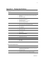
Logger
- troubleshooting tool for documentation of extreme events.
6802982C85-C
27
MW810 8.4” Display Owner’s Manual C
Display Adjustment
Display performance can vary due to the graphics card, host computer, lighting conditions
and other environmental factors. In order to get the best image on a monitor, some
adjustments may be required.
The MW810 display provides three options for image adjustment:
•
•
•
Proper setting of the timing mode (refresh rate and resolution)
Embedded On-Screen Display control
Windows On-Screen Display application
Setting the Timing Mode
Set proper video adapter timing mode to maximize the quality of the screen image. The
timing mode consists of the Resolution and Refresh Rate. Recommended screen resolution
is VESA 1024 by 768 pixels; recommended screen refresh rate is 60 Hz.
Set the screen resolution in Display Properties as follows: click the right mouse button at
desktop and select Properties Æ Settings. Select recommended resolution using the
Screen Resolution slider.
Set the screen refresh rate in Display Properties as follows: click the right mouse button at
desktop and select Properties Æ Settings Æ Advanced Æ Monitor. Select recommended
refresh rate in the Screen Refresh Rate field.
If after setting of the video adapter timing mode the quality of the screen image needs to be
improved, use Embedded or Windows On-Screen Display controls to adjust the screen
image.
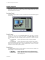
Embedded On-Screen Display Control
On-Screen Display (OSD) is a control panel on a display screen that allows you to select
viewing options and/or adjust components of the display, such as brightness, contrast,
horizontal and vertical positioning, etc. This section describes controls available to tune the
image via OSD menus.
The OSD panel includes control tabs for activation of different OSD features. In addition, the
MW810 OSD panel provides information about video input parameters as follows:
•
•
•
•
Resolution
Refresh frequency
Video Input: Analog or Digital (DVI)
The version of the LCD controller firmware
How to use the embedded on-screen display:
•
•
•
•
6802982C85-C
Push the OSD button located on the front display panel to activate the OSD control.
Long push (for 3 seconds or more) activates the Auto Adjust. That's valid only for
RGB video input.
Scroll through menu options.
When a specific OSD feature is selected, activate that feature by pushing of the
OSD button.
28
•
•
•
You can exit OSD any time by selection of the
tab. Also, the OSD control will be
automatically closed if the OSD button is inactive and the OSD time-out (factory
setting - 5 seconds) is elapsed.
Display saves the new OSD data after OSD menu closure.
OSD control keeps the Factory display settings. It can be restored if necessary.
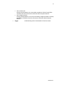
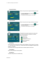
Main Menu
Allows selection viewing options and/or adjust components of the display.
Push the OSD button. The main OSD screen provides
the following options:
9
9
9
9
9
Volume
Video
Color
Display Adjust
Tools
Scroll to select desired feature.
Activate selected feature by pushing of the OSD button.
Volume Control
Allows adjusting a volume of sound from internal
speaker.
•
•
tab and push
From the main menu select the
the OSD button.
Scroll to set desired level of sound.
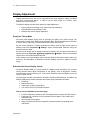
Video Control (Main Menu)
To activate video controls, from the main menu select the
tab and push the OSD button.
Available features are as follows:
Brightness
Contrast
LED Illumination
Night/Day view
Note: the Night/Day button allows toggling between Day and Night color palettes.
6802982C85-C
29
MW810 8.4” Display Owner’s Manual C
Note: if display's configuration allows automatic illumination control, manual adjustment of
the LED Illumination is disabled. In that case LED sign will be in grey color.
Brightness
Adjusts the background black level of the screen image
in order to keep details in darker image areas.
•
•
From the main Video Control menu select
the Brightness tab and push the OSD button.
Scroll to set desired brightness level.
Contrast
Adjusts the difference between the background black
and foreground white levels in order to keep details in
lighter image areas.
•
•
From the main Video Control menu select the
Contrast tab and push the OSD button.
Scroll to set desired contrast level.
LED Illumination
Allows to increase or decrease a level of illumination of
displays function keys, labels, and emergency key.
•
•
From the main Video Control menu select the
Illumination tab and push the OSD button.
Scroll to set desired illumination level.
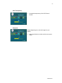
Color Control
Color control affects the overall color quality.
•
•
6802982C85-C
tab and push
From the main menu select the
the OSD button.
Select one of available features as shown next:
Color Temperature
30
Color Temperature
•
•
•
Color temperature is the point at which equal
combination of red, green, and blue colors create
white at full intensity.
The OSD provides a list the supported color
temperature presets. The display is capable of color
temperatures of 4200k, 5000k, 6500k, 7500k, and
9300k.
To obtain accurate color, brings up the White
Balance pattern and calibrate the output of your
graphics card to match the input of your display.
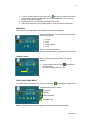
Display Adjust
To activate geometry controls, from the main menu
select the
tab and push the OSD button.
Available features are as follows:
Auto Adjust
Stretch
Horizontal position
Vertical position
Note: Geometry adjustments are available only at Analog Input.
Auto Adjust
Auto adjustment automatically sizes, centers, and tunes the video signal parameters in order
to eliminate image distortions. That's valid only for RGB video input.
Note: A dialog box appears when auto adjustment is done. Confirm auto adjustment result in
order to store the new set of parameters. Opposite, the display will restore the previous
configuration.
Stretch
Allows shrink/stretch the image area.
•
•
From the main Display menu select the Stretch tab
and push the OSD button.
Set desired size of the image.
6802982C85-C
31
MW810 8.4” Display Owner’s Manual C
Horizontal Position
Allows moving the screen image horizontally left or right.
•
•
tab and
From the main Display menu select the
push the OSD button.
Set desired horizontal position of the image.
Vertical Position
Allows moving the screen image vertically up and down.
•
•
•
From the main Display menu select the
push the OSD button.
Set desired vertical position of the image.
tab and
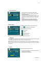
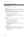
Tools
To activate Tools controls, from the main menu select
the Tools tab and push the OSD button. Available
features are as follows:
OSD setting
Factory Reset
OSD Pattern Generator
OSD Transparency
Sharpness
OSD Setting
OSD Timeout sets the time frame the OSD control is displayed. Factory setting is 5 seconds,
i.e. if the OSD button is inactive for 5 seconds the OSD control disappears. Maximal OSD
timeout is 15 seconds.
OSD Position allows moving the OSD control to another position at the screen.
Factory Reset
Resets OSD parameters to factory default.
OSD Patterns
Generate video patterns for troubleshooting.
6802982C85-C
32
OSD Transparency
•
Set desired transparency of the OSD Control
window.
Sharpness
Allows sharpening text, color and images on your
display.
•
Adjust the slider bar to clarify and focus the screen
image.
6802982C85-C
33
MW810 8.4” Display Owner’s Manual C
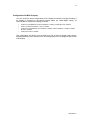
Mobile and Office Configurations
Display Configuration Tips
You can use the display either in Office or in Mobile modes.
Office Mode
In the office mode CPU and display work independently; changing in the CPU power state
does not have any impact on the display and vice versa. This mode is similar to a secondary
display connected to the laptop.
In the office mode the display shall be powered on and off from the power button located on
the display with no dependency on the CPU status. If there is no video from the CPU, the
display will stay in the Video Off state until video becomes active.
For the office display set configuration parameters as follows:
•
POWER UP PREFERENCES: USB 5V PRESENCE = DISABLE, POWER BUTTON = ENABLE
•
DISPLAY POWER UP OPTIONS = TURN ON
•
POWER OFF PREFERENCES: CPU REQUEST = DISABLE, USB 5V ABSENCE = DISABLE, POWER
BUTTON = ENABLE
•
POWER OFF EVENT = DISABLE
Mobile Mode
In the mobile mode there is synchronization of power states between the CPU and Display,
i.e.
•
•
If CPU is on, it will turn on the display and vice versa.
If CPU is off, it will turn off the display and vice versa.
For the mobile display set configuration parameters as follows:
•
POWER UP PREFERENCES: USB 5V PRESENCE = ENABLE, POWER BUTTON = ENABLE
•
DISPLAY POWER UP OPTIONS = WAIT or IGNORE
•
POWER OFF PREFERENCES: CPU REQUEST = ENABLE, USB 5V ABSENCE = ENABLE, POWER
BUTTON = ENABLE
•
POWER OFF EVENT = ENABLE
Disable Power Button
You may want to disable the display power button in order to prevent system shut down
when you press the display power button. Set configuration parameters as follows:
•
POWER OFF PREFERENCES: CPU REQUEST = DISABLE, USB 5V ABSENCE = ENABLE, POWER
BUTTON = DISABLE
•
POWER OFF EVENT = DISABLE
•
CRITICAL TURN OFF = DISABLE
6802982C85-C
34
Configuration for ML910 Laptop
You can use all the above configurations for the display connected to the ML910 laptop. If
the display is connected to the ML910 docking station (so called MODS option), it's
recommended to configure the display as follows:
•
POWER UP PREFERENCES: USB 5V PRESENCE = DISABLE, POWER BUTTON = ENABLE
•
DISPLAY POWER UP OPTIONS = WAIT or IGNORE
•
POWER OFF PREFERENCES: CPU REQUEST = ENABLE, USB 5V ABSENCE = DISABLE, POWER
BUTTON = ENABLE
•
POWER OFF EVENT = ENABLE
This configuration will allow to turn the ML910 on and off from the display power button.
Attaching/detaching of the ML910 to/from its docking station will not change the power state
of the display.
6802982C85-C
35
MW810 8.4” Display Owner’s Manual C
Display Upgrade
Use the MW810 Field Support CD-ROM when you need to install or update unique software
and firmware components. If your CPU box does not have CD-ROM or DVD drive, connect
USB CD-ROM drive to the CPU box.
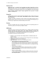
Description/Tutorial
Insert MW810 Support Kit CD into CD drive. The Main Menu screen automatically appears
as shown next:
Display Firmware
From the main menu, click on the Firmware Update button and follow the on-screen
instructions to continue and complete the process. The Firmware Update sub-menu
provides installation the CPU and Display firmware components. The choices are shown
next:
•
•
8.4" Display EC
controller
8.4" Display EC
- install or update firmware for the 8.4" Display embedded
- install or update firmware for the 8.4" Display video controller
Select desired firmware component and click on the appropriate button - the MW810 Field
Support kit will automatically install or replace selected firmware. Follow the on-screen
instructions to continue and complete the process.
Display Drivers
The Display Drivers sub-menu provides installation of several OS drivers related to the
MW810 display unit. The choices are shown next:
•
•
•
6802982C85-C
Touch Screen
USB-RS232
MW810 Utilities
- install or update the software driver for the Gunze touch panel
- install or update drivers for the TI3410 USB-RS232 adapter
- install or update the unique drivers and applications for MW810
CPU and display units
36
Select desired software component and click on the appropriate button - the MW810 Field
Support kit will automatically install or replace selected software. Follow the on-screen
instructions to continue and complete the process.
NOTE: Installation or update of the USB-RS232 driver requires manual user intervention.
See the MW810 Field Support Kit User's Manual for details.
Display Service
Generally, the display software service is already preinstalled. If it has not yet been installed,
you can reinstall by using of the MW810 Field Support Kit CD as follows:
The CPU Drivers sub-menu provides installation of several OS drivers related to the
MW810 CPU unit. Select MW810 software component and click on the appropriate button the MW810 Field Support kit will automatically install or replace the MW810 display service
and applications software. Follow the on-screen instructions to continue and complete the
process.
6802982C85-C
37
MW810 8.4” Display Owner’s Manual C
Getting Assistance
For your convenience, the Motorola website provides up-to-date information about the
MW810.
The Web address for the MW810 home page is www.motorola.com/MW810. This site
includes general information about the device, as well as answers to questions regarding
operational issues with the MW810.
For product-specific downloads search at https://compass.motorola.com/go/323749890. This
site provides as follows:
•
•
•
6802982C85-C
Recent software / application updates
Updated embedded firmware for your computer
The latest device drivers
38
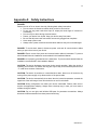
Appendix A: Safety Instructions
DANGER:
Reduce the risk of fire or electric shock by following basic safety instructions:
• Do not connect or disconnect cables while you device is turned on.
• Do not use any power cord where input or output pins show signs of corrosion or
overheating.
• Do not use your device during electrical storms.
• Protect your device from liquids. Keep your device away from water.
• Be sure that all power cord connections are securely plugged into receptions.
• Never wrap a power cord.
• Always route a power cord and communication cables so they will not be damaged.
DANGER: To avoid shock hazard, disconnect power cord and all communication cables
when you open the covers of your device.
DANGER: Electric current from power and communication cables is hazardous. To prevent
shock hazard follow the installation recommended in the Installation Manual.
DANGER: An improperly grounded device is hazardous. To prevent shock hazard follow the
installation recommended in the Installation Manual.
CAUTION: The device dissipates some heat during normal operation. When the device is
operating, do not leave it in contact with any part of your body for an extended period of time
– it could cause a sense of discomfort.
CAUTION: The device is sensitive to uncontrolled shut down. Never turn off the device by
turning off the power supply or by disconnection of the power cable.
CAUTION: The device automatically shuts down then the internal temperature exceeds the
upper limit of the valid range. Never turn the device on until it cools down.
CAUTION: Wrong configuration can make your device unworkable. Please, make sure to
acquire the appropriate codeplug. Always make a backup copy in case you have made a
mistake during the update.
CAUTION: Do not use right- and left-side USB ports for permanent connections. Always
disconnect USB accessories from these ports when driving.
6802982C85-C
39
MW810 8.4” Display Owner’s Manual C
Appendix B: Warranty Information
EPS – 34440- B
This warranty applies within the fifty (50) United States, the District of Columbia and Canada.
LIMITED WARRANTY
MOTOROLA COMMUNICATION PRODUCTS
If the affected product is being purchased pursuant to a written Communications System
Agreement signed by Motorola, the warranty contained in that written agreement will apply.
Otherwise, the following warranty applies.
I. WHAT THIS WARRANTY COVERS AND FOR HOW LONG:
Motorola Inc. or, if applicable, Motorola Canada Limited ("Motorola") warrants the Motorola
manufactured radio communications product, including original equipment crystal devices
and channel elements ("Product"), against material defects in material and workmanship
under normal use and service for a period of One (1) Year from the date of shipment.
Motorola, at its option, will at no charge either repair the Product (with new or reconditioned
parts), replace it with the same or equivalent Product (using new or reconditioned Product),
or refund the purchase price of the Product during the warranty period provided purchaser
notifies Motorola according to the terms of this warranty. Repaired or replaced Product is
warranted for the balance of the original applicable warranty period. All replaced parts of the
Product shall become the property of Motorola.
This express limited warranty is extended by Motorola to the original end user purchaser
purchasing the Product for purposes of leasing or for commercial, industrial, or governmental
use only, and is not assignable or transferable to any other party. This is the complete
warranty for the Product manufactured by Motorola. Motorola assumes no obligations or
liability for additions or modifications to this warranty unless made in writing and signed by
an officer of Motorola.
Unless made in a separate written agreement between Motorola and the original end user
purchaser, Motorola does not warrant the installation, maintenance or service of the Product.
Motorola cannot be responsible in any way for any ancillary equipment not furnished by
Motorola, which is attached to or used in connection with the Product, or for operation of the
Product with any ancillary equipment and all such equipment is expressly excluded from this
warranty. Because each system, which may use the Product, is unique, Motorola disclaims
liability for range, coverage, or operation of the system as a whole under this warranty.
II. GENERAL PROVISIONS:
This warranty sets forth the full extent of Motorola’s responsibilities regarding the Product.
Repair, replacement or refund of the purchase price, at Motorola’s option, is the exclusive
remedy.
THIS WARRANTY IS GIVEN IN LIEU OF ALL OTHER EXPRESS WARRANTIES.
MOTOROLA DISCLAIMS ALL OTHER WARRANTIES OR CONDITIONS, EXPRESS OR
IMPLIED, INCLUDING THE IMPLIED WARRANTIES OR CONDITIONS OF
MERCHANTABILITY AND FITNESS FOR A PARTICULAR PURPOSE. IN NO EVENT
SHALL MOTOROLA BE LIABLE FOR DAMAGES IN EXCESS OF THE PURCHASE PRICE
OF THE PRODUCT, FOR ANY LOSS OF USE, LOSS OF TIME, INCONVENIENCE,
COMMERCIAL LOSS, LOST PROFITS OR SAVINGS OR OTHER INCIDENTAL, SPECIAL,
INDIRECT OR CONSEQUENTIAL DAMAGES ARISING OUT OF THE USE OR INABILITY
TO USE SUCH PRODUCT, TO THE FULL EXTENT SUCH MAY BE DISCLAIMED BY
LAW.
6802982C85-C
40
III. HOW TO GET WARRANTY SERVICE:
Purchaser must notify Motorola’s representative or call Motorola’s Customer Response
Center at 1-800-247-2346 within the applicable warranty period for information regarding
warranty service.
IV. WHAT THIS WARRANTY DOES NOT COVER:
A) Defects or damage resulting from use of the Product in other than its normal and
customary manner.
B) Defects or damage from misuse, accident, water, or neglect.
C) Defects or damage from improper testing, operation, maintenance, installation, alteration,
modification, or adjustment.
D) Breakage or damage to antennas unless caused directly by defects in material
workmanship.
E) A Product subjected to unauthorized Product modifications, disassemblies or repairs
(including, without limitation, the addition to the Product of non-Motorola supplied equipment)
which adversely affect performance of the Product or interfere with Motorola’s normal
warranty inspection and testing of the Product to verify any warranty claim.
F) Product, which has had the serial number removed or made illegible.
G) Freight costs to the repair depot.
H) A Product, which, due to illegal or unauthorized alteration of the software/firmware in the
Product, does not function in accordance with Motorola’s published specifications or with the
FCC type acceptance labeling in effect for the Product at the time the Product was initially
distributed from Motorola.
I) Scratches or other cosmetic damage to Product surfaces that do not affect the operation of
the Product.
J) That the software in the Product will meet the purchaser’s requirements or that the
operation of the software will be uninterrupted or error-free.
K) Normal and customary wear and tear.
L) Non-Motorola manufactured equipment unless bearing a Motorola Part Number in the
form of an alphanumeric number (i.e., TDE6030B).
V. GOVERNING LAW
In the case of a Product sold in the United States and Canada, this Warranty is governed by
the laws of the State of Illinois and the Province of Ontario, respectively.
VI. PATENT AND SOFTWARE PROVISIONS:
Motorola will defend, at its own expense, any suit brought against the end user purchaser to
the extent that it is based on a claim that the Product or its parts infringe a United States
patent, and Motorola will pay those costs and damages finally awarded against the end user
purchaser in any such suit which are attributable to any such claim, but such defense and
payments are conditioned on the following:
A) that Motorola will be notified promptly in writing by such purchaser of any notice of such
claim;
B) that Motorola will have sole control of the defense of such suit and all negotiations for its
settlement or compromise; and
6802982C85-C
41
MW810 8.4” Display Owner’s Manual C
C) should the Product or its parts become, or in Motorola's opinion be likely to become, the
subject of a claim of infringement of a United States patent, that such purchaser will permit
Motorola, at its option and expense, either to procure for such purchaser the right to continue
using the Product or its parts or to replace or modify the same so that it becomes noninfringing or to grant such purchaser a credit for the Product or its parts as depreciated and
accept its return. The depreciation will be an equal amount per year over the lifetime of the
Product or its parts as established by Motorola. Motorola will have no liability with respect to
any claim of patent infringement which is based upon the combination of the Product or its
parts furnished hereunder with software, apparatus or devices not furnished by Motorola, nor
will Motorola have any liability for the use of ancillary equipment or software not furnished by
Motorola which is attached to or used in connection with the Product. The foregoing states
the entire liability of Motorola with respect to infringement of patents by the Product or any of
its parts thereof.
Laws in the United States and other countries preserve for Motorola certain exclusive rights
for copyrighted Motorola software such as the exclusive rights to reproduce in copies and
distribute copies of such Motorola software. Motorola software may be used only in the
Product in which the software was originally embodied and such software in such Product
may not be replaced, copied, distributed, modified in any way, or used to produce any
derivative thereof. No other use including, without limitation, alteration, modification,
reproduction, distribution, or reverse engineering of such Motorola software or exercise of
rights in such Motorola software is permitted. No license is granted by implication, estoppel
or otherwise under Motorola patent rights or copyrights.
6802982C85-C
42
Appendix C: Display Specifications
General
PARAMETER
DESCRIPTION
LCD
•
Type: 12.1" (12.1" viewable diagonal area),
•
Color filter : TFT active matrix XGA LCD, 0.294 mm pixel pitch, RGB
vertical stripe
•
Glass surface: Antiglare
•
Analog: RGB (75 ohms)
INPUT RGB SIGNAL
INPUT DVI SIGNAL
RESOLUTION
VIEWING ANGLE
ON-CHIP OSD
TOUCH SCREEN
FUNCTION KEYS
•
Up to SXGA 75Hz / UXGA 60Hz
•
Composite sync support
•
Input format detection and auto-alignment
•
Phase clock and image positioning
•
Up to UXGA 60Hz
•
Direct connect to all DVI-compliant digital transmitters
•
1024 × 768 @ 60 Hz
•
800 × 600 @ 60 Hz
•
640 × 480 @ 60 Hz
•
HB: V = 160°, H = 160°
•
SB: V = 120°, H = 100°
•
On-chip RAM for high-quality programmable menus
•
Auto image adjustment
•
Pattern generator
•
Resistive 8-wire active matrix
•
1024 × 1024 electrical resolution
•
Emergency button
•
8 programmable function keys
LOUDSPEAKER
•
One, 0.5W output
DIMENSIONS
292 x 270 x 49 mm
WEIGHT
•
HB – 3.12 kg
•
SB – 2.93 kg
Environmental Specifications
PARAMETER
DESCRIPTION
POWER SOURCE
•
Vehicle 12V, 24V battery, negative ground, with power loss
compensation during engine cranking
•
Vehicle 9V battery, negative ground, without power loss compensation
during engine cranking
•
13.8 VDC ± 20% with no loss of functionality for 12V battery
•
27.6 VDC ± 20% with no loss of functionality for 24V battery
POWER SOURCE STABILITY
6802982C85-C
43
MW810 8.4” Display Owner’s Manual C
•
9 VDC ± 10% with no loss of functionality for 9V battery
CAR BATTERY PROTECTION
•
Auto shut-down on low vehicle battery voltage to protect against
excessive drain
POWER CONSUMPTION
@ 13.8 VDC max
•
Maximal HB – 2.8A, SB – 1.5A (w/o heater), 4.5A (with heater)
•
Standby 0.4A
ELECTRICAL TRANSIENTS
Operational Electrical Transients Per ISO7637 (CE).
SAFETY
Operational Safety Per UL 60950-1, EN60950-1
STORAGE CONDITIONS
Temperature: -40 to 158˚F (-40 to +70˚C)
OPERATING CONDITIONS
Temperature: -22 to 158˚F (-30 to +70˚C) with controlled brightness
Humidity: 90 to 95% Relative humidity at 50˚C for 8 hours
THERMAL SHOCK
-40 to 158˚F (-40 to +70˚C)
MECHANICAL SHOCK
20G peak 1/2 sine wave @ 11ms, 30 impacts
VIBRATION
MIL-STD-810F Method 514.5 category 4 Fig. 514.5c-1 1 hour axis.
IP RATING FOR
DUST/WATER
IP 54
DRIP
Per MIL-STD 810F method 506.4 procedure III
DUST BLOWING
5 hours in dust (140 mesh silica flour), laden atmosphere, dust agitation time
is for 2 seconds every 15 minutes
SALT FOG
8 hours, 5% Sodium Chloride at 35˚C per MIL-STD-810F 509.4, procedure I
FLAMMABILITY
UL94-V0
SOLAR RADIATION
7 cycles of 24 hours with no functional degradation per MIL-STD-810F,
505.4, Procedure I
IMPACT
Ball drop test 130gr. Steel ball from 0.5 m height.
SHOCK CRASH HAZARD
75G, 6 ms per MIL-STD-810F method 516.5, Procedure V
ALTERNATOR WHINE:
Per Motorola’s 12M05049A04
REVERSE POLARITY
Per Motorola’s 12M05049A04
CRANKING
Per Motorola’s 12M05049A04
ESD
Per Motorola’s 12M05049A04 ESD Procedure
RADIATED IMMUNITY
20V/m EN 61000-4-3
Regulations
TEST
STANDARD
eMARK
Directive 72/245EC (94/95EC)
EMC IMMUNITY
•
USA - EN301-489, receive full EMC certification relevant to mobile
computing device
•
Canada - ICES003 (equivalent to FCC Part 15, Class B)
•
Europe – CE EN55024
•
USA - FCC Part 15 class B #247, BQB qualification for Bluetooth
•
Canada - RSS210, RSS119, RSS 132, RSS133
•
Europe – CE EN55022
•
Australia - AS/NZS 3548
•
USA - UL
•
Canada - UL
RADIATED EMISSION
SAFETY
6802982C85-C
44
•
FCC ID's
Europe - EN60950
Bluetooth radio
FCC ID: QDS-BRCM1018
IC: 4324A-BRCM1018
Display Thresholds
THRESHOLD
VALUE
Low Display Temperature Threshold
Equivalent to -25°C ambient
High Display Temperature Threshold
Equivalent to +65°C ambient
Critically Low Display Temperature Threshold
Equivalent to -30°C ambient
Critically High Display Temperature Threshold
Equivalent to +70°C ambient
Low Battery Threshold
10.2VDC
Critically Low Battery Threshold
7.0VDC
Critically High Battery Limit
35VDC
Critical Current Consumption Limit
12A
Heater Low Threshold
0°C
Heater High Threshold
5°C
6802982C85-C
45
MW810 8.4” Display Owner’s Manual C
Appendix D: Troubleshooting Information
You can solve many problems without outside assistance by following the troubleshooting
procedures that MW810 provides in the online help or in the documents that are provided
with the device, operating system and software applications. Most software applications
come with description containing troubleshooting procedures and explanation of error
information. If you suspect a software issue, refer the information for the operating system or
application programs.
NOTE: This manual does not cover operating system issues. For operation system
directions, refer to Microsoft Windows XP or Windows 7 documentation.
This chapter contains helpful hints to follow when you encounter any problem. If a problem
persists after you follow the instructions in this chapter, contact your system administrator for
help.
If you see
Do as follows
Display is powered on but the Power LED is
off
•
Make sure Power supply cable is securely connected
•
Make sure the main CPU power switch is on
Display is powered on but there is no screen
image
•
Make sure the system is not in standby mode
•
Make sure video cable is securely connected
•
Adjust the brightness and/or contrast
•
Check the video cable to be sure it's securely connected
•
Check colors using pattern generator (see the Display
Adjustments chapter).
•
Use OSD controls to adjust color settings.
Abnormal colors
Temperature LED is steady red.
The internal temperature is high. Never turn on the device until it
cools down to normal operating temperature.
Temperature LED blinks red
Display temperature is out of operational range. Wait until
temperature heats up / cools down to normal.
Over current is detected in device connected
to USB port.
Please, disconnect the USB device – its current consuming is
more than 0.5A.
The image is too light or dark.
Use display OSD controls to adjust the brightness and contrast.
No sound or minimal volume.
•
Make sure the sound driver is properly installed
•
Make sure the speaker codeplug setting is UNMUTE
•
Adjust the volume
No screen image on the primary display.
Press CTRL-ALT-F1
No screen image on the secondary display.
Press CTRL-ALT-F12 and define the video mode for the
secondary display
Cannot turn the device off, the system does
not respond
Turn off the device by pressing and holding the power button for
6 seconds or more. Use either CPU or display power buttons.
6802982C85-C
46
Appendix E: Acronyms and Abbreviations
The following acronyms and abbreviations are used in this document:
API
Application Programming Interface
CCFL
Cold Cathode Fluorescent Lamp
CD
Compact Disk
CD-ROM
Compact Disk Read-Only Memory
CPU
Central Processor Unit
DDC/CI
Display Data Channel Command Interface
DLL
Dynamic Link Library
DTE
Data Terminal Equipment
DVD
Digital Versatile Disc
DVI
Digital Visual Interface
EME
Electromagnetic Emission
FAQ
Frequently Asked Questions
FCC
Federal Communications Commission
GPIO
General Purpose Input Output
HB
High Brightness
HID
Human Interface Device
LCD
Liquid Crystal Display
LED
Light-Emitting Diode
MB
Megabit
MODS
Mobile Office Dock Solution
MPS
Maintenance Programming Software
ML
Mobile Laptop
MW
Mobile Workstation
NIT
Near Infrared Transmission
OSD
On-Screen Display
RGB
shorthand for Red, Green, Blue
RF
Radio Frequency
SB
Standard Brightness
SDK
Software Development Kit
TFT
Thin Film Transistor
USB
Universal Serial Bus
VDC
Volts Direct Current
VESA
Video Electronics Standard Association
WHQL
Windows Hardware Quality Lab
WLAN
Wireless Local Area Network
XGA
eXtended Video Graphics Array
6802982C85-C
47
MW810 8.4” Display Owner’s Manual C
Technology that’s second nature™
Motorola, Inc.
1301 E. Algonquin Road,
Schaumburg, IL 60196 U.S.A.
Inside the USA, Americas and Canada, call Motorola System Support Center at 1-800 221-7144
For Europe, the Middle East and Africa, call +420 533 336 123
MOTOROLA and the Stylized M Logo are registered in the U.S. Patent and Trademark Office. All
other product or service names are the property of their respective owners. © Motorola, Inc. 2010.
6802982C85-C