1
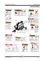
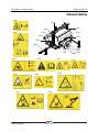
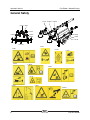
Operator's Manual AL4 AL5 ANSI/CSA North America South America Asia with Maintenance Information First Edition Second Printing Part No. 229100 Operator's Manual First Edition • Second Printing Front Matter Important Contents Read, understand and obey these safety rules and operating instructions before operating this machine. Only trained and authorized personnel shall be permitted to operate this machine. This manual should be considered a permanent part of your machine and should remain with the machine at all times. If you have any questions, contact us. Introduction ........................................................... 1 Symbol and Hazard Pictorials Definitions ............. 3 General Safety ...................................................... 5 Work Area Safety .................................................. 9 Legend ................................................................ 15 Controls ............................................................... 16 Inspections .......................................................... 20 Operating Instructions ......................................... 32 Transport and Lifting Instructions ....................... 37 Maintenance ....................................................... 39 Specifications ...................................................... 42 Reporting Safety Defects .................................... 43 Contact Us: Internet: www.terex.com E-mail: [email protected] Copyright © 2011 Terex Corporation First Edition: Second Printing, February 2013 "Terex" is a registered trademark of Terex USA, LLC in the USA and many other countries. These machines comply with ANSI/SIA A92.5 CAN B.354.4 AL4 • AL5 Part No. 229100 First Edition • Second Printing Operator's Manual Introduction Introduction Owners, Users and Operators: Thank you for choosing our machine for your application. Our number one priority is user safety, which is best achieved by our joint efforts. We feel that you make a major contribution to safety if you, as the equipment users and operators: Danger 1 Comply with employer, job site and governmental rules. 2 Read, understand and follow the instructions in this and other manuals supplied with this machine. 3 Use good safe work practices in a commonsense way. 4 Only have trained/certified operators, directed by informed and knowledgeable supervision, running the machine. Failure to obey the instructions and safety rules in this manual will result in death or serious injury. Do Not Operate Unless: You learn and practice the principles of safe machine operation contained in this operator’s manual. 1 Avoid hazardous situations. Know and understand the safety rules before going on to the next section. 2 Always perform a pre-operation inspection. 3 Always perform function tests prior to use. 4 Inspect the workplace. 5 Only use the machine as it was intended. You read, understand and obey the manufacturer’s instructions and safety rules—safety and operator’s manuals and machine decals. You read, understand and obey employer’s safety rules and worksite regulations. You read, understand and obey all applicable governmental regulations. You are properly trained to safely operate the machine. Part No. 229100 AL4 • AL5 1 Operator's Manual First Edition • Second Printing Introduction Hazard Classification Intended Use Decals on this machine use symbols, color coding and signal words to identify the following: This machine is intended to be used only to provide lighting and electrical power to a work site. Safety alert symbol—used to alert you to potential personal injury hazards. Obey all safety messages that follow this symbol to avoid possible injury or death. DANGER Indicates a hazardous situation which, if not avoided, will result in death or serious injury. Safety Sign Maintenance Replace any missing or damaged safety signs. Keep operator safety in mind at all times. Use mild soap and water to clean safety signs. Do not use solvent-based cleaners because they may damage the safety sign material. WARNING Indicates a hazardous situation which, if not avoided, could result in death or serious injury. CAUTION NOTICE 2 Indicates a hazardous situation which, if not avoided, could result in minor or moderate injury. Indicates a property damage message. AL4 • AL5 Part No. 229100 First Edition • Second Printing Operator's Manual Symbol and Hazard Pictorials Definitions Symbol and Hazard Pictorials Definitions Read the operator’s manual. Electrocution hazard. Stop engine. Earth ground. Electrocution hazard. Maintain required clearance. Electrocution/ Burn hazard. Disconnect the batteries. Read service manual. Crush hazard. Keep away from moving parts. Keep away from moving parts. Stay clear of belts and fan. Burn hazard. Explosion/ Burn hazard. Corrosive acid. Explosion hazard. Do not use ether or other high energy starting aids on machines equipped with glow plugs. No smoking. No open flame. No open flame. Part No. 229100 AL4 • AL5 3 Operator's Manual First Edition • Second Printing Symbol and Hazard Pictorials Definitions Burn hazard. Burn hazard. Burn hazard. Stay clear of hot exhaust. Stay clear of hot surfaces. Burn hazard, hot components. Stay clear of hot surfaces under cover. Carbon Monoxide hazard. Wear protective clothing. Shattering glass hazard. Crushing hazard. Stay clear of descending tower. Tip-over hazard. Deploy outriggers before raising mast. Tip-over hazard, tow speed. Lifting eye. Tie-down point. 4 AL4 • AL5 Part No. 229100 First Edition • Second Printing Operator's Manual General Safety 228712 228711 General Safety 97675 228711 133148 228711 133482 97675 133148 97602 97666 228712 133484 97666 114258 133482 114431 228708 133483 228708 97602 133484 114258 114431 Part No. 229100 133483 AL4 • AL5 5 Operator's Manual First Edition • Second Printing General Safety 161699 T108022 133483 161699 T108022 114431 133483 T108021 T108021 133148 114431 133148 6 AL4 • AL5 Part No. 229100 First Edition • Second Printing Operator's Manual General Safety 229782 229782 133042 229782 229781 82481 133149 229781 82487 229781 116893 114251 116894 133065 116895 82487 116893 133042 82481 Part No. 229100 114251 133149 133065 116895 116894 AL4 • AL5 7 Operator's Manual First Edition • Second Printing General Safety 161700 T108024 T108023 133149 82472 114391 133066 133065 133055 82481 116894 133149 back view 82472 82481 133066 161700 114391 T108023 133055 133149 133065 116894 T108024 8 AL4 • AL5 Part No. 229100 First Edition • Second Printing Operator's Manual Work Area Safety Work Area Safety Electrocution Hazards This machine is not electrically insulated and will not provide protection from contact with or proximity to electrical current. Obey all local and governmental regulations regarding required clearance from electrical power lines. At a minimum, the required clearance contained in the chart below must be followed. Line Voltage Required Clearance 0 to 50KV 10 ft 3.05 m 50 to 200KV 15 ft 4.60 m 200 to 350KV 20 ft 6.10 m 350 to 500KV 25 ft 7.62 m 500 to 750KV 35 ft 10.67 m 750 to 1000KV 45 ft 13.72 m Allow for mast movement, electrical line sway or sag, and beware of strong or gusty winds. Do not connect wires directly to the generator. Connect auxiliary equipment only to the power outlets provided. Do not perform service or replace the lamps with the engine/generator running or batteries connected. This machine should be grounded in accordance with all local electrical codes. Consult the local electrical codes or authority having jurisdiction in the area where the machine will be used for specific requirements. There is a permanent conductor between the generator (static winding) and the frame. Explosion and Fire Hazards Do not start the engine if you smell or detect liquid petroleum gas (LPG), gasoline, diesel fuel or other explosive substances. Do not operate the machine during lightning or storms. Do not refuel the machine with the engine running. Do not use the machine as a ground for welding. Do not refuel the machine while it is hot. Allow to cool for several minutes before refueling. Keep away from the machine if it contacts energized power lines. Personnel must not touch or operate the machine until energized power lines are shut off. Do not spill fuel inside the engine compartment. Refuel the machine and charge the battery only in an open, well-ventilated area away from sparks, flames and lighted tobacco. Do not operate the machine in hazardous locations or locations where potentially flammable or explosive gases or particles may be present. Do not spray ether into engines equipped with glow plugs. Part No. 229100 AL4 • AL5 9 Operator's Manual First Edition • Second Printing Work Area Safety Tip-over Hazards Crushing Hazard Do not lower the mast unless the area below is clear of personnel and obstructions. Do not raise the mast unless all outriggers are properly deployed, the foot pads are in firm contact with the ground and the machine is level. Keep hands hands and fingers away from any potential pinch points. Do not set the machine up on a surface where it cannot be leveled using only the leveling jacks. Do not lower the mast until the mast is retracted and the upper retaining bar is locked into the mast. No red should be visible on the mast. Do not hang objects from the lights or the mast. Do not use the mast to raise material or personnel. Do not move the machine unless the mast is lowered to the horizontal position. Do not raise the mast when wind speeds may exceed 62 mph / 100 km/h. Do not alter or disable machine components that in any way affect safety and stability. Collision Hazards Check the work area for overhead obstructions or other possible hazards. Do not adjust or stow the outriggers when the mast is raised. Be sure the tires are in good condition and the lug nuts tightened. Do not place ladders or scaffolds against any part of the machine. Burn Hazards Do not touch the lamp fixtures while they are turned on. Turn the lamps off and allow them to cool before touching. Do not touch hot parts of the engine or tailpipe, Use protective gloves when handling hot parts. Do not use the machine on a moving or mobile surface or vehicle. 10 AL4 • AL5 Part No. 229100 First Edition • Second Printing Operator's Manual Work Area Safety Fall Hazards Bodily Injury Hazard Do not use the machine indoors unless properly ventilated. Do not climb or stand on any part of the light tower. Traffic Hazards Do not breath exhaust fumes. Do not work on this equipment when mentally or physically fatigued. Stand clear of traffic when starting or checking the unit along the road. Do not work on this equipment when under the influence of drugs or alcohol. Damaged Machine Hazards Stay clear of belts and fan when engine is running. Do not use a damaged or malfunctioning machine. Do not use the machine if the protective barrier on any of the lamps is broken or punctured. Metal halide lamps produce shortwave ultra-violet radiation and can cause serious skin burns or eye inflammation if the protective barrier is not in place. Do not use a machine with a worn, frayed, kinked or damaged cable. Do not use where people will remain close to the lamps for more than a few minutes unless adequate shielding or other safety precautions are used. Stay clear of moving mast. Do not grasp the cable. Use proper lifting techniques when lifting and positioning the tongue of the machine. Always replace the protective lamp cover after replacing the lamp bulbs. Part No. 229100 Conduct a thorough pre-operation inspection of the machine and test all functions before each work shift. Immediately tag and remove from service a damaged or malfunctioning machine. Be sure all maintenance has been performed as specified in this manual and the appropriate Terex service manual. Be sure the operator's manual is complete, legible and in the storage container located on the machine. Be sure all decals are in place and legible. Do not modify or alter the light tower without the prior written permission of the manufacturer. AL4 • AL5 11 Operator's Manual First Edition • Second Printing Work Area Safety Component Damage Hazards Do not turn the lights on unless the engine is running. Always turn the lights off before shutting down the engine. Battery Safety Burn Hazards Batteries contain acid. Always wear protective clothing and eye wear when working with batteries. Do not tow the light tower while the lamps are hot. Hot lamps will break if moved. Do not replace lamp bulbs with any bulbs other than those specified on the machine and in this manual. Avoid spilling or contacting battery acid. Neutralize battery acid spills with baking soda and water. Note: Lamp bulbs contain mercury (Hg). Dispose of lamp bulbs according to local, state and federal laws. Be sure lamp fixture connections are properly tightened before turning lights on. Do not use any battery charger greater than 12V to charge the battery. Do not remove the vent caps from the battery when charging. Do not expose the batteries or the charger to water or rain during charging. Explosion Hazards Keep sparks, flames and lighted tobacco away from batteries. Batteries emit explosive gas. Do not contact the battery terminals or the cable clamps with tools that may cause sparks. 12 AL4 • AL5 Part No. 229100 First Edition • Second Printing Operator's Manual Work Area Safety Electrocution/Burn Hazards Towing Hazards Avoid contact with electrical terminals. Inspect the power cord for damage prior to each use. Replace any damaged cord before operating. Do not allow the power cord to become caught or crushed while raising, lowering or rotating the mast. Avoid electrical shock from contact with battery terminals. Remove all rings, watches and other jewelry. Read, understand and obey all of your tow vehicle manufacturer's recommendations, warnings and instructions before towing this machine. Do not tow the machine unless the mast is retracted and lowered to the horizontal position and the travel lock pin is secured. Do not tow the machine unless all outriggers have been retracted and stowed. Do not overload your tow vehicle. Check the manufacturer's Gross Vehicle Weight Rating (GVWR). To obtain the gross vehicle weight, add the tongue weight of the trailer to the vehicle weight (including vehicle, passengers and cargo). Lifting Hazard Use the appropriate number of people and proper lifting techniques when lifting the batteries. Do not load cargo on the machine. The light tower is not designed to carry any extra cargo. Be sure the hitch is securely attached to the tow vehicle. Be sure the safety chains (if required) are securely attached to the tow vehicle. Be sure that all driving lights are operational. Be sure all hitch components, lights and mirrors and methods of attaching the trailer to the tow vehicle conform to local, state and federal regulations. Do not tow the machine on public roads unless it meets all governmental regulations for towing. Do not exceed 60 mph / 97 km/h. Obey all local and national towing speed laws. Be sure to chock the wheels when parking on a hill. Use extreme care and slow speeds while towing across uneven terrain, debris, holes or drop-offs. Note: Do not tow machine when engine is running! This can cause severe engine/radiator damage and WILL NOT BE COVERED UNDER WARRANTY! Part No. 229100 AL4 • AL5 13 Operator's Manual First Edition • Second Printing Work Area Safety Lockout After Each Use When leaving the machine unattended, secure from unauthorized use. Unauthorized personnel may attempt to operate the machine without proper instruction, creating an unsafe condition. 14 AL4 • AL5 Part No. 229100 First Edition • Second Printing Operator's Manual Legend Legend 1 2 3 Tongue leveling jack Tongue with trailer hitch Air shutoff system Emergency Stop button (if equipped with automatic air shutoff system) 4 Upper retaining bar 5 Air shutoff system pull handle (if equipped with manual air shutoff system) 6 T-handle for mast rotation 7 Tie-downs 8 Mast 9 Forklift pockets 10 Curb side door 11 Ballast (located inside cabinet) Part No. 229100 12 Flashing beacon (if equipped with auto-start system) 13 Lifting eye 14 Green stripe 15 Red stripe 16 Lamps 17 Travel lock pin 18 Road side door 19 Outrigger 20 Control panel (located inside cabinet) 21 Raise/lower winch (for models with manual winch) 22 Lower retaining bar AL4 • AL5 15 Operator's Manual First Edition • Second Printing Controls Controls 4 2 1 AL4 6 1 2 4 3 HOURS 3 7 120V BREAKER 5 8 9 240V/30A L6-30R 120V/20A 5-20R AL5 8kW 5 4 6 3 HOURS 2 1 2 5 6 3 4 10 7 8 1 16 9 AL4 • AL5 Part No. 229100 First Edition • Second Printing Operator's Manual Controls 7 Control Panel 1 T-lock receptacle, 240V/30A 2 Light switches Turn the ignition switch to the prime position and hold the engine prime button down to prime the engine. Move each light switch up to turn on the indicated light. Move each light switch down to turn off the indicated light. On models with 6 lights, the switches marked 1/5 and 2/6 turn on 2 lights each. On models with 4 lights, each switch turns on one light. 3 Circuit breaker for GFI receptacle 4 Main circuit breaker Move the main circuit breaker switch up on the control panel before turning the individual light switches on or before attempting to use the convenience receptacles. 5 Hold the prime button down and turn the ignition switch to the start position to start the engine. Turn the ignition switch to the off position to turn the engine off. 8 Hour meter 9 Alternator failure light Light on indicates that the engine's DC alternator isn't producing enough voltage. 10 Raise/lower switch (if equipped with electric winch) The hour meter displays the number of hours the machine has operated. Part No. 229100 Engine prime button With the ignition switch in the run position, press and hold the prime button for 15 seconds before starting the engine. Release the prime button when the engine starts. Duplex receptacle with GFI, 120V/20A Convenience duplex receptacle with Ground Fault Interrupter (GFI). 6 Ignition switch for engine AL4 • AL5 Move the switch up to raise and extend the mast. Move the switch down to retract and lower the mast. 17 Operator's Manual First Edition • Second Printing Controls AL5 12kW & 20kW 8 1 2 5 6 3 4 9 HOURS 7 10 11 12 6 5 13 AL5 external panel 6 5 4 4 3 2 2 1 2 T-lock receptacle, 240V/30A Control Panel 3 T-lock receptacle, 20 kW external panel only 1 4 Circuit breaker for twist-lock receptacle 18 Circuit breaker for twist-lock receptacle, 20 kW external panel only AL4 • AL5 Part No. 229100 First Edition • Second Printing Operator's Manual Controls 5 Duplex receptacle with ground Fault Interrupter GFI 10 Raise/lower switch (if equipped with electric winch) 6 Circuit breaker for duplex receptacle 7 Light switches Move the switch up to raise and extend the mast. Move the switch down to retract and lower the mast. Move each light switch up to turn on the indicated light. Move each light switch down to turn off the indicated light. On models with 6 lights, the switches marked 1/5 and 2/6 turn on 2 lights each. On models with 4 lights, each switch turns on one light. 8 Turn the ignition switch to the prime position and hold the engine prime button down to prime the engine. Hold the prime button down and turn the ignition switch to the start position to start the engine. Main circuit breaker Move the main circuit breaker switch up on the control panel before turning the individual light switches on or before attempting to use the convenience receptacles. 9 11 Ignition switch for engine Turn the ignition switch to the off position to turn the engine off. 12 Engine prime button Hour meter With the ignition switch in the run position, press and hold the prime button for 15 seconds before starting the engine. Release the prime button when the engine starts. The hour meter displays the number of hours the machine has operated. 13 Alternator failure light Light on indicates that the engine's DC alternator isn't producing enough voltage. Part No. 229100 AL4 • AL5 19 Operator's Manual First Edition • Second Printing Inspections Inspections Pre-operation Inspection Fundamentals It is the responsibility of the operator to perform a pre-operation inspection and routine maintenance. Do Not Operate Unless: You learn and practice the principles of safe machine operation contained in this operator’s manual. 1 Avoid hazardous situations. 2 Always perform a pre-operation inspection. The pre-operation inspection is a visual inspection performed by the operator prior to each work shift. The inspection is designed to discover if anything is apparently wrong with a machine before the operator performs the function tests. The pre-operation inspection also serves to determine if routine maintenance procedures are required. Only routine maintenance items specified in this manual may be performed by the operator. Refer to the list on the next page and check each of the items. Know and understand the pre-operation inspection before going on to the next section. 3 Always perform function tests prior to use. 4 Inspect the workplace. 5 Only use the machine as it was intended. If damage or any unauthorized variation from factory delivered condition is discovered, the machine must be tagged and removed from service. Repairs to the machine may only be made by a qualified service technician, according to the manufacturer’s specifications. After repairs are completed, the operator must perform a pre-operation inspection again before going on to the function tests. Scheduled maintenance inspections shall be performed by qualified service technicians, according to the manufacturer’s specifications and the requirements listed in the responsibilities manual. 20 AL4 • AL5 Part No. 229100 First Edition • Second Printing Operator's Manual Inspections Winch Pre-operation Inspection Nuts, bolts and other fasteners Be sure that the operator’s manual is complete, legible and in the storage container located on the machine. Lamp fixtures, connections and bulbs Cable (kinks, frays and abrasions) Be sure that all decals are legible and in place. See Inspections section. Safety chains Engine and related components Check for engine oil leaks and proper fluid level. Add oil if needed. See Maintenance section. Fuel tanks Generator Check for engine coolant leaks and proper coolant level. Add coolant if necessary. See Maintenance section. Check entire machine for: Cracks in welds or structural components Check for battery fluid leaks and proper fluid level. Add distilled water if needed. See Maintenance section. Dents or damage to machine Excessive rust, corrosion or oxidation Check for proper tire pressure and lug nut torque. Add air to tires if needed. See Maintenance section. Be sure that all structural and other critical components are present and all associated fasteners and pins are in place and properly tightened. Check the following components or areas for damage, improperly installed or missing parts and unauthorized modifications: Be sure the that the battery is in place and properly connected. Electrical components, wiring and electrical cables After you complete your inspection, be sure that all compartment covers are in place and latched. Mast components Mast locking pins Latches and pins Tires and wheels Trailer lights and reflectors Outriggers, leveling jacks and foot pads Part No. 229100 AL4 • AL5 21 Operator's Manual First Edition • Second Printing Inspections Function Test Fundamentals The function tests are designed to discover any malfunctions before the machine is put into service. The operator must follow the step-by-step instructions to test all machine functions. Do Not Operate Unless: You learn and practice the principles of safe machine operation contained in this operator’s manual. 1 Avoid hazardous situations. 2 Always perform a pre-operation inspection. A malfunctioning machine must never be used. If malfunctions are discovered, the machine must be tagged and removed from service. Repairs to the machine may only be made by a qualified service technician, according to the manufacturer’s specifications. After repairs are completed, the operator must perform a pre-operation inspection and function tests again before putting the machine into service. 3 Always perform function tests prior to use. Know and understand the function tests before going on to the next section. 4 Inspect the workplace. 5 Only use the machine as it was intended. 22 AL4 • AL5 Part No. 229100 First Edition • Second Printing Operator's Manual Inspections 9 Function Tests Setup 10 Ground the light tower according to your local electrical code. A grounding rod is supplied inside the cabinet and a grounding lug is provided on the front of the machine, near the bottom. 1 Position the light tower at the desired work site. 2 Chock the wheels. 3 Disconnect the trailer lights and the safety chains. 4 Open the latch on the trailer hitch. 5 Pull the release pin on the tongue jack and rotate into place. 6 Turn the leveling jack handle to lower the front outrigger foot pad and raise the tongue of the machine enough to clear the tow vehicle. 7 Release the spring pin on the side outriggers and slide them out into the deployed position. Make sure the outriggers are locked in place. Rotate the leveling jack into position. Note: the outriggers are not designed to lift the tires of the unit off the ground. 8 Turn the leveling jack handles to level the machine. Level the machine using only the leveling jacks Note: the outriggers are not designed to lift the tires of the unit off the ground. Check the bubble level (if equipped) on the front of the machine to make sure the machine is level. Note: This machine should be grounded in accordance with all local electrical codes. Consult the local electrical codes or authority having jurisdiction in the area where the machine will be used for specific requirements. Test Machine Functions (models with manual winch) By raising and extending, then retracting and lowering the mast back to the horizontal position, the following functions will be tested: winches, latches, mast extension and mast rotation. 11 Remove the retaining pin and travel lock from the top of the mast. 12 Turn the raise/lower winch handle clockwise until the mast raises approximately 2 feet / 60 cm. Result: A clicking sound should be heard as the mast raises. 13 Release the winch handle. Result: The winch brake should hold the mast. Part No. 229100 AL4 • AL5 23 Operator's Manual First Edition • Second Printing Inspections 14 Continue to raise the mast until the lower retaining bar locks into the mast. 22 Rotate the mast to line up the arrows on the front of the mast. Result: The mast sections should raise smoothly, free of hesitation or binding. 23 Tighten the T-handle to secure the mast. 24 Attempt to rotate the mast in both directions. 15 Insert the retaining pin through the lower retaining bar. Result: The mast should not rotate. 16 Remove the retaining pin and pull the upper retaining pin out. 25 Turn the winch handle counterclockwise until the upper retaining bar locks into the mast and no red line is visible on the mast. 17 Turn the extend/retract winch handle clockwise until the mast extends approximately 2 feet / 60 cm. Result: A clicking sound should be heard as the mast extends. 18 Release the winch handle. Result: The winch brake should hold the mast. 19 Continue to extend the mast until the mast reaches full vertical position. Stop extending the mast when the red line is visible on the mast. Result: The mast should extend smoothly, free of hesitation or binding. Result: No clicking sound should be heard when the winch handle is turned. 26 When the mast sections are fully retracted, pull the lower retaining bar. 27 Begin lowering the mast to the horizontal position by turning the raise/lower winch handle counterclockwise. Result: No clicking sound should be heard when the winch handle is turned. 28 Turn the winch handle counterclockwise until the mast is lowered into the travel lock. 29 Insert the travel lock pin and the retaining pin. 20 Turn the T-handle to release the mast location lock. 21 Rotate the mast clockwise and then counterclockwise as far as it will go in either direction. Result: The mast should rotate smoothly and easily in both directions. 24 AL4 • AL5 Part No. 229100 First Edition • Second Printing Operator's Manual Inspections Test Machine Functions (models with electric winch) 40 Turn the T-handle to release the mast location lock. 30 Remove the retaining pin and travel lock from the top of the mast. 41 Rotate the mast clockwise and then counterclockwise as far as it will go in either direction. 31 Move the raise/lower switch up until the mast raises approximately 2 feet / 60 cm. Result: The mast sections should raise smoothly, free of hesitation or binding. Result: The mast should rotate smoothly and easily in both directions. 42 Rotate the mast to line up the arrows on the front of the mast. 32 Release the raise/lower switch. Result: The winch brake should hold the mast. 33 Continue to raise the mast until the lower retaining bar locks into the mast. 43 Tighten the T-handle to secure the mast. 44 Attempt to rotate the mast in both directions. Result: The mast should not rotate. Result: The mast should raise smoothly, free of hesitation or binding. 34 Insert the retaining pin through the lower retaining bar. 35 Remove the retaining pin and pull the upper retaining pin out. 36 Move the raise/lower switch up until the mast extends approximately 2 feet / 60 cm. Result: The mast should extend smoothly, free of hesitation or binding. 37 Release the raise/lower switch. 38 Result: The winch brake should hold the mast. 39 Continue to extend the mast until the mast reaches full vertical position. Stop extending the mast when the red line is visible on the mast. 45 Move the raise/lower switch down until the upper retaining bar locks into the mast and no red line is visible on the mast. Result: The mast should retract smoothly, free of hesitation or binding. 46 When the mast sections are fully retracted, pull the lower retaining bar. 47 Begin lowering the mast to the horizontal position by moving the raise/lower switch down. 48 Result: The mast sections should lower smoothly, free of hesitation or binding. 49 Lower the mast until the mast is resting in the travel lock. 50 Insert the travel lock pin and the retaining pin. Result: The mast should extend smoothly, free of hesitation or binding. Part No. 229100 AL4 • AL5 25 Operator's Manual First Edition • Second Printing Inspections Test the Lights 51 Make sure the circuit breakers and the light switches are in the off position. Note: Be sure the lamp fixture connections are properly tightened before turning the lights on. 52 Start the engine. See Starting the Engine in the Operating Instructions section. 53 Turn the main circuit breakers to the on position. 54 Turn the light switches to the on position. Result: The lights should come on. Note: It can take up to 20 minutes for the lights to reach full intensity. If the lights are turned off and turned back on while they are still warm, they will not light up again for 20-30 minutes. Note: Make sure the circuit breaker and the light switches are turned off before shutting down the engine. 26 AL4 • AL5 Part No. 229100 First Edition • Second Printing Operator's Manual Inspections Workplace Inspection Checklist Be aware of and avoid the following hazardous situations: drop-offs or holes bumps, floor obstructions or debris Do Not Operate Unless: sloped surfaces You learn and practice the principles of safe unstable or slippery surfaces machine operation contained in this operator’s manual. overhead obstructions and high voltage conductors 1 Avoid hazardous situations. hazardous locations 2 Always perform a pre-operation inspection. inadequate surface support to withstand all load forces imposed by the machine 3 Always perform function tests prior to use. wind and weather conditions 4 Inspect the workplace. the presence of unauthorized personnel Know and understand the workplace inspection before going on to the next section. other possible unsafe conditions 5 Only use the machine as it was intended. Workplace Inspection Fundamentals The workplace inspection helps the operator determine if the workplace is suitable for safe machine operation. It should be performed by the operator prior to moving the machine to the workplace. It is the operator’s responsibility to read and remember the workplace hazards, then watch for and avoid them while moving, setting up and operating the machine. Part No. 229100 AL4 • AL5 27 Operator's Manual First Edition • Second Printing Inspections Inspection for Decals with Words Part No. Decal Description Qty 133483 Warning – Burn Hazard 2 133484 Warning – Tow Speed 1 161699 Danger – Electrocution Hazard 1 227348 Instructions – Tire Specifications 1 Below is a numerical list with quantities and descriptions. 227349 Instructions – Kubota V1505 Engine 1 227350 Instructions – Isuzu Engine 1 Part No. Decal Description Qty 227518 Cosmetic – Terex Logo, AL4 2 Determine whether the decals on your machine have words or symbols. Use the appropriate inspection to verify that all decals are legible and in place. 28159 Label – Diesel 1 227519 Cosmetic – Terex Logo, AL5 2 28161 Warning – Crushing Hazard 1 228708 Danger – CO Hazard 1 28162 Warning – Bodily Injury Hazard 2 228709 Label - Neutral Bond 1 Instructions – Operating Instructions 1 31788 Danger – Explosion/Burn Hazard 1 228710 52475 Label – Transport Tie-down 4 228711 Warning – Crush Hazard 1 72086 Label – Lifting Point 2 228712 Warning – Crush Hazard, Mast 1 Label – Electric Winch Switch 1 97518 Instruction – Lamp Disposal 1 228713 97602 Warning – Explosion Hazard 1 228714 Label – Manual Winch 1 97666 Warning – Improper Operation 1 229102 Label - Arrow 2 97675 Warning – Burn Hazard, Hot Components 1 235730 Cosmetic – AL4 2 235731 Cosmetic – AL5 2 114258 Danger – Explosion Hazard 1 237271 Label – AL5 Control Panel, 8 kW 1 114431 Danger – Electrocution hazard 2 237272 Label – Travel lock 1 Label – AL Control Panel, 12 & 20 kW 1 114464 116901 Label – AC Control Panel, AL4 1 237273 1 116902 Label – Engine Control Panel, AL4 1 Label – AL Control Panel, 20 kW, External Power 237274 Danger – Burn/Carbon Monoxide Hazard 1 Label – AL Control Panel, 12 kW, External Power 1 133012 841890 Conspicuity Tape 2 133017 Warning – Crushing Hazard 1 851691 Label – #1 1 133062 Label – Ground 1 851692 Label – #2 1 133063 Label – Transport Tie-down 1 851693 Label – #3 1 133148 Danger – Electrocution hazard 2 851694 Label – #4 1 133462 Instruction – Perkins Engine Specifications 1 133463 Instruction – Kubota Engine Specifications 1 133482 Warning – Tip-over Hazard, Outriggers 1 28 T108021 Warning – Bodily Injury Hazard 1 T108022 Warning – Burn hazard 2 AL4 • AL5 Shading indicates decal is hidden from view, i.e. under covers Part No. 229100 First Edition • Second Printing Operator's Manual Inspections 31788* 228711 229102 72086 227518 or 227519 97675 133148 97602 97666 235730 or 235731 133063 28159 52475 228712 228710 228714 133062 114258 133483 228708 114431 133482 227348 133484 52475 AL4 1 133012 841890 133148 114464 841890 28161 133017 28162 2 4 3 116901 HOURS 116902 120V BREAKER 228709 237271 or 237272 or 237273 or 237274 240V/30A L6-30R 120V/20A 5-20R AL5 228713 1 2 3 4 133462 or 133463 or 227349 or 227350 228709 227518 or 227519 or 237301 28162** 31788** 28162* 114431 52475 Ballast Box-Control Side 97602 851691 851692 851693 851694 Part No. 229100 161699 T108021 235730 97518 52475 or 235731 T108022 AL4 • AL5 133148 133483 29 Operator's Manual First Edition • Second Printing Inspections Inspection for Decals with Symbols Part No. Decal Description Determine whether the decals on your machine have words or symbols. Use the appropriate inspection to verify that all decals are legible and in place. Part No. Decal Description Qty 133066 Label – Crushing Hazard 1 133149 Label – Electrocution Hazard 2 161700 Label – Electrocution Hazard 1 227518 Cosmetic – Terex Logo, AL4 2 227519 Cosmetic – Terex Logo, AL5 2 Qty 229781 Label – Crush Hazard, Mast 1 Label – Crush Hazard 1 28159 Label – Diesel 1 229782 52475 Label – Transport Tie-down 4 228713 Label – Electric Winch Switch 1 72086 Label – Lifting Point 2 228714 Label – Manual Winch 1 82472 Label – Crushing Hazard 1 229102 Label - Arrow 2 Cosmetic – AL4 2 82481 Label – Battery/Charger Safety 1 235730 82487 Label – Read the Manual 1 235731 Cosmetic – AL5 2 133042 Label – Burn Hazard, Hot Components 1 237271 Label – AL5 Control Panel, 8 kW 1 237272 1 114251 Label – Explosion Hazard 1 Label – AL Control Panel, 12 & 20 kW 114391 Label – Bodily Injury Hazard 2 237273 Label – AL Control Panel, 20 kW, External Power 1 116893 Label – Tow Speed 1 237274 Label – Tip-over Hazard, Outriggers 1 Label – AL Control Panel, 12 kW, External Power 1 116895 841890 Conspicuity Tape 2 116901 Label – AC Control Panel, AL4 1 851691 Label – #1 1 116902 Label – Engine Control Panel, AL4 1 851692 Label – #2 1 133031 Label – Burn Hazard 2 851693 Label – #3 1 133055 Label – Burn/Carbon Monoxide Hazard 1 851694 Label – #4 1 133062 Label – Ground 1 T108023 Label – Bodily Injury Hazard 133063 Label – Transport Tie-down 1 T108024 Label – Burn Hazard 133065 Label – Electrocution Hazard 2 30 AL4 • AL5 1 2 Shading indicates decal is hidden from view, i.e. under covers Part No. 229100 First Edition • Second Printing Operator's Manual Inspections 82481* 229782 229102 72086 227518 or 133042 133149 227519 82487 235730 or 235731 133063 28159 52475 229781 114251 133031 228714 133062 116893 133065 116895 52475 AL4 1 133055 841890 133149 2 4 3 116901 HOURS 116902 120V BREAKER 240V/30A L6-30R 120V/20A 5-20R 237271 or 237272 or 237273 or 237274 AL5 841890 82472 133066 114391* 1 2 3 228713 4 227518 or 227519 114391** 114391* 82481** 133065 52475 Ballast Box-Control Side 97602 851691 851692 851693 851694 Part No. 229100 161700 T108023 T108024 AL4 • AL5 235730 52475 or 235731 133149 133031 31 Operator's Manual First Edition • Second Printing Operating Instructions Operating Instructions Fundamentals The Operating Instructions section provides instructions for each aspect of machine operation. It is the operator’s responsibility to follow all the safety rules and instructions in the operator’s, safety and responsibilities manuals. Do Not Operate Unless: You learn and practice the principles of safe machine operation contained in this operator’s manual. 1 Avoid hazardous situations. 2 Always perform a pre-operation inspection. 3 Always perform function tests prior to use. Only trained and authorized personnel should be permitted to operate a machine. If more than one operator is expected to use a machine at different times in the same work shift, they must all be qualified operators and are all expected to follow all safety rules and instructions in the operator’s, safety and responsibilities manuals. That means every new operator should perform a pre-operation inspection, function tests, and a workplace inspection before using the machine. 4 Inspect the workplace. 5 Only use the machine as it was intended. 32 AL4 • AL5 Part No. 229100 First Edition • Second Printing Operator's Manual Operating Instructions Setup Raising the Mast Make sure the machine is set up according to the Setup procedure in the Function Test section. 1 Remove the retaining pin and the travel lock pin from the top of the mast. 2 Manual Winch: Turn the winch handle clockwise until the lower retaining bar locks into the mast. Starting the Engine Note: The main circuit breaker and the light switches must be off before starting the engine. Note: There must be fuel in the fuel tank in order to start the engine. Note: If the machine is equipped with dual fuel tanks, there must be fuel in both tanks in order to start the engine. Engine Start 1 Turn the ignition switch to the prime position and hold the engine prime button down to prime the engine. 2 Hold the prime button down and turn the ignition switch to the start position to start the engine. 3 Release the prime button when the engine starts. Part No. 229100 Electric Winch: Move the raise/lower switch up until the lower retaining bar locks into the mast. 3 Insert the retaining pin into the lower retaining bar before extending the mast. Extending the Mast 1 Remove the retaining pin and pull the upper retaining bar. 2 Manual Winch: Turn the extend/retract winch handle clockwise to extend mast sections. Electric Winch: Move the raise/lower switch up. Attention: Stop extending the mast when red is visible on mast. Continuing to extend the mast when red is visible can result in machine damage. AL4 • AL5 33 Operator's Manual First Edition • Second Printing Operating Instructions Retracting the Mast Operation of Lights 1 Rotate the mast to align the arrows on the mast before retracting. Note: The engine must be running before the lights are turned on. 2 Manual Winch: Turn the winch handle counterclockwise until the upper retaining bar locks into the mast and no red line is visible on the mast. 1 Be sure the position of the lights is adjusted before raising the mast. 2 Start the engine 3 Turn on the main circuit breaker switches on the control panel. 4 Turn on the lights using the individual light switches. Electric Winch: Move the raise/lower switch down until the upper retaining bar locks into the mast and no red line is visible on the mast. Lowering the Mast Note:Lights can take up to 20 minutes to reach full intensity.If the lights are turned off and turned back on again while still warm, they will not light up again for 20 to 30 minutes. 1 When the mast sections are fully retracted, pull the lower retaining bar. 2 Manual Winch: Turn the winch handle counterclockwise. 5 Turn the lights off by turning the circuit breaker switches to the off position. Electric Winch: Move the raise/lower switch down. 6 Make sure the lights are turned off before engine is shut down. 3 When mast is fully lowered into the travel lock, insert the travel lock pin and retaining pin. A grounding rod is located inside the door on the road side of the machine. Rotating the Mast 1 Turn the T-handle to release the mast rotation lock. 2 Rotate the mast to the desired position. 3 Tighten the T-handle to secure the mast in the desired position. 4 Before retracting the mast, rotate mast to align arrows on mast. 34 Grounding Lug Drive the rod into the ground and connect it to the grounding lug located on the chassis near the base of the tower. AL4 • AL5 Part No. 229100 First Edition • Second Printing Operator's Manual Operating Instructions Electrical Outlets (if equipped) Towing Electrical outlets are located on the control panel. 1 SHUT ENGINE OFF BEFORE MOVING THE LIGHT TOWER! Failure to do so can cause severe engine/radiator damage and WILL NOT BE COVERED UNDER WARRANTY! 2 Fully retract and lower the mast to the stowed position. 3 Lower the light bar to the stowed position. 4 Make sure the travel lock pin is securely locked in place. 5 Make sure the covers are closed and secured. 6 Pull the spring pins on each outrigger to rotate the outrigger up and slide it into the stowed position. 7 Raise the tongue of the machine by turning the tongue jack handle. 8 Position the transport vehicle under the coupler on the tongue of the machine. 9 Open the latch on the coupler. Air Shutoff System (if equipped) Manual air shutoff system 1 To shut off the engine, pull the red pull handle on the front of the machine. Automatic air shutoff system 1 The engine will automatically shut off when the engine rpm setting is reached. 2 If needed, push in the air shutoff system Emergency Stop button located on the front of the machine. 3 To reset the system, remove the machine from the fuel-rich environment. 4 Pull out the Emergency Stop button on the front of the machine. 10 Turn the tongue jack handle to lower the tongue. After Each Use Select a safe parking location—firm level surface, clear of obstruction and traffic. Retract and lower mast and stow outriggers before moving machine. Remove the key or lock cabinet door. 11 Close the latch on the coupler. 12 Rotate the tongue jack to the stowed position and secure with the lock pin. 13 Attach safety chains (if required) 14 Connect and test the trailer lights. Part No. 229100 AL4 • AL5 35 Operator's Manual First Edition • Second Printing Operating Instructions Towing Information Driving a vehicle/trailer combination is different from driving a vehicle alone. Inspect all connections at each stop. All tires must be properly inflated. Do not overinflate the tires. Tire pressures go up during driving. Checking the tire pressure when the tires are warm will give you an inaccurate pressure reading. Increase the distance between your vehicle and the vehicle in front of you to twice the normal following distance when towing a trailer. Allow more following distance in adverse weather. Slow down for downgrades and shift your transmission into a lower gear. Slow down for curves, hazardous road conditions, freeway exits, and when driving in adverse weather. Heavy winds, excessive speed, load shifting or passing vehicles can cause a trailer to sway while driving. If this occurs, do not brake, speed up or turn the steering wheel. Turning the steering wheel or applying the brakes can cause the vehicle and trailer to jackknife. Let up on the gas pedal and keep the steering wheel straight. If the vehicle and/or trailer travels off the paved road, hold the steering wheel firmly and let up on the gas pedal. Do not apply the brakes. Do not turn sharply. Slow down to under 25 mph / 40 km/h. Gradually turn the steering wheel to get back on the road. Proceed with caution when entering traffic. When passing other vehicles, be sure to leave enough room for the extra length of the trailer. You will need to go much farther beyond the passed vehicle before you can return to your lane. Avoid sudden movements when turning. 36 AL4 • AL5 Part No. 229100 First Edition • Second Printing Operator's Manual Transport and Lifting Instructions Transport and Lifting Instructions Securing to Truck or Trailer for Transit Fully retract and lower the mast to the stowed position. Observe and Obey: Secure the mast for transport with the travel lock pin. Terex Corporation provides this securement Fully retract, raise and lock all outriggers. information as a recommendation. Drivers are solely responsible for making sure machines are properly secured and the correct trailer is selected pursuant to US Department of Transportation regulations, other localized regulations, and their company policy. Terex customers needing to containerize any Terex product should source a qualified freight forwarder with expertise in preparing, loading and securing construction and lifting equipment for international shipment. Close and secure the cabinet doors. Inspect the entire machine for loose or unsecured items. Use the four tie-down points for anchoring down to the transport surface. Use a minimum of four chains to secure the light tower. Adjust the rigging to prevent damage to the chains. The transport vehicle must be parked on a level surface. The transport vehicle must be secured to prevent rolling while the machine is being loaded. Be sure the vehicle capacity, loading surfaces and chains or straps are sufficient to withstand the machine weight. See the serial label for the machine weight. Common sense and planning must be applied to control the movement of the machine when lifting it with a crane or forklift. Part No. 229100 AL4 • AL5 37 Operator's Manual First Edition • Second Printing Transport and Lifting Instructions Lifting the Machine with a Crane Fully retract and lower the mast to the stowed position. Secure the mast for transport with the travel lock pin. Observe and Obey: Fully retract, raise and lock all outriggers. Only qualified riggers should rig the machine. Close and secure the cabinet doors. Only certified crane operators should lift the Use the lifting eye on the mast to lift the machine. machine and only in accordance with the applicable crane regulations. Be sure the crane capacity, loading surfaces and straps or lines are sufficient to withstand the machine weight. See the serial label for the machine weight. 38 AL4 • AL5 Part No. 229100 First Edition • Second Printing Operator's Manual Maintenance Maintenance Check the Engine Oil Level Observe and Obey: Maintaining the proper engine oil level is essential to good engine performance and service life. Operating the machine with an improper oil level can damage engine components. Only routine maintenance items specified in Note: Check the oil level with the engine off. this manual shall be performed by the operator. 1 Scheduled maintenance inspections shall be completed by qualified service technicians, according to the manufacturer’s specifications and the requirements specified in the responsibilities manual. Use only Terex approved replacement parts. Check the oil level dipstick. Add oil as needed. Perkins 403D-11G Engine Oil type Oil type - cold conditions 5W-40 Kubota D-1105 Engine Oil type Oil type - cold conditions Maintenance Symbols Legend 15W-40 10W-30 5W-30 Kubota V-1505 Engine Oil type The following symbols have been used in this manual to help communicate the intent of the instructions. When one or more of the symbols appear at the beginning of a maintenance procedure, it conveys the meaning below. Oil type - cold conditions 10W-30 5W-30 Isuzu 4LE2 Oil type Oil type - cold conditions 10W-30 5W-30 Indicates that tools will be required to perform this procedure. Indicates that new parts will be required to perform this procedure. Part No. 229100 AL4 • AL5 39 Operator's Manual First Edition • Second Printing Maintenance Check the Engine Coolant Level Check the Batteries Maintaining the engine coolant at the proper level is essential to engine service life. Improper coolant level will affect the engine’s cooling capability and damage engine components. Daily checks will allow the inspector to identify changes in coolant level that might indicate cooling system problems. Proper battery condition is essential to good machine performance and operational safety. Improper fluid levels or damaged cables and connections can result in component damage and hazardous conditions. Electrocution hazard. Contact with hot or live circuits may result in death or serious injury. Remove all rings, watches and other jewelry. Burn hazard. Beware of hot engine parts and coolant. Contact with hot engine parts and/or coolant may cause severe burns. Bodily injury hazard. Batteries contain acid. Avoid spilling or contacting battery acid. Neutralize battery acid spills with baking soda and water. Note: Do not remove the radiator cap. 1 Check the fluid level in the coolant recovery tank. Add fluid as needed. Result: The fluid level should be at the FULL mark. 2 Refer to Kubota Operator's Manual K683-89169 (Terex part number 893020) 1 Put on protective clothing and eye wear. 2 Be sure that the battery cable connections are tight and free of corrosion. 3 Be sure that the battery hold-down brackets are in place and secure. Note: Adding terminal protectors and a corrosion preventative sealant will help eliminate the corrosion on the battery terminals and cables. 40 AL4 • AL5 Part No. 229100 First Edition • Second Printing Operator's Manual Maintenance Check the Tires and Wheels Scheduled Maintenance Bodily injury hazard. An over-inflated tire can explode and may cause death or serious injury. Collision hazard. An excessively worn tire can cause poor handling and continued use could result in tire failure. Maintenance performed quarterly, annually and every two years must be completed by a person trained and qualified to perform maintenance on this machine according to the procedures found in the service manual for this machine. Machines that have been out of service for more than three months must receive the quarterly inspection before they are put back into service. Tip-over hazard. Do not use temporary flat tire repair products. Maintaining the tires and wheels in good condition is essential to safe operation and good performance. Tire and/or wheel failure could result in a machine tip-over. Component damage may also result if problems are not discovered and repaired in a timely fashion. 1 Check the tire surface and sidewalls for cuts, cracks, punctures and uneven or excessive tread wear. Replace the tire if uneven or excessive tread wear is found. 2 Check each wheel for damage, bends and cracks. Replace the wheel if any damage is found. Note: Tires and wheels must be replaced with tires and wheels of the specifications listed. 3 Check each tire with an air pressure gauge. Add air as needed. 4 Check the torque of each lug nut. Tire Specifications, U.S. Tire Size Lug nut torque Tire pressure (cold) Part No. 229100 ST205/75R15 Load C 90 ft/lbs 122 Nm 50 psi 3.4 bar AL4 • AL5 41 Operator's Manual First Edition • Second Printing Specifications Specifications AL4 AL5 Height, stowed 5 ft 8 in Length, stowed Width, stowed Extended mast height 1.73 m Height, stowed 5 ft 9 in 14 ft 11 in 4.55 m Length, stowed 15 ft 3 in 4.65 m 5 ft 8 in 1.73 m Width, stowed 6 ft 9 in 2.06 m 30 ft 9.14 m Extended mast height 30 ft 9.14 m 1.75 m Total weight, no fuel 1950 lbs 885 kg (Machine weights vary with option configurations. See serial label for specific machine weight.) Total weight, no fuel 2239 lbs 1016 kg (Machine weights vary with option configurations. See serial label for specific machine weight.) Tongue weight 100 lbs 45 kg Tongue weight 220 lbs 100 kg Tire size, U.S. ST205/75D15 Load C Tire size, U.S. ST205/75D15 Load C Kubota Perkins 13.5 HP 13.8 HP 30 gallons 50 gallons 114 liters 189 liters 8 kW 12 kW 20 kW 34.48 hrs Fuel capacity, standard Fuel capacity, option Engine type Fuel capacity, standard Fuel capacity, option Run time, standard (30 gallon tank-Kubota D1105-Full load) Generator options Marathon 6 kW, 60 Hz Marathon 7 kW, 50 Hz Marathon 8 kW, 60 Hz Total lighting wattage Four lights Replacement bulbs Tower rotation 1000 watts Type BT-37 Metal Halide 359 degrees non-continuous 60 mph 97 km/h Maximum wind speed 62 mph 100 km/h 71 dba @ 23 ft / 7 m Continuous improvement of our products is a Terex policy. Product specifications are subject to change without notice or obligation. Kubota 13.5 hp Kubota 18.04 hp Isuzu 34.5 hp 30 gallons 60 gallons 114 liters 227 liters Run time, standard unit (30 gallon tank-Kubota D1105-Full load) Generator options 4000 watts Maximum towing speed Sound level (dba rating) Engine type 34.48 hrs Marathon 8 kW, 60 Hz Marathon 12 kW, 60 Hz Marathon 20 kW, 60 Hz Total lighting wattage Four lights Replacement bulbs Tower rotation 4000 watts 1000 watts Type BT-37 Metal Halide 359 degrees non-continuous Maximum towing speed 60 mph 97 km/h Maximum wind speed 62 mph 100 km/h 71 dba @ 23 ft / 7 m Sound level (dba rating) Continuous improvement of our products is a Terex policy. Product specifications are subject to change without notice or obligation. 42 AL4 • AL5 Part No. 229100 First Edition • Second Printing Operator's Manual Reporting Safety Defects Reporting Safety Defects Terex 18340 NE 76th Street PO Box 97030 Redmond, WA 98073-9730 Reporting Safety Defects If you believe that your vehicle has a defect which could cause a crash or could cause injury or death, you should immediately inform the National Highway Traffic Safety Administration (NHTSA) in addition to Terex Corporation. If NHTSA receives similar complaints, it may open an investigation, and if it finds that a safety defect exists in a group of vehicles, it may order a recall and remedy campaign. However, NHTSA cannot become involved in any individual problems between you, your dealer or Terex Corporation. To contact NHTSA you may either call the Auto Safety Hotline toll-free at 1-800-424-9393 (366-0123 in Washington DC area) or write to: NHTSA U.S. Department of Transportation 400 7th Street SW, (NSA-11) Washington DC 20590 You can also obtain information about motor vehicle safety from the Hotline. AL4 • AL5 Part No. 229100 Part No. 229100 Operator's Manual First Edition • Second Printing AL4 • AL5 43 Towing Checklist (use at each stop) California Proposition 65 Warning Before Towing -Travel lock is securely locked in place -Towing hitch is properly secured to tow vehicle -Safety chans (if required) are properly attached and secure (chains are crossed below hitch) -All lights are connected and working -Tires are properly inflated Before Driving -Fasten safety restraints -Properly adjust mirrors On the Road -Do not exceed 60 mph / 97 km/h. Obey all local and national towing speed laws -Check connections and tire pressure at each stop -Slow down for hazardous conditions -Allow extra distance for following and passing other vehicles www.genielift.com Distributed By: The exhaust from this product contains chemicals known to the State of California to cause cancer, birth defects or other reproductive harm.