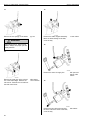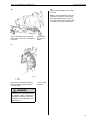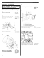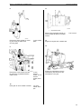
1
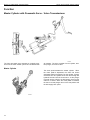
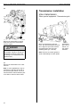
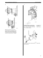
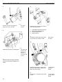
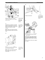
Service Manual
Trucks
Group
41
Hydraulically Actuated Clutch
(Including transmission removal)
VNL, VNM
PV776-TSP24581/1
Foreword
The descriptions and service procedures contained in this manual are based on design
and method studies up to October 1996.
The products are under continuous development. Vehicles and components produced
after the above date may therefore have different specifications and repair methods.
When this is believed to have a significant bearing on this manual, supplementary service
bulletins will be issued to cover the changes.
The new edition of this manual will update the changes.
In service procedures where the title incorporates an operation number, this is a
reference to an S.R.T. (Standard Repair Time).
Service procedures which do not include an operation number in the title are for general
information and no reference is made to an S.R.T.
The following levels of observations, cautions and warnings are used in this Service
Documentation:
Note: Indicates a procedure, practice, or condition that must be followed in order to
have the vehicle or component function in the manner intended.
Caution: Indicates an unsafe practice where damage to the product could occur.
Warning: Indicates an unsafe practice where personal injury or severe damage to the
product could occur.
Danger: Indicates an unsafe practice where serious personal injury or death could
occur.
Volvo GM Heavy Truck
Greensboro, NC USA
Order number: PV776-TSP24581/1
© 1996 Volvo GM Heavy Truck, Greensboro, NC USA
All rights reserved. No part of this publication may be reproduced, stored in
retrieval system, or transmitted in any forms by any means, electronic, mechanical, photocopying, recording or otherwise, without the prior written
permission of Volvo GM Heavy Truck.
Contents
General .................................................................................................... 3
About this Service Information ................................................................ 3
Specifications .........................................................................................
Clutch .....................................................................................................
Clutch Master Cylinder ..........................................................................
Transmission Slave Cylinder .................................................................
Hydraulic System ...................................................................................
Tightening Torques ................................................................................
5
5
5
6
7
7
Tools ....................................................................................................... 9
Special tools .......................................................................................... 9
Other equipment .................................................................................. 10
Design and Function ...........................................................................
Clutch and Hydraulic Clutch System .....................................................
Design ..................................................................................................
Function ...............................................................................................
11
11
11
14
Service Procedures .............................................................................
Clutch removal .....................................................................................
Clutch plate changing and installation ................................................
Flywheel pilot bearing replacing ..........................................................
Volvo clutch servo removal .................................................................
Volvo clutch servo installation .............................................................
Volvo clutch servo adjustment ............................................................
Master cylinder removal ......................................................................
Master cylinder installation ..................................................................
Clutch slave cylinder removal .............................................................
Clutch slave cylinder installation .........................................................
Clutch bleeding procedure ..................................................................
Upper clutch pedal adjustment ............................................................
Lower clutch pedal adjustment ............................................................
Micro-switch adjustment ......................................................................
Inhibitor valve splitter adjustment ........................................................
Transmission removal .........................................................................
Volvo transmission ............................................................................
Non-Volvo transmission ....................................................................
Transmission installation .....................................................................
Volvo transmission ............................................................................
Non-Volvo transmission ....................................................................
Shift linkage removal ...........................................................................
Shift linkage installation .......................................................................
19
19
20
22
23
24
24
25
27
31
31
33
34
34
35
36
38
38
42
44
44
48
50
51
1
2
Group 41 Hydraulically Actuated Clutch
About this Service Information
General
About this Service Information
The information and instructions contained in this Service Information pertain to the
following components:
Clutch
•
•
•
Volvo 17 single plate - model CL43S-O (previously KFD117E)
Volvo 15 double plate - model CL38D-O (previously KFD215B)
Spicer® Easy-PedalTM 1552 double plate, ceramic
Note: For more information on servicing the Volvo clutches, please refer to the Volvo
Service Manual 411–600, Clutch, Pull-Type — Volvo.
Clutch Master Cylinder
•
Hydraulic master cylinder with plastic reservoir.
Clutch Slave Cylinder
•
•
Volvo Transmissions-Volvo air assisted hydraulic servo
Other Transmissions-hydraulic slave cylinder
Note: For more clutch overhaul instructions, please refer to the Volvo Service Manual
411–600, Clutch, Pull-Type — Volvo.
3
4
Group 41 Hydraulically Actuated Clutch
Specifications
Specifications
Clutch
Volvo
Model
Size
mm (in.)
Max. Torque
Nm (lb•ft)
Spline Size
Facing Material
CL43S-O (single plate)
430 (17)
1850 (1365)
10-SAE
organic
CL38D-O (double plate)
380 (15)
1980 (1460)
10-SAE
organic
Size
mm (in.)
Max. Torque
Nm (lb•ft)
Spline Size
Facing Material
394 (15.5)
1730 (1275)
1970 (1450)
2240 (1650)
10-SAE
ceramic
Spicer
Model
Easy-Pedal® PlusTM 1552
(double plate)
Clutch Master Cylinder
P/N 1628218 (Volvo) or
8076243 (Non-Volvo) ............................................................................................................................. Non-serviceable
5
Group 41 Hydraulically Actuated Clutch
Specifications
Transmission Slave Cylinder
Note: Vehicles equipped with a Volvo transmission use a
pneumatic/hydraulic servo for clutch operation. Vehicles
equipped with a non—Volvo transmission use a hydraulic
slave cylinder.
Volvo Transmissions
Volvo Clutch Servo
Air assisted, hydraulic cylinder ................................................................................................................... P/N 1521371
Measurement
CL43S-O clutch
mm (in.)
CL38D-O clutch
mm (in.)
Basic setting (A) ...............................................................
55 ± 1.5 (2.16 ± 0.06)
55 ± 1.5 (2.16 ± 0.06)
Measurement (B) mm (in.) ...............................................
Max. 115 (4.53)
Max. 115 (4.53)
Stroke (C), mm (in.) .........................................................
27-29 (1.06-1.14)
27-29 (1.06-1.14)
Lever length (L), mm (in.) ................................................
150 (5.9)
130 (5.12)
Fuller or Rockwell Transmissions
Hydraulic Clutch Slave
Slave Cylinder, Hydraulic ........................................................................................................................... P/N 8075008
6
Group 41 Hydraulically Actuated Clutch
Specifications
Hydraulic System
Clutch Fluid ..................................................................................................................................... DOT 4 (SAE J1703)
Fluid Reservoir Capacity ................................................................................................................. 0.15 liter (0.16 qts.)
Total Hydraulic System Capacity ........................................................................................................ 0.3 liter (0.3 qts.)
Tightening Torques
Component
Nm
(ft•lbs)
CL430S-O ...............................................................................................................
37 ± 4
(27 ±3 )
CL380D-O ..............................................................................................................
65 ± 6
(48 ±4 )
Spicer® Easy-PedalTM 1552 ...................................................................................
60 ± 7
(45 ±5 )
26 ± 2
(19 ± 1)
Lock nut, push rod .................................................................................................
60 ± 10
(45 ± 7)
Air Connection ........................................................................................................
24 ± 2
(18 ± 1)
Fluid bleed nipple ...................................................................................................
10 ± 2
(7 ± 1)
Hydraulic connection ..............................................................................................
45 ± 5
(33 ± 4)
Mounting bolts ........................................................................................................
35
(26)
Hydraulic connection, line to fitting ........................................................................
40 ± 5
(30 ± 4)
Hydraulic connection, fitting to cylinder .................................................................
20
(15)
Mounting bolts ........................................................................................................
24 ± 4
(18 ± 3)
Hydraulic connection ..............................................................................................
40 ± 5
(30 ± 4)
Clutch Housing to Flywheel
Intermediate Ring - Volvo clutches
CL380D-O ..............................................................................................................
Clutch Servo - Volvo
Clutch Slave Cylinder - non Volvo
Clutch Master Cylinder
7
8
Group 41 Hydraulically Actuated Clutch
Tools
Tools
Special tools
The following special tools are required for work on the Volvo VN Series Hydraulic Clutch
System. The tools can be ordered from the Volvo GM Heavy Truck Corporation.
W4000833
999
999
999
999
6851
1821
6928
6902
Adjustment gauge
Slide puller
Bleeder
Centering drift
999 6857
999 6896
Lifting tool
Adapting fixture
(used with 6857)
9
Group 41 Hydraulically Actuated Clutch
Tools
Other equipment
The following items are considered common shop equipment and are necessary for the
repair procedures in this manual.
W4000817
Pinch pliers
Transmission jack
10
Pocket ruler
Feeler gauges
Group 41 Hydraulically Actuated Clutch
Clutch and Hydraulic Clutch System
Design and Function
Clutch and Hydraulic Clutch System
W4000835
Design
Volvo Clutches
The Volvo dry plate clutches are specifically matched to
engine and transmission combinations. Volvo uses two
types of dry plate clutches: single plate and double plate.
The double plate is mainly used for heavy duty transport
purposes.
The clutch movement (engagement, disengagement) is a
result of the servo rotating the cross shaft (fork assembly).
These clutches are called “pull-type” because the fork
assembly pulls the release bearing rearward to disengage
the clutch.
All of the clutches are of the diaphragm spring type
and are controlled by an air assisted hydraulic servo.
W4000822
W4000821
The single plate clutch consists of a
pressure plate, release bearing and
one clutch disc.
The double plate clutch consists of a
pressure plate, release bearing, intermediate pressure plate, straps, two
clutch discs and four centering lugs.
11
Group 41 Hydraulically Actuated Clutch
Clutch and Hydraulic Clutch System
Volvo Clutch Plate(s)
The Volvo clutch plates are dry with linings on both sides.
Each clutch plate consists of a disc, damper springs,
hub, and linings. The disc is connected to the hub by
friction elements and damper springs to provide a smooth
engagement and eliminate engine pulses.
The front plate hub is splined onto the transmission’s input
shaft. The rear plate is splined onto the outer diameter of
the front plate hub. The linings are organic, non-asbestos
material and are riveted to the disc.
W4000794
Flywheel plate
W4000795
Gearbox plate
Volvo Pressure Plate
The pressure plate is a powerful diaphragm spring. It is
mounted to the flywheel with six mounting bolts. When
the clutch pedal is depressed the spring force is removed
from the clutch plates and absorbed by the release
bearing. The clutch plates are then disengaged and stop
transmitting torque to the transmission.
W4000789
12
Group 41 Hydraulically Actuated Clutch
Clutch and Hydraulic Clutch System
Spicer Clutch
The Spicer Easy-Pedal® PlusTM 1552 double plate clutch
is a spring type clutch that is controlled by a hydraulic
slave cylinder. The clutch engagement/disengagement is
a result of the slave cylinder rotating the cross shaft and
fork assembly.
The Spicer double plate clutch consist of a pressure plate,
release bearing, intermediate plate, Positive Separator
PinTM, two clutch plates and a Kwik-adjustTM.
W4000831
Spicer Clutch Plates
The Spicer clutch uses ceramic linings on both clutch
plates. The plates are dampened with springs to reduce
torsional vibrations.
W4000832
Spicer Pressure Plate
The Spicer pressure plate is a spring type with 9 coil
springs.
W4000831
13
Group 41 Hydraulically Actuated Clutch
Clutch and Hydraulic Clutch System
Function
Master Cylinder with Pneumatic Servo - Volvo Transmissions
W4000835
The Volvo pneumatic servo operates on hydraulic pressure from the clutch master cylinder and is assisted with
air pressure. The servo consists of an air cylinder, reaction plunger, and control valve.
Master Cylinder
The clutch pedal activates the master cylinder. When
the clutch pedal is depressed, the clutch rod moves
downward pushing the plunger into the cylinder. Plunger
movement into the cylinder forces the fluid through the
hydraulic lines and into the clutch servo. As the plunger
is forced into the cylinder, the fluid supply duct from the
reservoir is closed. When the clutch pedal is released,
the clutch rod and plunger return to the rest position and
the fluid supply duct opens.
W4000840
14
Group 41 Hydraulically Actuated Clutch
Clutch and Hydraulic Clutch System
Pneumatic Servo
Clutch engagement
W4000857
When the clutch pedal is pressed, hydraulic pressure (10)
increases and the reaction piston (3) is pressed in the
direction of the arrow. This movement first shuts the
control valves upper seat (4b) and then the air outlet duct
(6).
As the reaction piston moves further, the rubber peg (4)
is pushed off its seat (4b) allowing pressurized air into the
air chamber (5). As a result of the increased air pressure,
the piston (7) moves in the direction of the arrow.
Fully depressed
W4000858
The reduction in hydraulic pressure allows the air pressure
to push back the control valve (4b) stopping the air supply.
Pressure is now stabilized, the reaction piston (3) and
rubber peg (4) are held in their positions until the position
of the clutch pedal is changed.
15
Group 41 Hydraulically Actuated Clutch
Clutch and Hydraulic Clutch System
Released
W4000859
When the clutch pedal is released, hydraulic pressure is
lowered and the pressure spring (11) presses back the
reaction piston. The rubber peg (4) closes the air supply
Servo Failure
If air pressure drops or the air system does not supply air
pressure, the servo will continue to function on hydraulic
pressure, however, this will require greater pedal effort.
WARNING
Increased pedal effort is required if servo air pressure
is lost. Increased pedal effort may make the vehicle
hard to control. Repair a damaged servo before driving
vehicle. Driving a vehicle without servo air pressure
could result in damage to the vehicle or personal injury.
16
and opens the air outlet duct (6). Air is now released from
the air chamber (5) and the piston (7) is returned to its rest
position by the force of the pressure plate spring.
Group 41 Hydraulically Actuated Clutch
Clutch and Hydraulic Clutch System
Master Cylinder with Slave Cylinder - Fuller or Rockwell Transmissions
W4000781
Master Cylinder
The clutch pedal activates the master cylinder. When
the clutch pedal is depressed, the clutch rod moves
downward pushing the plunger into the cylinder. Plunger
movement into the cylinder forces the fluid through the
hydraulic lines and into the clutch slave cylinder. As the
plunger is forced into the cylinder, the fluid supply duct
from the reservoir is closed. When the clutch pedal is
released, the clutch rod and plunger returns to the rest
position and the fluid supply duct opens.
W4000840
Slave Cylinder
The slave cylinder is connected to the master cylinder
through a steel braided hydraulic hose. The slave cylinder
operates on the hydraulic pressure from the master
cylinder. The adjustment indicator shows whether the
clutch is properly adjusted.
W4000816
17
18
Group 41 Hydraulically Actuated Clutch
Service Procedures
Service Procedures
3
Clutch removal
Volvo clutch
Transmission removed from vehicle
Other special equipment: 1821 Puller, 6857
Lifting tool, 6902 Centering drift
1
W4000790
T4006506
Install the centering drift 6902 into the
clutch.
Using a floor jack with tool 6857, place
the lifting hook of tool 6857 between
the pressure plate spring and housing.
Remove the clutch mounting bolts and
remove the clutch from the flywheel.
6857
4
Remove clutch from under the vehicle.
2
W4000789
Loosen the pressure plate mounting
bolts.
17 mm socket;
ratchet
19
Group 41 Hydraulically Actuated Clutch
Service Procedures
Clutch plate changing and installation
Volvo clutch
3
Inspect the clutch parts:
•
•
•
Pressure plate housing
Intermediate plate
Clutch plates
(engine side and gearbox side)
Release bearing
Clutch removed from vehicle (double plate
type clutch)
•
Part no.: 1161138 Heat resistant grease
Special tools: 6902 centering drift
Note: Refer to TSI Service Manual
411–600, Clutch, Pull-type — Volvo
for additional clutch overhaul information.
1
W4000791
Punch-mark the pressure plate housing and the intermediate plate for
proper alignment.
5
Remove the new engine side clutch
plate from the input shaft. Remove any
excess grease so it will not contaminate the clutch plates during operation.
2
W4000792
Remove the four hex head socket
screws that hold together the pressure
plate housing and intermediate plate.
Remove the pressure plate housing
and the gearbox side clutch plate.
20
4
Grease input shaft spline with heatresistant grease (p/n 1161138). Install
the new engine side clutch plate on
the input shaft. The side marked
“Flywheel-side non asbestos”
should be toward the flywheel. Pull
the clutch plate backwards and forwards on the shaft to properly spread
the grease.
6mm hex
socket; ratchet
6mm hex
socket;
ratchet; torque
wrench
Group 41 Hydraulically Actuated Clutch
Service Procedures
6
8
W4000792
Install the four hex head socket
screws and tighten them evenly.
9
W4000795
Place the gear box side clutch plate
on intermediate plate.
Note: The side marked “pressure
plate side” should be toward the
pressure plate housing (facing the
gearbox).
W4000796
Torque the hex screws to 26 ± 2 Nm
(19 ± 1 ft-lb).
7
10
T4006506
W4000791
Place the pressure plate on the intermediate plate and align the punch
marks.
6mm hex
socket
Using a floor jack with tool 6857, place
the lifting hook of tool 6857 between
the pressure plate spring and housing.
Install the centering drift 6902 through
the clutch and flywheel side clutch
disc.
Note: “Flywheel side” must be facing the flywheel.
21
Group 41 Hydraulically Actuated Clutch
Service Procedures
11
Flywheel pilot bearing replacing
VE D12 engine
Clutch removed
Special tools: 1821 puller, 2564 drift, 6956
cranking tool
1
W4000790
Install the clutch to the flywheel using
centering drift 6902. Hand tighten bolts
evenly to compress pressure plate.
Torque the nuts to 85 Nm (63 ft-lb).
18 mm socket;
torque
wrench; 6857;
6902
T2006733
Remove the flywheel pilot bearing with
tool 8121.
2
Clean the flywheel and check for damage.
3
T2006734
Set up a dial indicator probe on the flywheel so that the probe is against the
flywheel at a radius of 150 mm (5.9 in.)
from the center. Set the dial indicator
to zero (0). Rotate the flywheel with
tool 6956. Note the reading on the dial
indicator during flywheel rotation.
22
puller 1821
Group 41 Hydraulically Actuated Clutch
Service Procedures
4
If the dial indicator reading exceeded
0.20 mm (0.0079 in.), remove the flywheel and inspect and clean the
surface between the flywheel and the
crankshaft.
Volvo clutch servo removal
1
Note: If the flywheel is out of specification after cleaning the crankshaft
flange, the flywheel should be replaced. Refer to TSI Service Manual
210–600, Basic Engine, VE D12.
5
W4000867
Remove the air line to the servo cylinder. Remove the cotter pins from the
front and rear clevis pins and remove
both clevis pins. Lower the servo to
the floor.
pliers
2
T2006732
Install the new flywheel pilot bearing
using drift 2564.
2564
W4000867
Disconnect the vent line and the hydraulic line from the servo cylinder.
Note: A suitable drain pan will be
needed to catch leakage from the hydraulic line.
19 mm open
end wrench;
17 mm open
end wrench
23
Group 41 Hydraulically Actuated Clutch
Service Procedures
Volvo clutch servo installation
Volvo clutch servo adjustment
1
Position the servo cylinder into place
and hand tighten the hydraulic line.
1
Note: Install a new O-ring on the hydraulic line connection.
2
W4000824
Measure the distance “A” from the
clutch servo end to the lock nut. Adjust to 55 ± 1.5 mm (2.17 ± 0.05 in.).
15 mm
wrench; 19
mm wrench;
ruler
W4000867
Install the front and rear clevis pins
and secure with cotter pins.
3
Tighten the hydraulic line and connect
the air and vent lines. Torque the hydraulic connector to 45 Nm (33 ft-lb)
and the air line to 24 Nm (18 ft-lb).
pliers
19 mm open
end wrench;
17 mm open
end wrench;
17 mm crows
foot socket;
torque wrench
CAUTION
Improper clutch operation. If the
distance above is too long, the
clutch may not fully disengage. If
the distance is too short, the clutch
may not fully engage.
2
4
Bleed the air from the servo and
clutch system using the clutch bleeding procedure.
W4000824
Measure the distance “B” between
the clevis pin center and the end of
the clutch servo. If the distance exceeds 115 mm (4.5 in.) re-indexed the
clutch arm on the cross shaft to adjust.
Note: Only when the clutch arm has
been removed is this adjustment necessary.
24
ruler
Group 41 Hydraulically Actuated Clutch
Service Procedures
3
Master cylinder removal
1
W4000872
Pre-select splitter. Press the clutch
pedal until just before the splitter shifts
and measure from the upper edge of
the clutch pedal to the floor (E). Press
the clutch pedal until it strikes the
lower stop screw and re-measure from
the upper edge of the clutch pedal to
the floor. The pedal movement from
splitter to lower stop screw should be
40 ± 5 mm (1.5 ± 13/64 in.).
ruler
W4000855
Pull the floor mat back and remove
the plastic nuts fastening the left
panel. Remove the three torx screws
and the diagnostic connector. Pull the
heater hose out of cover and remove
the cover.
4
10 mm socket;
6” extension;
20 torx bit
2
W4000873
Measure the clutch servo stroke (D).
Stroke should be 27–29 mm
(1 9/16–1 9/64 in.).
ruler
W3000648
Remove the cover on the steering
wheel column by removing the ignition
key and the three torx screws.
20 torx bit; 3”
extension
25
Group 41 Hydraulically Actuated Clutch
Service Procedures
3
6
W3000654
Pull the dust covers back on the turn
signal and windshield wiper stalks.
4
Remove four torx screws from the
center dash cover. Pull the floor mat
back and remove the plastic nut.
5
W4000851
10 mm socket;
6” extension;
20 torx bit
Loosen and remove the fluid line from
the slave cylinder. Drain the brake
fluid into a drain pan or suitable container. Install the fluid line back onto
the slave cylinder to keep contaminants out of the system.
19 mm open
end wrench;
17 mm open
end wrench
7
W3000655
Remove the two clips at the bottom of
the steering column. Remove the
cover over the lower steering column
by removing the plastic rivets.
W4000819
Note: Be careful not to damage the
lower cover when removing.
Remove the clutch pedal return spring
to access the two master cylinder
mounting bolts.
Note: Depress the clutch pedal for
easier access to the mounting bolts.
26
13 mm deep
swivel;
ratchet; 6” extension
Group 41 Hydraulically Actuated Clutch
Service Procedures
8
Master cylinder installation
1
T4006731
W4000809
Remove the fluid line and remove the
master cylinder from the pedal plate
assembly.
17 mm open
end wrench;
12 mm open
end wrench
Note: Remove O-ring between the
master cylinder and the pedal plate
assembly.
CAUTION
Brake fluid can cause damage to
paint and painted surfaces.
9
Remove 45 degree angle fitting from
master cylinder.
Install reservoir on the master cylinder
and secure with band clamp. Torque
band clamp to 3 Nm (26 in-lb).
7mm socket;
ratchet
Note: Lubricate the mount tube on the
fluid reservoir (which connects to the
master cylinder’s rubber seal) before
the reservoir is fitted to the master
cylinder. Use grease p/n 8775046 or
8708640.
2
Clean the 45 degree angle fitting and
install it hand tight on the master cylinder. Use pipe sealant on the fitting.
12 mm open
end wrench
12 mm open
end wrench
10
T4006730
Remove the band clamp holding the
reservoir. Remove the reservoir by
pulling the reservoir out of the rubber
seal.
7mm socket
27
Group 41 Hydraulically Actuated Clutch
Service Procedures
3
5
W4000819
Install master cylinder. Make sure the
O-ring is fitted around the neck of the
master cylinder before the cylinder is
inserted into the pedal plate assembly.
Press the clutch pedal down to access
the two mounting bolts. Torque mounting bolts to 24 ± 4 Nm (18 ± 3 ft-lb).
13 mm deep
swivel; 6” extension;
torque wrench
W4000850
Tighten 45 degree fitting to proper angle and install the fluid line with a new
O-ring. Torque fluid line to 40 ± 5 Nm
(30 ± 4 ft-lb).
4
Install the clutch pedal return spring.
Note: Lubricate the spring end with
grease p/n 8708166.
12 mm open
end wrench;
17 mm open
end wrench;
17 mm crow
foot
6
W4000870
Remove the two slave cylinder mounting bolts and the clevis pin.
28
12 mm socket;
ratchet; pliers
Group 41 Hydraulically Actuated Clutch
Service Procedures
7
10
W4000810
Open the bleed screw and connect the
bleed tool. Clean the reservoir filler
cap area and remove the cap. Hold
the slave cylinder with the bleeder
screw at the lowest point and turn the
bleed pump on.
10 mm
wrench; bleed
tool 6928
W4000870
Install the clevis pin and the slave
cylinder mounting bolts with the operating range tag. Torque the mounting
bolts to 35 Nm (26 ft-lb).
12 mm socket;
pliers
11
Check for the correct operation of the
clutch. Re-check fluid level.
8
12
Install the lower steering column cover
with plastic rivets (pull floor mat back
to position the cover over the studs).
Note: Be careful not to damage the
cover when installing.
13
Install three torx screws and the plastic nut on the center of the lower dash
cover.
10 mm socket;
6” extension;
25 torx driver
W4000811
Stop bleeding when the fluid is at the
minimum level indicated on the side of
the reservoir. Close the bleeder screw.
Torque bleed screw to 10 Nm (7 ft-lb).
10 mm wrench
Note: Use clean DOT 4 fluid only.
9
Disconnect the bleeder tool and remove.
29
Group 41 Hydraulically Actuated Clutch
Service Procedures
14
16
W3000655
Install the two clips at the bottom of
the steering column cover.
17
W4000855
Install the left panel. Install the diagnostic connector. Install the heater
hose, three torx screws and the plastic
nut.
20 torx driver;
10 mm socket;
6” extension;
ratchet
15
W3000654
Put the dust covers in place on the
turn signal and windshield wiper
switches.
W3000648
Install the upper cover on the steering
column with three torx screws.
30
20 torx driver
Group 41 Hydraulically Actuated Clutch
Service Procedures
Clutch slave cylinder removal
1
Clutch slave cylinder installation
1
Install a new sealing washer on the
fluid hose fitting and install the fitting.
Torque the fitting to 20 Nm (15 ft-lb).
19 mm open
end wrench;
19 mm crow
foot
2
Mount the slave cylinder to the transmission temporarily with the two
mounting bolts.
3
W4000851
Remove the fluid hose from the slave
cylinder.
19 mm open
end wrench
Note: Use a catch pan to drain the
fluid.
2
W4000851
Install the fluid hose with a new
O-ring. Torque the hose to 40 ± 5 Nm
(30 ± 4 ft-lb).
19 mm open
end wrench;
17 mm open
end wrench;
17 mm crow
foot
4
Remove the slave cylinder for bleeding.
W4000870
Remove the slave cylinder mounting
bolts with the operating range indicator. Remove the clevis pin.
3
Remove the fluid hose fitting.
12 mm socket;
ratchet
19 mm wrench
31
Group 41 Hydraulically Actuated Clutch
Service Procedures
5
7
Disconnect the bleeder tool and remove.
8
Install clevis pin with new cotter pin.
9
W4000810
Plug power cord into cigarette lighter.
Place bleeder tool into brake fluid container. Open the bleed screw and
attach the bleeder hose to the bleeder
screw on the slave cylinder. Clean the
reservoir filler cap area and remove
the cap. Hold the slave cylinder with
the bleeder screw at the lowest point
and turn the bleed pump on.
Note: 24V motor working at half
speed.
6
W4000811
Stop the bleed when the fluid is at the
minimum level indicated on the side of
the reservoir. Close the bleeder
screw. Torque the bleeder screw to
10 Nm (7 ft-lb).
Note: Use DOT 4 fluid only.
32
6928
W4000870
Install slave cylinder with the two
mounting bolts. Be sure to install operating range indicator. Torque bolts
to 35 Nm (26 ft-lb).
10
Check for proper clutch operation. Recheck fluid level.
12 mm socket
Group 41 Hydraulically Actuated Clutch
Service Procedures
Clutch bleeding procedure
W4000836
1
Place the pick-up tube in a 4 liter (one
gallon) can of DOT 4 brake fluid.
6928
2
Plug the fluid pump wire into the dash
cigarette lighter receptacle.
Note: Watch the fluid level in the
reservoir to avoid it overspilling onto
the paint.
3
Connect the bleed hose to the slave
cylinder bleed nipple.
4
Loosen the bleed nipple about one
turn and use the metal “C” clamp to
lock the bleeder hose onto the nipple.
5
Remove the reservoir cap.
6
Using the ON/OFF switch on the wire,
turn ON the switch to start the pump.
When the fluid has reached the level
of the reservoir FULL mark, turn OFF
the pump.
11 mm wrench
7
Close the bleeder nipple. Remove the
clamp and hose. Torque the nipple to
10 ± 2.5 Nm (7 ± 1.8 ft-lb).
11 mm wrench
8
Check the clutch operation.
9
Check the fluid level and top off as
necessary. Replace the cap.
33
Group 41 Hydraulically Actuated Clutch
Service Procedures
Upper clutch pedal adjustment
Lower clutch pedal adjustment
1
1
W4000798
W4000799
Measure the play (3) in the clutch
pedal at the free position. Adjust the
upper screw (2) until 4–8 mm
(5/32–5/16 in.) play is obtained.
13 mm
wrench; 4 mm
Allen wrench
Note: Clutch pedal play is the clearance between the clutch rod and the
piston in the master cylinder. Clutch
adjustment does not affect pedal play.
2
Torque jam nut (1) to 24 Nm (18 ft-lb).
34
Insert the measuring instrument
through the opening in the panel for
the clutch pedal. Measure the amount
the adjusting screw extends from the
inside of the casting. Adjust the lower
screw (2) until it extends 19 mm
(3/4 in.) from the inside of the casting.
2
Torque jam nut (1) to 24 Nm.
13 mm deep
socket; 10”
extension;
torque wrench
13 mm
wrench; 4 mm
Allen wrench
13 mm deep
socket; 10”
extension;
torque wrench
Group 41 Hydraulically Actuated Clutch
Service Procedures
3
Micro-switch adjustment
1
W4000855
Install the left side clutch pedal panel.
25 torx bit
W4000855
Remove the left side clutch pedal
panel.
10 mm
wrench; torx
bit 25
2
W4000801
With the clutch pedal in the free position, place a 3 mm thick feeler gauge
on top of the L-bracket. Rotate the micro switch assembly down until the
switch bottoms out, then tighten the
mounting screw. Torque to 10 Nm
(7.5 ft-lb).
10 mm wrench
35
Group 41 Hydraulically Actuated Clutch
Service Procedures
2
Inhibitor valve splitter adjustment
1
W4000818
Note: The lower clutch pedal adjustment must be performed before the
inhibitor valve adjustment can be
made.
Loosen the pinch bolt and nut. Remove the inhibitor valve.
13 mm socket;
13 mm
wrench;
ratchet; 3” extension
W4000800
Note: This procedure requires two
technicians.
Fully depress the clutch pedal until it
contacts the stop (3) and hold it there.
3
Insert a ruler into the inhibitor valve
hole until it is against the clutch pedal
lever. Adjust the flat head adjusting
screw (1) to a distance of 53.5 mm
(2.10 in.) from the flat of the screw
head to the depressed clutch pedal
lever.
36
metric ruler;
#40 torx bit;
ratchet
Group 41 Hydraulically Actuated Clutch
Service Procedures
4
W4000818
Remove the ruler and slide the inhibitor valve into its bore. Slide the
valve in until it bottoms against the flat
head adjusting screw. Tighten pinch
bolt and nut to a torque of 24 Nm
(18 ft-lb).
13 mm socket;
13 mm
wrench;
torque
wrench; 3” extension
Note: Apply grease around the outside diameter of the valve before
installation.
37
Group 41 Hydraulically Actuated Clutch
Service Procedures
2
Transmission removal
Volvo transmission
Other special equipment: Transmission jack
1
W4000782
Disconnect the rear slip-yoke by disconnecting the U-joints (four bolts)
located behind the center bearing support.
W2002059
Risk of poisoning. Coolant is toxic. Do not drink
coolant. Use proper eye and hand protection when
handling. Keep coolant out of reach from children and
animals.
3
Disconnect the U-joint at the transmission yoke.
4
Remove center bearing support (two
bolts).
1/2”socket
1/2” socket
11/16” socket;
5/8” wrench
ratchet
5
WARNING
Risk of burns. Engine and fluids
may be hot. Never remove the
coolant drain plug or the expansion
tank cap when the engine is hot.
Allow the engine to cool before servicing.
Drain the coolant from the radiator.
The drain is located on the bottom of
the radiator.
38
W4000806
Remove fuel tank brace.
18 mm socket;
15 mm
wrench ratchet
Group 41 Hydraulically Actuated Clutch
Service Procedures
6
9
W4000807
Remove the engine cross member
from the top cover of the engine nodal
mounts.
18 mm socket/
wrench; 15
mm socket/
wrench
7
W4000860
Disconnect the wire harness from the
following sensors and cut the wire ties.
1
2
3
4
side cutters
Transmission temperature sensor
VSS (vehicle speed sensor)
Reverse lamps sensor
Range solenoid
10
W4000783
Remove the transmission oil filter
cover to access the coolant hoses. Cut
the hose clamp to remove the hoses.
8
Remove the coolant hose support
brackets.
14 mm socket;
side cutters
W4000861
Remove air lines (1 through 4) and “L”
brackets.
13 mm socket;
10 mm socket;
ratchet
3/8” open end
wrench; 5/8”
open end
wrench; 18
mm open end
wrench
39
Group 41 Hydraulically Actuated Clutch
Service Procedures
11
13
W4000846
Remove the two springs on the shifter.
W4000848
pry bar
WARNING
High spring tension. Risk of flying
debris. Always use proper eye and
hand protection.
Remove the shifter support assembly.
Move the shifter linkage to the side,
out of the way.
14 mm socket
14
12
W4000862
Remove the servo air supply line.
5/8” open end
wrench; side
cutters
W4000847
Remove the cotter key at the rod end
nut of the shift linkage. Remove the
rod end nut. Remove the rod end from
the side control lever.
side cutters;
19 mm wrench
15
W4000863
Remove the two clevis pins securing
the servo. Move the servo to the side,
out of the way.
40
side cutters
Group 41 Hydraulically Actuated Clutch
Service Procedures
16
18
Remove the transmission from under
the truck.
Note: In some applications it may be
necessary to raise the vehicle with a
floor jack and jack stands. This is for
the transmission and transmission jack
to be able to clear the vehicle frame.
W4000788
Place a transmission jack under the
transmission. Secure the transmission
to the jack.
transmission
jack; 18 mm
socket
17
W4000828
1
2
Nut
Stud
Remove the transmission mounting
bolts and remove the transmission
from the engine.
18 mm socket;
extension
WARNING
Transmission is top heavy and may
be unstable. Failure to remove the
transmission carefully could result
in damage to the transmission and
personal injury.
41
Group 41 Hydraulically Actuated Clutch
Service Procedures
Non-Volvo transmission
5
This procedure is meant to be a guide for removing
non-Volvo transmissions. Refer to the transmission
manufacturer’s literature for more information.
Remove the necessary air lines and
tie down clamps.
6 mm hex
socket; 12 mm
socket; side
cutters
Other special equipment: Transmission jack
1
Remove the battery cable.
2
Remove the drive shaft, center bearing and U-joint at the rear of the
transmission.
6
9/16” open
end wrench
1/2” 12 point
socket; 15 mm
socket; 18 mm
wrench
3
W4000812
1
2
3
4
temperature sender
reverse light sender
vehicle speed sensor (ECU)
vehicle speed sender (speedometer)
Remove the wires at the sensor connectors and tie down clamps.
W4000806
Remove the fuel tank brace.
side
cutters; 9/16” socket
7
15 mm socket;
18 mm wrench
4
W4000868
Remove the gear shifter lever by loosening the clamp bolt on the shift tower.
W4000802
Remove the oil cooler and the oil
cooler hoses at the transmission.
42
9/16” socket;
9/16” wrench;
5/8” wrench;
7/8” open end
wrench
11/16” socket;
5/8 wrench
Group 41 Hydraulically Actuated Clutch
Service Procedures
8
11
W4000869
1
temperature sender
Remove the temperature sender (1)
from the lower left side of the transmission.
5/16” wrench
W4000870
Remove the slave cylinder by removing the clevis pin and the two
mounting bolts.
12 mm socket;
pliers
12
Support the engine with a suitable tool.
13
9
W4000808
W4000807
Remove the cross member and the
top half of the engine/transmission
nodal mounts.
10
Drain gear oil into a suitable container.
15 mm
wrench/
socket; 18 mm
wrench/
socket; extension
Support the transmission with the
transmission jack and secure the
transmission to the jack.
1/2” drive
ratchet; drain
pan
43
Group 41 Hydraulically Actuated Clutch
Service Procedures
14
Transmission installation
Volvo transmission
Other special equipment: Transmission jack
1
W4000854
Remove the transmission mounting
bolts and remove the transmission
from the engine.
WARNING
Transmission is top heavy and may
be unstable. Failure to remove the
transmission carefully could result
in damage to the transmission and
personal injury.
15
Remove the transmission from under
the truck.
Note: In some applications it may be
necessary to raise the vehicle with a
floor jack and jack stands. This is for
the transmission and transmission jack
to be able to clear the vehicle frame.
44
W4000788
Move the transmission under the
truck. Jack the transmission into position to align the input shaft. Grease
input shaft spline with high heatresistant grease (p/n 1161138).
Note: Remove any excess grease to
avoid contaminating the clutch plates.
transmission
jack; 18 mm
wrench; 18
mm socket;
extension
Group 41 Hydraulically Actuated Clutch
2
Service Procedures
3
W4000828
1
2
mounting nut
stud
Install transmission mounting nuts
hand tight. Remove the transmission
jack. Torque transmission mounting
nuts to 92 Nm (68 ft-lb).
18 mm socket;
extension;
torque wrench
W4000864
Make sure the clutch fork is in the
proper position for installing the transmission. The fork and spring should
be behind the ears of the release bearing when the transmission is installed.
4
W4000863
Install the clutch servo clevis pins with
new cotter pins.
side cutters
45
Group 41 Hydraulically Actuated Clutch
Service Procedures
5
8
W4000862
W4000860
Connect the servo air supply line.
Torque to 24 Nm (18 ft-lb).
5/8” open
wrench
Install the wire harness and connect it
to the following sensors.
1
2
3
4
6
Transmission temperature sensor
VSS (vehicle speed sensor)
Reverse lamps sensor
Range solenoid
9
Tie wrap the wires and air lines making sure they are properly routed.
side cutters;
tie wraps
10
W4000861
Install the air lines to the transmission.
3/8” open end
wrench; 5/8”
open end
wrench; 18
mm open end
wrench
7
Install the shift and support assembly
using the shift linkage installation procedure.
W4000783
Install the transmission cooler hoses
with new hose clamps. Install the oil
filter cover (three bolts).
11
Connect all “L” brackets for the cooler
houses.
46
14 mm socket;
extension;
ratchet
14 mm socket;
10 mm socket;
ratchet
Group 41 Hydraulically Actuated Clutch
Service Procedures
12
15
W4000806
Install fuel tank brace.
15 mm socket;
18 mm socket;
ratchet; torque
wrench
W4000807
Install the engine cross member.
Torque mount bolts to 105 ± 20 Nm
(78 ± 15 ft-lb).
13
Connect the front section of the drive
shaft to the transmission yoke and install the center bearing. Torque center
bearing mount bolts to 105 Nm
(78 ft-lb).
15 mm socket/
wrench; 18
mm socket/
wrench; extension
16
1/2” 12 point
socket; 11/16”
socket; 5/8”
wrench
Note: Refer to the driveline manufacture for the proper torque of the U-joint
yoke.
14
W2002058
Fill cooling system with the proper
coolant mixture.
Note: Refer to TSI bulletin 260–600
(01) Coolant Requirements, Volvo
VE D12 for proper coolant concentration.
Note: Maximum fill rate of 2.5 gallons
per minute.
W4000782
Connect the slip yoke of the rear section to the front drive shaft.
Note: Refer to the driveline manufacturer for the proper torque of the
U-joint yoke.
1/2” 12 point
socket; torque
wrench
47
Group 41 Hydraulically Actuated Clutch
Service Procedures
Non-Volvo transmission
5
This procedure is meant to be a guide for installing
non-Volvo transmissions. Refer to the transmission
manufacturer’s literature for more information.
Other special equipment: Transmission jack
1
W4000854
W4000808
Set transmission on a transmission
jack. Secure the transmission to the
jack.
2
Roll the transmission under the truck
and jack up the transmission.
3
Install a new rubber bushing onto the
engine/transmission nodal mount pins.
Install the transmission mounting bolts
and torque them to 95–100 Nm
(70–75 ft-lb).
5/8” socket;
torque wrench
6
Remove transmission jack.
7
Remove engine support.
8
Note: Put anti-seize on the pin before
installing rubber bushing.
4
Push the transmission forward and
align the input shaft, making sure the
clutch fork is positioned properly over
the release bearing.
W4000807
Install engine mount (top half) and
cross member. Torque bolts to
105 ± 20 Nm (78 ± 15 ft-lb).
48
15 mm
wrench/
socket; 18 mm
wrench/
socket; torque
wrench
Group 41 Hydraulically Actuated Clutch
Service Procedures
9
12
W4000812
W4000871
Install gear lever and secure with the
clamp bolt. Torque bolt to 70 ± 15 Nm
(52 ± 11 ft-lb).
1
2
3
4
11/16” socket;
5/8” wrench
temperature sender
reverse light sender
vehicle speed sensor (ECU)
vehicle speed sender (speedometer)
Install temperature sender (1) and
torque to 48 Nm (35 ft-lb).
10
Install the air lines that were removed
during transmission removal.
9/16” socket
Note: Use pipe sealer on threads.
13
Connect the wire harness to the sensors and secure the wires with tie
wraps.
11
9/16” socket;
15/16” wrench
14
W4000870
Install clutch slave cylinder. Torque
the mounting bolts to 35 ± 6 Nm
(26 ± 6 ft-lb). Use a new cotter pin to
secure the clevis pin.
12 mm socket
W4000802
Install the transmission oil cooler and
hoses. Torque the 3/8” bolt to
48 Nm (35 ft-lb) and the 7/16” bolt to
70–85 Nm (50–65 ft-lb). Use pipe
sealer on oil cooler hoses.
9/16” socket/
wrench; 5/8”
wrench; 7/8”
wrench
49
Group 41 Hydraulically Actuated Clutch
Service Procedures
15
Shift linkage removal
1
Remove the upper shift lever boot
mounting bolts. Pull the upper and
lower shift lever boots up on the shift
lever so work be carried out through
the cab floor.
12 mm socket;
6” extension
2
W4000782
Install the drive shaft and center bearing. Center bearing to bracket; torque
to 105 Nm (78 ft-lb).
1/2” 12 pt.
socket; 15 mm
socket; 18 mm
wrench
Note: Refer to the driveline manufacturer for the proper torque values.
16
W4000849
Disconnect the air lines from the gear
lever knob and cut the plastic ties.
10 mm open
end wrench;
18 mm open
end wrench;
side cutters
3
W4000806
Install the fuel tank brace.
17
Fill the transmission with the manufacturers recommended oil. Torque drain
plug to 82–100 Nm (60–75 ft-lb).
15 mm socket;
18 mm wrench
9/16” wrench
18
Install the battery cable.
W4000847
19
Road test the vehicle to check for oil
leaks and air leaks.
Remove the cotter pin and nut from
the rod end assembly.
4
Remove the rod end assembly. Pull
down the rod end assembly until rod
end is out of control lever. Release
slowly to release spring tension. Disconnect both springs.
50
19 mm
wrench; side
cutters
hammer; ball
joint separator
Group 41 Hydraulically Actuated Clutch
5
Remove the nut from the control yoke
at support assembly. Lift assembly
out.
Service Procedures
19 mm socket
Shift linkage installation
1
6
W4000865
Remove the three mounting bolts for
the support assembly, then remove
the assembly.
14 mm socket
W4000848
Install the support assembly with three
mounting bolts. Torque the two upper
mounting bolts to 30 ± 5 Nm
(22 ± 4 ft-lb). Torque the lower mounting bolt to 48 ± 8 Nm (35 ± 6 ft-lb).
14 mm socket;
torque wrench
2
W4000866
Install the control assembly and nut.
Connect the springs to the rod assembly. Torque the control assembly nut
to 50 ± 10 Nm (37 ± 7 ft-lb).
19 mm
wrench; side
cutter; 19 mm
crow’s foot;
torque wrench
51
Group 41 Hydraulically Actuated Clutch
Service Procedures
3
W4000847
Position the rod end into the control
lever. Install the rod end nut and cotter pin. Torque the rod end nut to
40 ± 10 Nm (30 ± 7 ft-lb).
19 mm socket;
torque wrench
4
W4000849
Connect the air lines to the gear lever
knob. Tie wrap the air lines.
1 – Purple / Supply
3 – Yellow / Vent
21 – Black / Range cylinder
22– Blue / Splitter cylinder
5
Install the upper and lower shift boots
into the proper positions. Install four
mounting bolts.
6
Road test the vehicle to check for
proper shift operation and air leaks.
52
10 mm open
end wrench;
18 mm open
end wrench;
side cutters
12 mm socket;
6” extension;
torque wrench
53
Volvo GM Heavy Truck
Volvo GM Heavy Truck Corporation 7825 National Service Road P.O. Box 26115 Greensboro, NC 27402-6115
Volvo GM Canada Heavy Truck Corp. 6490 Vipond Drive Mississauga, Ontario L5T 1W8
PV776-TSP24581/1 (1500) 10.96