1
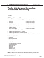
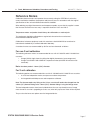
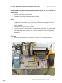
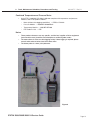
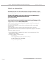
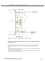
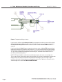
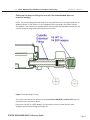
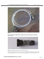
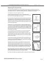
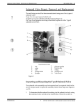
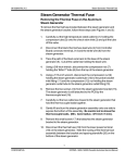
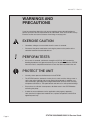
96-106775 Rev 5.0 WARNINGS AND PRECAUTIONS If you have questions about the unit you are repairing, please do not hesitate to contact your local SciCan representative for information. Also, the STATIM is heavy. Exercise caution and seek assistance when lifting or carrying units. EXERCISE CAUTION • Hazardous voltages are accessible when the cover is removed. • Disconnect the power cord before servicing the power mains portion of the controller board and associated devices. PERFORM TESTS • If the cover is removed, a dielectric strength test (Hi-Pot) AND a protective bonding impedance test (ground continuity) must be performed on the STATIM when the work is completed and after the cover has been returned to the unit. PROTECT THE UNIT Page 12 • Use only steam-process distilled water in the STATIM. • The STATIM contains electronic circuitry that is static sensitive. Always wear a static strap when working with or near printed wiring boards. In addition, use static footstraps, grounding mats and grounded work surfaces when servicing microprocessor devices. Transport boards and devices in static protected bags. • Ensure there is sufficient steam-process distilled water in the STATIM before activating the pump. • In order to ensure adherence to the applicable safety agency approvals, state, provincial, regional and national laws, replace components with SciCan approved parts only. 5000/5000S/5000 G4 Service Guide STATIM STATIM 2000/2000S Service Guide 2. Tools, Maintenance Schedules, Procedures and Testing 96-106775 Rev 5.0 Tools, Maintenance Schedules, Procedures and Testing Tools STATIM specific items from SciCan Before a STATIM can be serviced, the following special tools are required in addition to your service tool kit. These tools are available from SciCan or your nearest service depot: 1. 2. 3. 4. 5. 6. Control box Pump tester Water conductivity tester Solenoid plunger tube wrench 9/64” ball-end allen-key (hex) screwdriver Calibration cassette, SciCan 5000 Non S models only 7. Calibration cassette, SciCan 5000 All models SciCan Part # 01-103141S SciCan Part # 01-100713S SciCan Part # 01-103139S SciCan Part # 01-103471S SciCan Part # 01103469S SciCan Part # 01-103087S SciCan Part # 01-106366S Generic reference devices for calibration 8. Calibrated digital thermometer with ‘K’ type probe 9. Calibrated digital voltmeter with accuracy of 0.001 Volts 10. Calibrated digital pressure meter, 0 – 400 kPa absolute/0 – 7 bar absolute More details on recommended devices can be found in section ‘Recommended Reference Meters’ Electrical safety test devices 11. Hi-Pot tester 12. Ground continuity tester 13. Static strap 14. Static bags General tool list • • • • • • • • • • Phillips screwdriver Flat-blade electrician’s screwdriver Potentiometer trimmer Needle nose pliers Wire cutters Wrench 3/8” A/F Wrench 7/16” A/F Wrench 9/16” A/F Wrench 11/16” A/F Wrench 7/8” A/F Note: This tool list is a guide and suggests what is the minimum required to remove and replace components in the STATIM. Other tools may be required as an aid to servicing at the discretion of the individual service engineer. STATIM 2000/2000S STATIM 5000/5000S/5000 G4 ServiceService Guide Guide Page 13 2. Tools, Maintenance Schedules, Procedures and Testing 96-106775 Rev 5.0 Sample equipment set up for calibration of a non-S unit 1. Calibration cassette with detachable thermocouple 2. Digital voltmeter 3. Digital thermometer 4. (no pressure meter required) 5. Control box 6. 2x7 ribbon cable, LCD connector (connect to Controller Board header P3) 7. 1x7 cable, keypad connector (connect to Controller Board header P4) 8. 2x10 molded socket, test connector (connect to Controller Board header P1) 1 3 2 5 8 7 6 Figure 1 Sample equipment set up for calibration of S unit 1. Calibration cassette. 2. Digital voltmeter 3. Digital reference thermometer with thermocouple. (Fluke 51 with 80PK-26 probe shown) 4. Digital reference pressure meter (S only) (Druck DPI 750 R shown) 5. Control box 6. LCD connector cable (connect to Controller Board header P3) 7. Keypad connector cable (connect to Controller Board header P4) 8. Test connector cable (connect to Controller Board leader P1) 8 7 1 3 2 6 4 5 Figure 2 NOTE: The following section describes in greater detail the equipment depicted in Figures 1 and 2. Page 14 5000/5000S/5000 G4 Service Guide STATIM STATIM 2000/2000S Service Guide 2. Tools, Maintenance Schedules, Procedures and Testing The Control Box 96-106775 Rev 5.0 Figure 3 NOTE: Late model STATIMs with Rev.7 boards can be calibrated with the cover on using the unit’s software and keypad, making use of the Control Box as an option. For older models, use of a control box is required. The Control Box (5) is a service tool that allows a technician to operate the unit while it is being serviced. There are two kinds of Control Boxes you may encounter: one uses toggle switches, the other uses a membrane keypad arrangement similar to the keypad on the unit. When connecting the Control Box connectors to the Controller Board note the positions of Pin number 1 of the Control Box test connectors and Pin number 1 of the Controller Board headers. The Control Box has a display (LCD) and a variety of control switches that allow the technician to: 1. Operate the unit independently of the keypad mechanism, to manually activate the pump, valve or compressor, or run cycles. 2. Make frequently used Controller Board measurements by providing a common output and rotary switch for signal selection during calibration. See the Calibration Instructions in chapters 4 and 5 of this service manual. If only the display and button functions are being used, connect the LCD cable (6) to Controller Board connector P3, the keypad cable (7) to Controller Board connector P4 and power the STATIM ON. If the override or measurement functions are being used, connect the test connector cable (8) to connector P1 of the Controller Board in addition to the other cables. When using a toggle switch model of the Control Box, turn the switch to the ON position to activate the desired device. To turn the device OFF, turn the switch to the AUTO position. To select, start and / or stop a cycle, activate the appropriate push-button switch on top of the Control Box. Calibration uses the Select out +, Select out - jacks and a setting on the Rotary Switch to set the calibration operation desired for Revision 3.x/4.x Controller Boards (for STATIM 2000 units only). See Calibration Procedure 1 or chapter 4 of this service manual. When using a keypad model of the Control Box, the keypad switch must be held down to turn the desired device ON. Vref measurements use test leads, the Vref + and Vref - jacks and a voltmeter hooked up in series. Calibration uses the Select out + and Select out - jacks, test leads and a setting on the Rotary Switch to set the calibration operation desired for Rev. 3.x/4.x Controller Boards (for STATIM 2000 units only). The keypad of this Control Box provides the same features as a STATIM keypad. Note: The Control Box is for use with STATIM products ONLY. STATIM 2000/2000S STATIM 5000/5000S/5000 G4 ServiceService Guide Guide Page 15 2. Tools, Maintenance Schedules, Procedures and Testing 96-106775 Rev 5.0 Calibration Cassettes and Reference Meters Specially designed calibration cassettes allow technicians to take readings from within the cassette while the unit is in operation. In addition, calibration also requires the use of certain reference meters. Use the table below to identify the meters you will require. Sterilizer type Part Number Description Meter types required STATIM 2000 (non S)/ 2000 G4 01-103087S Calibration cassette STATIM 2000 Temperature only STATIM 5000 (non S)/ 5000 G4 01-103088S Calibration cassette STATIM 5000 Temperature only STATIM 2000S/ 2000S G4 01-103088S Calibration Cassette 2000S B Temperature and pressure STATIM 5000S/ 5000S G4 01-106367S Calibration Cassette 5000S C Temperature and pressure Calibration Cassettes The cassette of the STATIM unit is effectively a fixed volume chamber that contains instruments during sterilization. Saturated steam at a specific temperature and pressure is introduced to produce the correct conditions for sterilization. The cassette is part of a sealed system designed to contain Figure 4 the pressurized steam. To calibrate the unit’s temperature and pressure (if appropriate) monitoring devices, a special calibration cassette must be used. The calibration cassette allows a technician to independently monitor the temperature and pressure inside the cassette, ensuring the unit is operating in accordance to its original specifications and to national/international standards. The relevant cassette types are detailed in the chart above, and the following important information should be noted before choosing the appropriate cassette to use. Page 16 • Non S unit cassettes require a 1.6mm (1/16”) temperature probe and cannot be used with a 3.2mm (1/8”) temperature probe. (See meter details for probe diameter). • S unit cassettes have temperature fittings (one fitted and one in the cassette accessories supplied) that will allow the use of both 1.6mm (1/16”) and 3.2mm (1/8”) temperature probe. (See meter details for probe diameter). • S unit cassettes are designed for both temperature and pressure reference meters and are suitable for all models, S and Non S. If these cassettes are acquired, the non S, single port cassette is not required. • The non S unit cassettes should not be used to calibrate S class units. • Please note that when calibrating non-S units with an S unit cassette that the pressure meter will not be required and the test port will require the pressure tube supplied with the cassette to be connected to the pressure fitting to prevent steam leakage. 5000/5000S/5000 G4 Service Guide STATIM STATIM 2000/2000S Service Guide 2. Tools, Maintenance Schedules, Procedures and Testing 96-106775 Rev 5.0 Reference Meters Calibration reference meters are important for accurately setting the STATIM unit so that the correct sterilization conditions (temperature and pressure) occur in accordance with the original specifications of the unit and national/international standards. When ordering any digital thermometer and temperature probe, ensure that the supplier is aware that the area where the most accuracy is required is between 130°C and 140°C. Temperature meters and probes should always be calibrated as a matched pair. Test equipment should be calibrated on a regular basis based on the manufacturer’s recommended calibration interval. Calibration of reference equipment used with autoclaves should ALWAYS be to national or international standards by a certified calibration laboratory. A number of meters are recommended by SciCan and are referenced as follows: For non-S unit calibration The following reference meters are recommended for use with 01-103087S and 01-103088S test cassettes: • • Omega HH81A single channel multifunction digital thermometer (www.omega.com) Omega TJ36-CASS-116G-6-SMP-M Temperature Probe (with SMP-M miniature male connector). Note: the above probe is 1.6mm (1/16”) diameter. For S unit calibration The following options are recommended for use with 01-106366S and 01-106367S test cassettes: • A set of two independent meters, one pressure and one temperature. • An integrated hand-held pressure and temperature calibrator. Note: The thermocouple entry fitting on the S class cassette will need to be changed from the 3.2mm (1/8”) diameter fitting to the 1.6mm (1/16”) diameter fitting if using the Omega meter. The two independent meters have been included where the user may already have an Omega meter for non-S use who is upgrading to S class use, when only a pressure meter will be required. They are also the lower cost options over the integrated device. STATIM 2000/2000S STATIM 5000/5000S/5000 G4 ServiceService Guide Guide Page 17 2. Tools, Maintenance Schedules, Procedures and Testing 96-106775 Rev 5.0 Recommended separate temperature and pressure meters for S unit calibration temperature • Fluke 51 Series II Digital Thermometer. • Fluke 80PK-26 SureGrip Tapered Temperature Probe. Notes: • The flexible thermocouple included with the Fluke digital thermometer will not be used for calibrating SciCan sterilizers. If you wish to use the flexible thermocouple in the future, SciCan advises you to consult the digital thermometer’s manual for setting a temporary offset, if required. • The above probe is 3.2mm (1/8”) diameter. • Technicians already in possession of the Omega HH81A or equivalent, and the associated probe can use this meter as a replacement for the Fluke 51 and 80PK-26 probe. Note that the probes are of different diameter and a cassette compression fitting change may be appropriate. Pressure • Druck DPI 705R Absolute Pressure Meter with external 0 - 7 bar absolute pressure transducer with ¼” NPT female thread. Figure 5 Page 18 5000/5000S/5000 G4 Service Guide STATIM STATIM 2000/2000S Service Guide 2. Tools, Maintenance Schedules, Procedures and Testing 96-106775 Rev 5.0 Combined Temperature and Pressure Meter • Heise PTE-1 Handheld LCD digital calibrator complete with temperature and pressure modules, and PT100 probe as follows: Meter (without data logging capabilities) — PTEC = X X 4 4A Pressure Module — HQS2 B A A 400 kPa A Temperature Module — HQS RT1 PT-100 RTD Probe Pt-100 — PT5 Notes: • These product references are very specific, and the local supplier of Heise equipment (see www.heise.com) should be consulted prior to confirming order codes. • The meter above is of the non data logging variety. If data logging is required, please consult order code variations from Heise data sheet. • The above probe is 3.2mm (1/8in) diameter. Figure 6 STATIM 2000/2000S STATIM 5000/5000S/5000 G4 ServiceService Guide Guide Page 19 2. Tools, Maintenance Schedules, Procedures and Testing 96-106775 Rev 5.0 Setting Up your Reference Meters With certain meter types, some sub-assembly procedures will need to be undertaken to connect the device to your Statim calibration cassette. All cassettes are supplied with the necessary accessories to enable you to convert your meter of choice from those recommended above, to the appropriate fitting on the cassette. 01-103087S and 01-103088S cassettes (non S calibration) with Omega HH81A reference meter and TJ36-CASS-116G-6-SMP-M Temperature Probe. No sub-assembly required. To insert the temperature probe (thermocouple) into the compression fittings, loosen the clamp nut attached to the cassette extension fitting and insert the probe into the fitting as far as it will go. A slight resistance will be felt as the probe passes through the seal. Tighten the clamp nut until a steam/air tight seal is achieved. DO NOT OVERTIGHTEN. NOTE: The non S calibration cassette fitting is NOT compatible with the Fluke and Heise 1/8” (3.175mm) temperature probes. 01-106366S and 01-106367S cassettes (S-class calibration) with ALL recommended reference meters S-class calibration cassette kits contain a number of accessories for use with various recommended reference meters and will need to be set up to suit the appropriate meters before use. Contents of calibration cassette kit: • Cassette (2000S or 5000S as appropriate) with ‘generic’ pressure and temperature fittings attached (see Figure 7 below) • Accessories as follows: (inside the cassette) Page 20 1 x Pressure tube 2 x Male Swagelok B-QC4-S-2PM ‘Quick Connect’ fittings. 1 x 1/8 NPT female to ¼ NPT male adaptor 1 x 1/8” (3.175mm) probe fitting. 5000/5000S/5000 G4 Service Guide STATIM STATIM 2000/2000S Service Guide 2. Tools, Maintenance Schedules, Procedures and Testing 96-106775 Rev 5.0 Figure 7. S-class ‘generic’ fitting configuration (2000S cassette shown) Setting up the temperature fittings for use with the recommended temperature reference meter(s) The temperature fitting (right hand fitting when facing the front of the cassette) is fitted with a compression fitting that consists of a body, clamp nut and conical compression washer. (See Figure 8) There are two fittings supplied with the cassette, one for a 1/8” (3.175mm) temperature probe and one for a 1/16” (1.6mm) temperature probe. NOTE: The 1/16” fitting is attached to the cassette when supplied and the 1/8” fitting is in the pack of accessories supplied with the cassette. STATIM 2000/2000S STATIM 5000/5000S/5000 G4 ServiceService Guide Guide Page 21 2. Tools, Maintenance Schedules, Procedures and Testing 96-106775 Rev 5.0 Figure 8. Temperature fitting cut-away If you have the SciCan supplied Omega HH81A type temperature reference meter with the 1/16” (1.6mm) temperature probe (normally used with the Non S-class type calibration cassette) then the compression fitting attached to the S class cassette is correct and does NOT have to be removed. If you have either the Fluke 51 type temperature reference meter, or Heise PTE1 type combined temperature and pressure reference meter then the 1/16” (1.6mm) compression fitting (complete) will need to be removed from the extension piece attached to the cassette and replaced with the 1/8” (3.175mm) compression fitting from the accessory kit, as both of these meters have 1/8” (3.175mm) thermocouple probes. NOTE: PTFE tape should be used when assembling these parts to ensure a steam tight seal. To insert the relevant temperature probe (thermocouple) into either of the appropriate compression fittings, loosen the clamp nut and insert the probe into the fitting as far as it will go. A slight resistance will be felt as the probe passes through the conical seal. Tighten the clamp nut until a steam/air tight seal is achieved. DO NOT OVERTIGHTEN. Page 22 5000/5000S/5000 G4 Service Guide STATIM STATIM 2000/2000S Service Guide 2. Tools, Maintenance Schedules, Procedures and Testing 96-106775 Rev 5.0 Setting up the pressure fittings for use with the recommended pressure reference meter(s) NOTE: The pressure fitting (left hand fitting when facing the front of the cassette) is fitted with an adaptor to attach ¼” BSP devices such as hypodermic pressure fittings. (See Figure 9 below). This adaptor is not used with the standard SciCan pressure tube and should be removed from the cassette extension fitting before attaching the pressure tube. Figure 9. Pressure fitting cut-away To set up the cassette for use with the recommended Druck DPI705R and Heise PTE1 pressure reference meters, proceed as follows: Remove the 1/8 NPT to ¼ BSP adaptor. (The accessories for the cassette include 2 male Swagelok ‘Quick connect’ fittings (see Figure 10). STATIM 2000/2000S STATIM 5000/5000S/5000 G4 ServiceService Guide Guide Page 23 2. Tools, Maintenance Schedules, Procedures and Testing 96-106775 Rev 5.0 Figure 10. Male Swagelok B-QC4-S-2PM ‘Quick Connect’ fitting. Attach and tighten the ‘Quick Connect’ fitting to the cassette extension fitting in place of the 1/8 NPT to ¼ BSP adaptor (see Figure 11). NOTE: PTFE tape should be used when assembling these parts to ensure a steam tight seal. Figure 11. Male Swagelok ‘Quick Connect’ fitting and cassette extension fitting assembly. Attaching the pressure tube to the cassette The pressure tube (see Figure 12) supplied with the calibration cassette is designed to insulate the pressure transducer used with the pressure reference meter from the high temperatures experienced during sterilization, which may damage the transducer. Page 24 5000/5000S/5000 G4 Service Guide STATIM STATIM 2000/2000S Service Guide 2. Tools, Maintenance Schedules, Procedures and Testing 96-106775 Rev 5.0 Figure 12 The tube is fitted with a Swagelock, self sealing ‘Quick Connect’ QC4 female connector (see Figure 13) on either end. These connectors attach to the male ‘Quick Connect’ fitting shown in Figure 10 above. Figure 13. Swagelock ‘Quick Connect’ QC4 female connector To attach the pressure tube to the cassette (via the male Swagelok connector), press the male and female fitting together until a ‘click’ is heard and the couplings are firmly attached. (See Figure 14) STATIM 2000/2000S STATIM 5000/5000S/5000 G4 ServiceService Guide Guide Page 25 2. Tools, Maintenance Schedules, Procedures and Testing 96-106775 Rev 5.0 Figure 14. Assembled male fitting, female fitting and cassette extension fitting Attaching the pressure tube to the recommended pressure reference meter (s) Important notes: • Attaching the pressure tube to the reference meter is achieved using the second male Swagelok b-qc4-s-2pm fitting supplied with the cassette. • Attaching the tube to the connector is as described in the section above, however, the second male fitting will need to be installed onto the pressure reference meter prior to attempting this. • How the second male fitting is attached will depend on the type of reference meter used. Assembling the Swagelok b-qc4-s-2pm ‘quick connect’ fitting to the Druck dpi 705r absolute pressure meter external 0 - 7 bar absolute pressure transducer with ¼” NPT female thread. NOTE: To complete this assembly you will need to locate the 1/8 NPT female to ¼ NPT male adapter supplied with the S-class calibration cassette. (See Figure 15 for assembly) . Page 26 5000/5000S/5000 G4 Service Guide STATIM STATIM 2000/2000S Service Guide 2. Tools, Maintenance Schedules, Procedures and Testing 96-106775 Rev 5.0 Figure 15. Pressure transducer with adapter and Swagelok connector attached. Install Swagelok connector (1) onto adaptor fitting (2) DO NOT OVERTIGHTEN FITTING. NOTE: The use of P.T.F.E. tape as shown is essential to ensure the connection is free from steam leaks. If the joint leaks, steam can enter the transducer and damage the unit internally. Install assembly (from previous step) onto external pressure sensor (3) supplied with the Druck DPI 705R. DO NOT OVERTIGHTEN FITTING. NOTE: The use of P.T.F.E. tape as shown is essential to ensure the connection is free from steam leaks. If the joint leaks, steam can enter the transducer and damage the unit internally. The pressure tube can now be attached to the pressure transducer. STATIM 2000/2000S STATIM 5000/5000S/5000 G4 ServiceService Guide Guide Page 27 2. Tools, Maintenance Schedules, Procedures and Testing 96-106775 Rev 5.0 Figure 16, below, shows the meter, pressure transducer and pressure tube attached to a calibration cassette. Figure 16 Page 28 5000/5000S/5000 G4 Service Guide STATIM STATIM 2000/2000S Service Guide 2. Tools, Maintenance Schedules, Procedures and Testing 96-106775 Rev 5.0 Assembling the Swagelok B-QC4-S-2PM ‘Quick Connect’ fitting to the internal pressure module supplied with the Heise hand held calibrator. NOTE: You do NOT need the 1/8 NPT female to ¼ NPT male adaptor for this device. (see Figure 17 for assembly). Figure 17. Heise meter with Swagelok fitting attached to pressure module. Insert and tighten the Swagelok fitting into the 1/8 NPT female thread of the pressure module. DO NOT OVERTIGHTEN FITTING. NOTE: The use of P.T.F.E. tape as shown is essential to ensure the connection is free from steam leaks. If the joint leaks, steam can enter the module and damage the unit internally. The pressure tube can now be attached to the pressure module. STATIM 2000/2000S STATIM 5000/5000S/5000 G4 ServiceService Guide Guide Page 29 2. Tools, Maintenance Schedules, Procedures and Testing 96-106775 Rev 5.0 Figure 18, below, shows the meter with temperature probe and pressure tube ready to attach to a calibration cassette. Figure 18. Heise hand held calibrator with temperature module, pressure module, PT 100 temperature probe and pressure tube. Page 30 5000/5000S/5000 G4 Service Guide STATIM STATIM 2000/2000S Service Guide 2. Tools, Maintenance Schedules, Procedures and Testing 96-106775 Rev 5.0 Annual Service Requirements Important notes: • • • • The following schedule is designed as a guide for SciCan approved trained service engineers and applies to all STATIM 2000/5000/G4 models. The operations contained in this guide are for use during standard service intervals on functioning machines. Any operations or components required over and above this guide will be at the discretion of the service engineer and the customer and additional to the requirements outlined below. Components other than the routine annual service components may require changing due to wear and tear or failure but only require changing as and when degradation or failure occurs and should not need to be changed routinely on an annual basis. These may be identified during service and changed as appropriate. Consumable items such as seals and filters may require changing at more frequent intervals outside of normal service intervals dependent on the frequency of use of the unit. Service Schedule Standard service parts required for STATIM 2000/2000S and G4 variants: Part Number Description 01-100028S Seal and Lubricant kit A/B 01-100207S Filter for air compressor, STATIM 2000/2000S (where fitted) 01-102119S Filter Biological, B/C (where fitted) 01-100574S Check valve, B 01-100998S Repair, Solenoid valve (Honeywell) A/B/C/D Standard service parts required for STATIM 5000/5000S and G4 variants: Part Number Description 01-101649S Seal and Lubricant kit C 01-101652S Filter for air compressor, STATIM 5000/5000S (where fitted) 01-102119S Filter Biological, B/C (where fitted) 01-101627S Check valve, C 01-100998S Repair, Solenoid valve (Honeywell) A/B/C/D STATIM 2000/2000S STATIM 5000/5000S/5000 G4 ServiceService Guide Guide Page 31 2. Tools, Maintenance Schedules, Procedures and Testing 96-106775 Rev 5.0 Service Procedures Main unit With cover on Run cycle on unit to check for leakage or faulting. Check unit’s overall condition, including exhaust tube and bottle. Clean bottle, tighten fittings and check for kinks in exhaust tube as appropriate. With cover off Check internal condition of unit, pay particular attention to corrosion. Check water reservoir for contamination. If necessary, disconnect and remove reservoir, clean and rinse with warm distilled water. Do not use any chemicals. Refit reservoir. Check and clean probes if required. Remove and fit new bacteriological filter. (where fitted) Remove and fit new compressor filter. (where fitted) Remove and fit new solenoid plunger and associated parts. Remove and fit new check valve. Cassette Remove cassette seal. Clean process residue from all surfaces of cassette. (Use chlorine-free soap and scrub with cleaning pad designed for Teflon.) Check cassette for corrosion under seal seat. Check cassette for damage. Note: pay particular attention to the rear hinge and rear wall of the base as damage in this area may cause steam leakage even if a new seal is fitted. Fit new cassette seal. Diagnostics and Testing Note: •C ontrol box, appropriate test cassette (with temperature and pressure port for ‘S’ units and temperature port only for non ‘S’ units), appropriate reference meters (temperature and pressure for ‘S’ units and temperature only for non ’S’ units) and voltage meter are required for this section. •F or correct diagnostics and calibration of ‘S’ units, both temperature AND pressure meters MUST be used. Check running function of pump, solenoid valve and compressor (control box buttons). Cassette must be disconnected from probes. Check pump flow in accordance with steam generator type and correct as required. Check reference voltage as appropriate to board type and adjust as required. Not required on revision 7 units. Switch off machine and switch on in calibration mode as appropriate to model. Check steam generator thermocouple calibration as appropriate to board type. Note: steam generator calibration is not required for software revision numbers XXXXR4XX onwards. During the above cycle, check pipe work and fittings for steam leaks. Page 32 5000/5000S/5000 G4 Service Guide STATIM STATIM 2000/2000S Service Guide 2. Tools, Maintenance Schedules, Procedures and Testing 96-106775 Rev 5.0 Check and adjust chamber thermocouple calibration as appropriate to board type. Note: on ‘S’ class units, pressure transducer calibration using the pressure reference meter must be done during this phase. Software revision XXXXR4XX onwards requires this to be done at barometric pressure at the start of the cycle. Previous software variants require this to be done during the sterilization phase. When set, and during the running cycle, check that the chamber temperature matches the reference meter and that actual and theoretical pressure are within 1 kPa. This is important for the efficient balance of the control and validation circuits. Failure to achieve this may result in unnecessary cycle failures. Re-check steam generator thermocouple calibration as appropriate to board type. • Note 1: steam generator calibration is not required for software revision numbers XXXXR4XX onwards. • Note 2: if the initial steam generator calibration offset and final steam generator caibration offset are > 8 hexadecimal values apart, the steam generator MAY be compromised and further investigation should be undertaken. After completion of calibration, run a standard cycle to check temperature and pressure values. Reinstall cover, and check all cycles are available. Insert customer’s cassette and run standard cycle. Check for leaks. For revision 7 units ONLY: Enter service mode and activate ‘Back up NVRAM’. STATIM 2000/2000S STATIM 5000/5000S/5000 G4 ServiceService Guide Guide Page 33 2. Tools, Maintenance Schedules, Procedures and Testing 96-106775 Rev 5.0 Routine Maintenance Schedule and Procedures To maintain the STATIM in good order between annual services, follow these guidelines: Daily Water Reservoir • Replace water as needed. • For opthalmic use, drain at the end of every workday, leave empty, and refill at the start of the next workday. Water Bottle • Empty the waste bottle every time you refill the reservoir. • Fill with water, up to MIN line marking. You may also add some chlorine-free disinfectant. Weekly Cassette • Wash the interior of the cassette with dishwashing soap or a mild detergent that does not contain chlorine. • Scrub the inside with a cleaning pad designed for use with Teflon™-coated surfaces. • After removing all traces of the detergent, treat interior surfaces of the cassette with the STAT-DRI™ Plus drying agent to enhance the drying process. Order more STAT-DRI™ Plus from SciCan quoting 2OZPLUS, 8OZPLUST, or 32OZPLUS. Please note that STAT-DRI drying agent is not be to used with the U.S. G4 models (G4-121101 and G4-201103). Biological and/or Air Filter • Check the filter for dirt and moisture. Replace if dirty. Call for service if wet. Water Reservoir Filter • Check the water reservoir filter every week and clean if necessary. Replace only if necessary. Every 6 months Cassette Seal • Replace every 500 cycles or six months (whichever is first), or whenever necessary. Biological and/or Air Filter • Page 34 Replace every 500 cycles or six months (whichever is first). 5000/5000S/5000 G4 Service Guide STATIM STATIM 2000/2000S Service Guide 2. Tools, Maintenance Schedules, Procedures and Testing 4 Draining the Reservoir 96-106775 Rev 5.0 1 If you have to service the reservoir, ship the STATIM, or move the unit more than a short distance, the reservoir will need to be drained to prevent potential water damage to the internal components (particularly the electronic and electrical components) of the unit. Also, in some regions of the world, local or national guidelines recommend routine draining and cleaning of the reservoir to reduce the potential of the accumulation of contaminants in the feed water. 2 Figure 19 3 To drain the water from the reservoir, carefully move the STATIM to the edge of the work surface and proceed as follows (see Figure 19): • The front leveler feet (1) should be approximately 12 mm (1/2 inch) from the edge so the unit remains securely seated on the work surface. • Lift the front left corner of the STATIM upward and remove the drain tube (2) from the clip (3) located on the underside of the unit. Gently pull the tube out as far as possible so the free end can be positioned over a container when the unit is lowered back to the work surface. • Remove the stopper (4) from the end of the drain tube and allow the water to drain from the reservoir. • When water no longer drips from the drain tube, replace the stopper. • Lift the front left corner of the STATIM upward and re-insert the tube into the clip on the underside of the unit. Push the excess length of tubing back into the unit. Cleaning the Cassette Keeping the STATIM cassette clean is good clinical practice and assists in the proper functioning of the unit. SciCan recommends that the interior surface be cleaned at least once a week. Cleaning the inside of your cassette is very important if you regularly sterilize lubricated instruments. Use dish washing soap or a mild detergent that does not contain chlorine. Scrub the inside of the cassette with a cleaning pad designed for use with Teflon™ coated surfaces. After scouring, rinse thoroughly with water to remove all traces of the detergent. Figure 20 Coating the entire inside surface with STAT-DRI drying agent induces water to form an even coat on the inside surface, without beading. The water in contact with the hot cassette surfaces also evaporates much more efficiently. Spotting is minimized and instruments dry much better. STATIM 2000/2000S STATIM 5000/5000S/5000 G4 ServiceService Guide Guide Page 35 2. Tools, Maintenance Schedules, Procedures and Testing 96-106775 Rev 5.0 STAT-DRI should be applied every 10 cycles, and after every cassette cleaning. STAT-DRI is available from your SciCan Dealer. Please note that STAT-DRI drying agent is not be to used with the U.S. G4 models (G4-121101 and G4-201103). Cleaning the Water Reservoir Filter (where fitted) This water reservoir filter should be cleaned at least once a week or when required. The filter can easily be removed and cleaned by placing the filter upside down under running water to wash away the particles until clean, and then placed back into the reservoir opening. Replacement water reservoir filters are available from you SciCan dealer. Figure 21 Cleaning the Water Reservoir Check the reservoir for dirt or particles. The reservoir may be cleaned by draining followed by cleaning and rinsing with steam process distilled water ONLY. Use of chemicals or cleaning agents is not recommended and could cause damage to the unit. Changing the air filter and bacteria retentive filter (where fitted) Never re-use an old filter. Never run the unit without a clean filter in place. After each sterilization cycle, the compressor forces air through the cassette to rid it of steam and to dry the instruments. The air is drawn into the compressor through one or two filters located at the back of the unit, depending upon which unit is being serviced. Note: that some units may not have both or either filters fitted depending on age, unit type, compressor type, or if a compressor is fitted. Filters on the STATIM 2000/2000S/2000 G4 The STATIM 2000 type units draw air into the compressor (where fitted) through a circular foam air filter located behind a cover plate on the rear of the compressor. This plate can be accessed from the rear of the unit with the cover still attached. The air is then directed to the steam generator and cassette, by the compressor, through a bacteria-retentive air filter (where fitted) which is held in a bracket attached to the rear cover of the unit. If both filters are present, always change both filters at the same time. Page 36 5000/5000S/5000 G4 Service Guide STATIM STATIM 2000/2000S Service Guide 2. Tools, Maintenance Schedules, Procedures and Testing 96-106775 Rev 5.0 To change the filters, proceed as follows (see Figure 22): Bacteria Retentive Filter 2 1. Disconnect the inlet tube (1) from the bacteriaretentive filter (3) and remove the filter from the filter bracket (4). Note the orientation of the Arrow mark on the filter and bracket. 3 4 1 2. When the filter is free of the bracket, carefully disconnect the outlet tube (2) from the filter. Do not pull on this tube. 3. Before installing the replacement bacteria-retentive filter check that the arrow mark on the filter matches the direction of the arrow on the bracket. Push the left hand filter fitting into the outlet tube. 4. Gently press the replacement filter into the filter bracket. The arrow mark on the filter is facing out and pointing to the left. 5. Re-connect the inlet tube to the right-hand filter fitting. Compressor Filter 1. Remove the screw (5) holding the compressor plate (6) to the back of the compressor (7).Remove the plate. 2. Remove and discard the old filter. 3. Install the new filter (8), and secure the compressor plate to the rear of the compressor using the screw retained from disassembly. 7 8 6 5 Figure 22 Filters on the STATIM 5000/5000S/5000 G4 The STATIM 5000 type unit draws air into the compressor via a tube connected to a cylindrical air filter located on the chassis behind bacteria retentive filter bracket. Note: On certain 5000 models (dependent on compressor type) this filter may not be fitted. The air is then directed to the steam generator and cassette, by the compressor, through a bacteria-retentive air filter which is held in a bracket attached to the rear cover of the unit. If both filters are present, always change both filters 4 at the same time (see diagram below). To change the filters (where fitted), proceed as follows (see diagram above): Bacteria-Retentive Filter 1. Disconnect the inlet tube (1) from the bacteria-retentive filter (3) and remove the filter from the filter bracket (4). Note the orientation of the arrow mark on the filter and bracket. 2. When the filter is free of the bracket, carefully disconnect the outlet tube (2) STATIM 2000/2000S STATIM 5000/5000S/5000 G4 ServiceService Guide 2 Guide Figure 23 3 1 from the filter. Do not pull on this Page 37 2. Tools, Maintenance Schedules, Procedures and Testing 96-106775 Rev 5.0 tube. 3. Before installing the replacement bacteria-retentive filter check that the arrow mark on the filter matches the direction of the arrow on the bracket. Push the left hand filter fitting into the outlet tube. 4. Gently press the replacement filter into the filter bracket. The arrow mark on the filter is facing out and pointing to the left. 5. Re-connect the inlet tube to the right hand filter fitting. Compressor Filter 1. To enable access to the compressor filter, disconnect the inlet tube (4) from the bacteriaretentive filter (2) and remove the filter from the filter bracket (3). Note the orientation of the arrow mark on the filter and bracket. 2. When the filter is free of the bracket, locate and remove compressor filter (5) by unscrewing anti-clockwise using thumb and forefinger. Note: the filter should only be finger tight. 3. Install new compressor filter by screwing clockwise using thumb and forefinger. The filter should ONLY be finger tight. Tightening the filter using mechanical means may damage the filter or filter housing. 4. Gently press the bacteria retentive filter back into the filter bracket. The arrow mark on the filter is facing out and pointing to the left. 5. Re-connect the inlet tube to the right hand filter fitting. Figure 24 Page 38 5000/5000S/5000 G4 Service Guide STATIM STATIM 2000/2000S Service Guide 2. Tools, Maintenance Schedules, Procedures and Testing 96-106775 Rev 5.0 Replacing the Cassette Seal To ensure optimum performance of your STATIM cassette autoclave, change the cassette seal every 500 cycles or every six months, whichever comes first. Replacement seals are available from SciCan (order number 01-100028S for STATIM 2000 and 01-101649S for STATIM 5000). To change the cassette seal, follow these steps: Place the cassette lid and the new seal on a clean work surface. Examine the position of the old seal in the cassette lid and arrange the new seal in the same orientation, next to the lid. Remove the old seal by gently easing one corner of the seal out of the seal channel with a small screwdriver or similar device and then pull the remaining seal from the channel by hand. Ensure there are no sharp edges on the removal device that may damage the seal channel. Discard the old seal. Clean any residue out of the seal channel and flush out the channel with distilled water. Lubricate the new seal with the liquid seal lubricant provided. Do not use an excess amount of liquid, only use sufficient liquid to lubricate the seal. Note: the seal will appear to be slightly larger in length and width than the seal channel. This is intentional as the seal compresses into the channel when fitted to ensure the correct pressure on the base of the cassette when closed. Locate and align the steam inlet holes in the seal by inserting under the lip of the seal channel in the cassette lid and in line with the corresponding holes in the lid. The holes should be concentric to one another and the square tabs adjacent to the holes should be located evenly in the cut-outs in the cassette lid. Ensure seal sits firmly against the back of the channel. Locate each corner of the seal under the lip of the seal channel in the cassette lid in the corresponding corners of the seal channel. At each corner, the two square tabs should be visible and located on the edges of the corner cut outs in the cassette lid. Working from the centre position outwards on each side, locate the sides of the seal by inserting under the lip of the seal channel in the cassette lid and pushing the bottom section in until the seal sits firmly against the back of the channel. Ensure the seal is completely inserted. Running the thumb along the seal applying light pressure will allow you to feel any irregularities and evenly distribute the seal in the channel. Note: During the first cycle after changing the seal, steam may appear between the lid and the tray as the seal seats. If this persists, remove the cassette and check that the seal is correctly installed. Figure 25 Be careful. The metal parts will be hot, and the cassette may contain hot steam. STATIM 2000/2000S STATIM 5000/5000S/5000 G4 ServiceService Guide Guide Page 39 2. Tools, Maintenance Schedules, Procedures and Testing 96-106775 Rev 5.0 Cleaning the Cover Use a soft cloth moistened with a mild cleaning solution or a mild disinfectant to clean all outside surfaces. Do not use solvents or harsh chemicals. Shipping the unit If you must ship your STATIM, follow these directions: 1. Drain the reservoir. See Draining the Reservoir. 2. Screw in each leveler foot completely. 3. Repack your STATIM in the original packing materials. 4. Specify heated and insured shipping. Page 40 5000/5000S/5000 G4 Service Guide STATIM STATIM 2000/2000S Service Guide 2. Tools, Maintenance Schedules, Procedures and Testing 96-106775 Rev 5.0 Upgrading the firmware on STATIM G4 units To upgrade the firmware, use a USB drive and proceed as follows: 1. Download new firmware (available from SciCan upon request). 2. Insert a clean USB stick (containing no files) into your computer 3. Save the attached zip files (SL00RXXX.zip, SD00RXX.zip) to your desktop and extract the files contained in the zip files directly to the USB stick. 4. Power OFF the STATIM G4 unit. 5. Remove the USB stick from your computer and insert into your STATIM G4 USB port located on the front left of the unit. 6. Power ON the STATIM G4 unit. 7. Wait for approximately 10 minutes while the firmware is upgraded. (NOTE: During this process the screen will be blank. To complete the firmware upgrade, the G4 will restart automatically. DO NOT REMOVE THE USB STICK UNTIL THE END OF STEP 13. 8. Once you see the standard screen, browse to the User Setup menu. 9. Browse to the Themes button. Press the Themes button. 10. Select Upgrade Theme. 11. Select Upgrade. 12. Wait for approximately 24 minutes. (Note: During the first part of this step, text will scroll in a box on the screen. During the second part of this step, the unit will show a screen indicating that a firmware upgrade is in progress and advise you NOT to power OFF the unit. The unit will restart automatically after the theme upgrade is completed. 13. Once the LCD displays the standard screen, the process is complete. 14. Remove the USB stick. STATIM 2000/2000S STATIM 5000/5000S/5000 G4 ServiceService Guide Guide Page 41 2. Tools, Maintenance Schedules, Procedures and Testing 96-106775 Rev 5.0 Using the STATIM G4 remote access function Users can allow offsite technicians to remotely access the LCD touchscreens and web portals of STATIM G4 units connected to a network. For local network remote access, proceed as follows: 1. From the TOOLS page, click on the LOCAL CONTROL tab. 2. Click on the start button to start a local connection. It will open up a page that mirrors your STATIM unit’s touchscreen so that it can be controlled remotely within your local network. For remote access of a STATIM web portal or touchscreen from outside a local network, proceed as follows: 1. Someone onsite with the unit or from within the network must provide access to an outside user by generating a ‘token’ (or code). • To generate a unique token using the web portal, go to the TOOLS page and click on the REMOTE ACCESS tab. Page 42 5000/5000S/5000 G4 Service Guide STATIM STATIM 2000/2000S Service Guide 2. Tools, Maintenance Schedules, Procedures and Testing • 96-106775 Rev 5.0 To generate a unique token using the unit’s LCD touchscreen, go to the Settings menu and scroll to Remote access and follow the prompts to enable remote access. 2. The technician attempting to access the G4 from outside the network will need to go to the following URL: http://updates.scican.com and enter their registered email address, password, token and STATIM Serial Number (optional). To create a new account to enable remote access for a STATIM, click on the CREATE NEW ACCOUNT link, complete the form, and click on the SUBMIT FORM link. The system will send a confirmation email to verify the account. Once confirmed, the account will be ready to use. With a valid user name, password and token, a technician can remotely access the STATIM G4 unit’s web portal page. 3. Go to SETUP. Another username and password prompt will appear. To access the web portal only, use the following default values: User name: scican User password: scican (user can change this password) To access the web portal and remote access the LCD touchscreen, use the following default values: User name: scican User password: s23can173 4. Upon authentication, go to TOOLS and click on REMOTE ACCESS. A page will open that mirrors the STATIM unit’s touchscreen so that it can be controlled remotely from outside its local network. STATIM 2000/2000S STATIM 5000/5000S/5000 G4 ServiceService Guide Guide Page 43 2. Tools, Maintenance Schedules, Procedures and Testing 96-106775 Rev 5.0 Electrical safety testing Dielectric Strength Test (Hi-Pot) When mains electrical components are serviced or replaced and when the unit cover is removed and reinstalled following servicing, the dielectric strength of the electrical insulation between the mains and user-accessible conductive parts must be tested to ensure continued compliance of the unit with applicable international safety standards. Exercise caution while performing this test. Hazardous voltages are present. Do not touch the unit, or allow the unit to touch any conductive surfaces during the test. Perform the test using a dielectric strength (hi-pot) tester operated in accordance with the manufacturer’s written instructions using the following parameters: STATIM Classic 5000 units W-Ramp: 2 Seconds W-Volt: 1500 V Dwell Time: 2 Seconds W-High: 3.5mA W-Low: 0.05mA Frequency: 60 HZ Continuity: OFF STATIM G4 5000 units W-Ramp: 2 Seconds W-Volt: 1500 V Dwell Time: 2 Seconds W-High: 6.0mA W-Low: 0.05mA Frequency: 60 Hz Continuity: OFF Connection Points: A. Unit chassis B. Live and neutral terminals of the mains plug connected together. For the unit being tested to pass, there must be no breakdown of the insulation or any flashover. Protective Bonding Impedance Test (Ground Continuity) Applicable international safety standards require that the impedance between the protective conductor terminal of the power entry connector and any user-accessible conductive parts must not exceed 0.1 ohms. If any components of the protective earthing system are changed or any connections of that system are broken and remade, the impedance of the protective bonding must be tested and verified as being less than 0.1 ohms using test equipment and procedures in compliance with applicable International safety standards and national, state, provincial, and regional laws and regulations. Page 44 5000/5000S/5000 G4 Service Guide STATIM STATIM 2000/2000S Service Guide 2. Tools, Maintenance Schedules, Procedures and Testing 96-106775 Rev 5.0 Water Conductivity Testing Water conductivity testing determines the amount of dissolved solids in the steam-process distilled water used in the STATIM unit. Use only steam-process distilled water having 5 ppm or less dissolved solids or a conductivity of less than 10 μS / cm. Follow the manufacturer’s instructions to test water conductivity using SciCan conductivity meter, part #01-103139S, or any other equivalent Meter. Temperature has a significant effect on conductivity readings, therefore the water being tested should be at room temperature. Water Conductivity Measurement Figure 26 STATIM 2000/2000S STATIM 5000/5000S/5000 G4 ServiceService Guide Guide Page 45