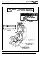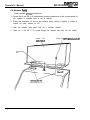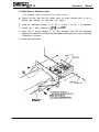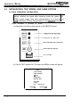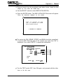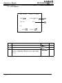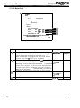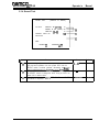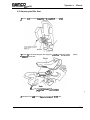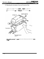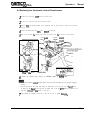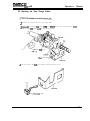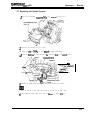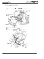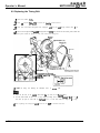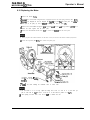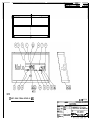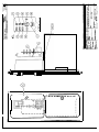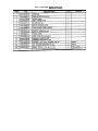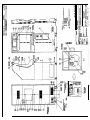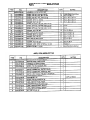
1
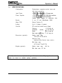
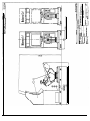
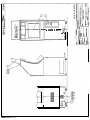
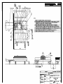
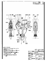
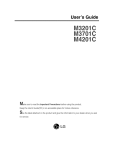
namcm
ODerator’s
MOTOCROSS GOITU SD
Manual
Table of Contents
1 .O SPECIFICATIONS ~1_1____--1__1-__11___-II-------------------------1
--l-_-___-____l-_--__-I----------I------ 2
1 .l Installed Dimensions
2
1.2 Convenience Kit ----1111-1--1----1-1----1----1----1-----1-----------------__-_-_1_____-1-____1_---y----------l----------------3
2.0 INTRODUCTION --------2.1 Game Description -------___--____-__I-_---------I---------------------- 3
3
2 . 2 G a m e R u l e s - - - - - - - - - - --1___1_______111____I---------I----------------------_1__1-____-1__-____1_----------I----I-------.-------4
3.0 PRECAUTIONS ----------3.1 Installation m_I-___m -____ - -__ - __-_-____-__-_-___-_------------------------- 4
4
3.2 Handling I_yy___-I_-I_-__I-___I---------------------------------------------3.3 player Safety -__-__- __-__________
---- _----_ - l_l_____ -- ____________ 6
4.6 lNSTAL~Tl()N --m-s _____-_-mm- __-_-l____-l_--_____-------------------------- 7
4.1 Lock plate Removal 1-1---1111---1
- _-_--__ - ________lll____l_____------7
-III-_I___-__I__I__-_-------------I----1-----------8
4.1 Marquee Assy
4.2 Bike Base to Monitor Tower -I___-___I___-----___I__-_-----------Iu 9
5.0 INITIALIZATION, TEST MODES AND GAME OPTIONS ---------------I----10
5 . 1 G a m e I n i t i a l i z a t i o n a n d M a i n M e n u - - - - - - - - - - - - - - - - - - - - 10
5.1.1 Coin Options ------ __-- IUmIm--- -----Y--------I-- 1 2
13
5 . 1 . 2 G a m e O p t i o n s - - - - - - - - - - - ---l-__-l__ll__--__-l_-----YI--mwm
___--___I_----_II_I_-14
5.1.3 l/O Test
5.1.3.1 Switch Test _____________ -l~~~----_-__~l-~~~~_ll----l---~-~~~ 15
5.1.3.2 Motor Test I____II_I-_---I__u-I_-II----------- 1 6
17
5.1.4 S o u n d T e s t - - - --_---I___--_--_---__________I_
-~II~-u_--Y~~--~~~~~18
5.1.5 M o n i t o r T e s t - - - - - - - -
5.1.6 ADS Data ----1-11 I-_I-__--I___---I---_----I------19
5.1 J Others Test --lll.l--l-. _l_--l__-____ll_l-_l-------l------l--- 19
5.2 Linked Operation __111____1__----_-1_---1---111----------------------20
22
6.0 MAINTENANCE wp-lsm-l-l I_-- -u_II--____-_I___-___-I
--------l---l
111---I---.35
TROUBLESHOOTING ILLUSTRATIONS AND PARTS LISTS
WIRING DIAGRAM
namco-
Operator’s Manual
MOTOCROSS GOP SD
1.0
SPECIFICATIONS
Configuration:
Single-player, separate monitor tower and
bike base assemblies
Input Power:
1 lo-125 VAC, 50160 Hz, 8 Amps max
Power Supplies:
(1 ea.) +5V and +I 2VDC 200 Watt switcher
(1 ea.) +3,3VDC 75 Watt switcher
Isolated power supplies for audio/motor drive
Monitor:
(1 ea.) 27 inch Wells-Gardner K7400
Game PCB:
Namco System 23
Linking:
Up to 4 players (4 games)
Controls:
DC motorized handle assy (Happ)
Steering:
1 k 60 deg. pot
Accelerator
(throttle): 1 k 270 deg. pot
Brake:
1 k 40 deg. pot
Bank angle: +I-15 deg., 1 k 40 deg. pot
Dimensions (packed):
Monitor tower assy:
35.5” W x 37” D x 83” H
Marquee Assy:
(packed within Monitor tower carton)
Bike base assy:
60” W x 41” D x 47.5” H
Weights (packed):
Monitor
tower
assy:
448 Ibs
Bike base assy: 315 Ibs
Note: Specifications are subject to change without prior notice. Shipping dimensions and
weights are based on standard packing specification.
Operator’s Manual
1.1
1.2
name=
MOTOCROSS GO!TM SD
Installed Dimensions
Convenience Kit (Included with Game Cabinet)
namco
MOTOCROSS GOP SD
2.0
Operator’s Manual
INTRODUCTION
2.1 Game Description
Motocross Go! SD is a motorcycle racing game, linkable by up to 4 players, offering
competition on either a one-way (going/coming) undulating course or a round
course for two or more players.
Turning is accomplished by leaning the bike left or right. The handlebar is used to
make a small adjustment to the bike’s direction and to provide counter steering.
Accelerator and brake controls are provided on the handle assy.
2.2 Game Rules
.
.
.
The player needs to reach the goal as fast as possible within the time limit.
Players choose from three courses and select either of two bikes. In
Communication (linked) mode, the course is decided by a majority of players.
The game continues until the time runs out. In linked mode, if one of the players
participating in the same race passes the check point, time is extended.
Operator’s Manual
3.0
name0
MOTOCROSS GO!TM SD
PRECAUTIONS
3.1 Installation
This game is designed for indoor use only. The following conditions must be
met:
1. The game location must be free of direct exposure to sunlight, high humidity,
dust, high heat or extreme cold. If installed in an unusually hot location, allow
additional clearance between the rear of the game cabinet and any structure
which would tend to restrict air circulation.
Do not install in an area such that the game would present an obstacle in
case of an emergency (i.e., near fire equipment or emergency exits).
2. Vibration. Due to the considerable accelerations produced on the ride base by
the player, it is very important to make sure that both the cabinet/bike
attachment bolts and the leg levelers are installed and tightened prior to
operation.
3. Before operating the game, make sure that the main AC power hookup includes
a safety ground. This will ensure safe operation as well as compliance with the
applicable FCC and UL requirements.
4. Measure the AC line voltage [LINE to GND and LINE to NEUT] and verify that it is
between 1 IO and 125VAC. NEUT to GND voltage should be less than 1 VAC.
3.2 Handling
1. Before replacing any parts, turn the AC power OFF and unplug the game.
2. Do not attempt to repair the Printed Circuit Boards (PCBs) on-site. They contain
sensitive integrated circuit chips that could be easily damaged, even by the
small internal voltage of a multimeter. Always return the PCBs to your
distributor for any repairs.
4
name=
Operator’s
MOTOCROSS GO!TM SD
Manual
3. The game monitor has areas of high voltage. Take care at all times to avoid
electrical shock whenever inspecting or adjusting the game. Before servicing
the monitor(s), make sure the game is unplugged.
Monitor
m Fly
back uansformet
4. Within the game cabinet ferrite clamps and shields have been included where
needed to control electric field emissions. Removal or relocation of either the
ferrites or shields will cause the FCC specification limits to be exceeded, and
may cause faulty operation of nearby susceptible equipment. Also, re-routing or
disconnection of grounds within the game system will result in excessive
emissions and/or a safety hazard.
5. Always return levelers to the extreme up position before moving the game.
6. Always re-install the bike lock plates before moving the game.
7. Always separate the monitor tower and bike base assemblies before moving the
game.
name0
MOTOCROSS GO!TM SO
Operator’s Manual
3.3 Player Safety
WARNING
THE FEATURES SHOWN ARE INTENDED
TO PROTECT PLAYERS AGAINST INJURY.
REPLACE ANY DAMAGED OR MISSING PARTS.
/
i
6
DECAL,
INSTRUCTION
MX40-07061-00
namco
Ooerator’s Manual
MOTOCROSS GO!” SD
4.0
INSTALLATION
4.1 Lock Plate Removal
FOR PROTECTION OF THE BIKE, THE LOCK PLATES ARE
INSTALLED PRIOR TO SHIPPING. THEY MUST BE REMOVED
BEFORE PLACING THE GAME INTO OPERATION. ALWAYS RE-
1. Remove the four M5 x 12 truss head philiips screws that attach cover plate (8)
to the bike base.
2. Remove the two M8 x 20 socket head flange screws (requires 6mm hex key).
3. Remove the two lock plates and secure them in the storage position as shown.
STORAGE
POSITION
FOR
LOCK
PLATES
nameo-
Operator’s Manual
MOTOCROSS GO!TM SD
4.2 Marquee Assy
Tools needed: phillips screwdriver
1. Locate the 2 ea. M6 x 40 attachment screws w/washers in the convenience kit
(Alt: installed in threaded holes in top of cabinet).
2. Place the marquee on top of the cabinet assy, tilting it slightly in order to
connect the cable harness at JP7.
3. Hook the marquee base panel over the 2 marquee brackets.
4. Install the 2 ea. M6 X 40 screws through the marquee base and into the cabinet.
MARQUEE
ASSY
MXcco7oSc-oo
a
SCREW, PAN HO PHIL, t.46 x 40 w,VdASHER
I
-----_
namca-
MOTOCROSS GO!T’ SD
Operator’s
Manual
4.3 Bike Base to Monitor Tower
Tools needed: 6mm hex wrench and leveler wrench
1. Position the bike base near the monitor tower as shown, allowing about a foot of
working area between the bike base and cabinet.
2. Locate the attachment hardware. (2 ea. M8 x 20 and 4 ea. M8 x 35 w/washers).
3. Connect the 2 cable harnesses at JPl9 and JP20.
4. Using care to prevent damage to the cable harnesses, push the two assemblies
together and install the attachment hardware, making sure to use the flat and
lockwashers provided.
5. Lower the leg levelers.
JP19 (12 PIN)
TOWER ASSY
BIKE &SE ASSY
nameo-
Operator’s Manual
5.0
MOTOCROSS GO!TM SO
INITIALIZATION, TEST MODES, AND GAME OPTIONS
5.1 Game Initialization and Main Menu
1
IMPORTANT
Always initialize the game after replacing either the game PCB,
ROMs, power supply, bike assy potentiometers, or at the time of
came installation. Perform this procedure in the seouence indicated.
1. System initialization is performed as follows:
a) Open the coin door to gain access to the SERVICE panel.
PUSHBUTTON SW. MOM. (ELK)
MINI-TOGGLE SW. SPDT (ON/OFF/ON)
045
TEST
e
TOGGLE SW. SPST (ON/OFF)
0
COIN
COUNTER
t
Service
Panel
b) Flip the TEST switch ON. The main test MENU screen will appear.
MENU
COIN OPTIONS
GAME OPTIONS
IV0 TEST
SOUND TEST
MONITOR TEST
ADS DATA
OTHERS
BIKE
ENTER: 0
L
10
INITIALIZATION
CHOOSE: AV
---___
namco-
Operator’s
MOTOCROSS GOIT’ SD
Manual
c) Remove hands from the accelerator and brake levers, stand the bike
straight up, and center the handle assy.
d) Use the SELECT switch to select BIKE INITIALIZATION.
e) Press the ENTER switch. The BIKE INITIALIZATION screen will appear.
Follow the instructions displayed on the monitor.
’ BIKE INITIALIZATION
RELEASE THE ACCELERATOR AND BRAKE
LEVER, PUT MOTORCYCLE AND STEERING
BACK TO ORIGINAL POSITION
5 SECONDS TO COMPLETE
9
The values for GAS, BRAKE, STEER, and BANK should be normalized
to around 0000. Exercise each of the controls and verify that “OK” is
displayed. If not, select “RETRY” to repeat the initialization.
BIKE lNlTlALlZ4TlON
lNlTlALlZ4TlON
COMPLETED
GAS
BRAKE
0000
0000
-
STEER
BANK
0000 C E N T E R 0000 C E N T E R -
(a)
(‘4
CC)
Cd)
RETRY
EXIT
ENTER: 0
CHOOSE: AV
g) Turn the TEST switch OFF, then ON again, and proceed with the other
items on the test menu.
name0
Operator’s Manual
MOTOCROSS GO!‘M SD
5.1 .l Coin Options
,
COIN OPTIONS
[DEFAULT
IN
GREEN]
GAME COST
4 COIN(S) 1 CREDIT
(a)
FREE PLAY
OFF
(‘9
EXIT
ENTER: 0
Item
CHOOSE: AV
Description
Number of coins required per game (1 credit)
1 - 9 COINS
(b)
Determines whether coin-up is required to play
ON/OFF
NOTE: When more than one game is linked, if GAME COST
is set to 9 COINS while FREE PLAY is set to ON, all linked
games are automatically accepted when one player makes
an entry.
12
Range
(a)
-m-.----
Default
2
OFF
- -
namco
MOTOCROSS GO!TM SD
ODerator’s M a n u a l
5.1.2 Game Options
3
f- G A M E O P T I O N S
(a)
(b)
ID NO. ;I;
TEAM COLOR
ENTRY TIME
FULL
COURSE
NOVICE
I-----D
L--e-.
B
1 LAP
DIFFICULTY
INTERMEDIATE
DIFFICULTY
ADVANCED DIFFICULl-f
._ - - - - - ..-
B
B
..-
CC)
Cd)
(e)
(0
(a
(h)
I.~
(1)
ti)
(k)
(0
(ml
Item /
Description
er on the far left is 1 the next one over is 2,
Range
1 Default
namco-
Operator’s Manual
MOTOCROSS GO!” SD
5.1.3 l/O Test
/MOlpla(a)
I
LINK ‘------I
~-----a .v (W
SWITCH
M
O
T
O
R
__+_
6
:
EXIT
ENTER: 0
Item
(4
(b)
(4
04
14
CHOOSE: AV
Description
The status of the DIP switch (SW4) on the CPU PCB is
displayed. Switches that are ON are highlighted in red.
The communication status between player positions is
displayed. When operating in linked mode, LINK ON “n” i s
shown, where “n” is the number of connected units (l-4). If
LINK OFF is displayed, the player unit is not receiving data
from the other linked units. LINK NG is displayed when
there is a data error between units. If either NG or OFF is
encountered, the PCB ID number should be checked in the
GAME OPTIONS menu (the left player should be 1, the neXt
one should be 2. and so on). The link cable in the back of
the game needs to be installed in order to communicate with
neighboring units. (See Linked Operation).
Provides a test screen for the checkout of the game’s
switches and potentiometers.
Provides a test screen for the checkout of the forcefeedback Handle motor.
Range
Default
ON/OFF
OFF
(all)
OFF
ON (14)
OFF
NG
-
-
-
- - - - - _ -
-_-_--_
____--_
name0
MOTOCROSS GO!TM SD
ODerator’s Manual
5.1.3.1 Switch Test
F
I/O TEST
DIP 4
12345678
L I N K L-----r
‘------I
SWITCH
GAS: 0000
BRAKE : 0000
STEER : 0000
(4
63
Cc)
BANK: 0000
TEST: ON
COIN: OFF T
W
L
Item
(a)
(b)
(cl
Cd)
(e)
SERVICE:
OFF
VIEW:
0 :
A :
V
:
-
OFF OFF OFF OFF
TO EXIT, PUSH OAND A
-
(1 9
Description
Value increases (+) as the accelerator (throttle) is rotated.
OK should be disolaved
at an angle less than full throttle.
Value increases (-) as the brake lever is pulled.
OK should be displayed at less than maximum brake angle.
Value increases (+) as the handle is rotated to the right.
Value increases (-) as the handle is rotated to the left.
CENTER is displayed at the neutral position.
Value increases (+) as the bike is leaned to the right.
Value increase (-) as the bike is leaned to the left.
/ CENTER is disblayed at the neutral position (straight up).
1 Allows each switch to be tested. TEST is ON in Test Mode.
1
ON/OFF
/ OFF
Operator’s
name=
Manual
MOTOCROSS GO!TM SD
5.1.3.2 Motor Test
r
I/O TEST
DIP 4
12345676
LINK ‘------I
c----.4
SWITCH
MOTOR
NONE OPERATION
STEER
BANK
OFF + 00 2 00 OFF 2 00 + 00 -
UP-DOWN OFF FR
-
(a)
(b)
(C)
Cd)
PUSH VIEWGHANGE BUTfON FOR NEXT OPTION
TO EXIT, SELECT NONE OPERATION AND PUSH 0
Item 1
Description
(a
Provides a non-operating mode for the purpose of getting
ready for the motor test. The technician should get on the
bike and center the handle before proceeding to (b). If
NONE OPERATION is highlighted while the ENTER switch
is pressed, the main 110 TEST screen reappears.
From (a), press the view change button to cell up the STEER
(handle) test. The force-feedback motor produces a torque
alternating in the left and right directions.
If operating
normally, ON is displayed. If the motor drive signal produces
an angular output which is determined to be out of tolerance,
This indicates the need to
ERR will be displayed.
troubleshoot the handle drive mechanism or angular sensor.
DX MODEL ONLY: tests the BANK actuator as in (b).
(‘4
DX MODEL ONLY: tests the air springs.
(a)
(b)
Range
__---___
OFF;
ON +/-00
ERR
OFF;
ON +I-00
ERR
OFF
ONF,R
16
1Default
NONE
OPERATION
OFF
to FF;
OFF
to FF;
OFF
namco-
Operator’s
MOTOCROSS GO!lM SD
Manual
5.1.4 Sound Test
SOUND
[DEFAULT IN GREEN]
TEST
I
VOLUME
FRONT L SP (00-65)
4 0 --L
FRONT R SP (00-65) 40
40
TANK SP (00-65)
REQUEST SONG NO.
128
(a)
(b)
MESSAGE
Cc)
EXIT
ENTER: 0
CHOOSE: AV
I Item I
Description
(4
Separate settings adjust the audio output level on the left,
right and tank speakers from the system PCB. Use the
SELECT switch to adiust up/down. Secondary L.R volume
control potentiometers are iocated on the HP km PCBs.
Use the ENTER switch to select the digit to be changed, and
the SELECT switch to change the value. Song no. 000 is no
sound; 001 is stereo check.
During the stereo check (001) LEFT, RIGHT. and CENTER
are tested in sequence.
(b)
w
Range
00-65
000 - 199
_--____-__
/ Default 1
40
000
_-_---
name=
Operator’s Manual
MOTOCROSS GO!TM SD
5.1.5 Monitor Test
f
MONITOR
TEST
GRADATION PAlTERN
CROSSHATCH PATTERN (CRT)
C R O S S H A T C H PAiTERN ( P R O J )
WHITE WINDOW (H)
WHITE WINDOW (M)
W H I T E W I N D O W (L)
INTERLACE
PATTERN
VIEW ANGLE ADJUST (CRT)
VIEW ANGLE ADJUST (PROJ)
2% WHlTE
SELECT SW :CHOOSE
Gradation Pattern
Crosshatch Pattern
P-l
Crosshatch Pattern
[Projector]
White Window
[H, M. Ll
Interlace Pattern
View Angle Adjust
[CRT]
View Angle Adjust
[Projector]
Full White
18
ENTER SW ENTER
1Four bars (G, R. B, W from top to bottom) with 16 gradations each are
j displayed.
j Green Grid is displayed. Lines should be reasonably straight, undistorted
and uniformly bright-across screen,
White Grid is displayed. This can be used to check monitor convergence.
Slight non-convergence (R, G or B showing) is normal.
Used to check light output (contrast) of screen. WHITE [H] reading should
be 40 to 80 R-L. Monitor contrast adjustments can be made using the
remote monitor PCB located behind the service panel.
A pattern of line blocks is displayed, used for indication of vertical hold
adjustment. On the center pair of line blocks, the top line of the right block
of lines should be aligned with the space between the first and second
lines of the lefl block.
Green Screen, with black frame, used at factory to set the VERT height,
HORIZ width, and VERT/HORIZ
centering. Crosspoint should be in the
center of the screen. Horizontal width should be set for slight overscan. If
adjustments are required. use the controls on the remote monitor PCB
located behind the sen&ze panel.
Black Screen, with white frame. Crosspoint should be in center of screen.
Used to check White Screen light output. (Nominally 15-20 R-L).
MOTOCROSS GOP SD
Operator’s
Manual
5.1.6 ADS Data
Test screen(s) provide data on total time and play time with respect to the various
course/bike selections.
The accumulated data shall not be initialized upon power-off unless either RESET
DATA or BACKUP RAM INITIALIZE are performed on the OTHERS test screen.
5.1.7 Others Test
/
\
OTHERS
ROM1
Ver.
ROM2
Ver.
-4-4.
-,-+
CLOCK W/MM/DD
GEOMETRY TEST
VIDEO TEST
DAY OO:OO:oO
W
w
W
(e)
(0
POINT ROM CHECK
DATA ROM CHECK
BACKUP RAM INITIALIZE? t-fl6:
---EXIT
ENTER: 0
Item
CHOOSE: AV
k7)
I
Description
~ (4
I
(b)
03
(d)
(e, f)
(9)
Range
_--_-______--_
Displays the software version.
/ Displays the dock. To adjust the clock, select
year/month/day, hour/minute/second and adjust the value
using the SELECT switch. Press the ENTER switch to load
the adjusted value.
Performs the GEOMETRY test on the game PCB. OK is
displaved
at the end of the test.
Performs the VIDEO test on the game PCB. OK is displayed
at the end of the test.
Performs a test on the POINT ROM and DATA ROM.
When BACK UP RAM INITIALIZE is selected, the screen
presents a YES/NO choice. When YES is selected, followed
by ENTER, both the game option settings. potentiometer
offset, and game data are reset to their default values. After
inifializing
the backup memory, perform the game
initialization procedure.
I
----11111-
Default
_-______
I
/ Date
Of
Mfa
OKJNG
OK
OK/NG
OK
OWNG
YES/NO
OK
NO
Operator’s Manual
name0
MOTOCROSS GO!TM SD
5.2 Linked Operation
Up to four games can be operated in Communication (linked) mode.
1, Turn off the main AC power.
2. Remove the cord cover from the back of each of the units to be linked.
3. Locate the link cable supplied with each game’s convenience kit.
4. Connect the cables as shown below, and re-install the cord covers.
5. Turn on the power, and set each of the game’s PCB ID numbers as described in
the GAME OPTIONS section.
PAN HD PHIL. M4 x 10 (2 PL
COVER, CORD
MX10.071O4-m
W&n four unit3 are connecfed
CORD BOX ASSY
MXG5-O707S-m
name=
Operator’s Manual
MOTOCROSS GOITU SD
5.2 Linked Operation (continued)
Adjacent units can be bolted together as shown below.
1. Place the first game in position, with leg levelers down.
2. Install the 2 ride joint brackets on the first game, using half the M8 x 20
hardware supplied with the convenience kit, leaving the screws slightly loose.
3. Push the second game into position, and align the threaded holes in the bike
base with the holes in the ride joint brackets.
4. Install the remaining hardware, lower the leg levelers on the second game, then
tighten the screws.
BIKE BASE ASSY
SCREW, SKT HD, M8 x 20
w/FLAT AND LOCKWASHERS
MX10-07125-00 (2 PL)
21
namco-
Operator’s Manual
6.0
MOTOCROSS GO!TM SD
MAINTENANCE
6.1 Replacing the Bank Control Potentiometer
1 Remove foorcmss-headed tmss screws (MS x 12) to remove the cover plate (F).
2 Disconnect one connator, then loosen the Cap bolt (M4 x 12) to remove the control bmcket.
3
Remove the nut of the control, then renmve
4 Assemble
the
the control from the contml
bank control following the pro-zedom
bmcket.
above in reverse order.
0 Direct the flat side of the control shaft toward the double point (see the Ague above)
5 After replacing the bank control with a new one, be sure to initialize this unit.
22
name=
Operator’s
MOTOCROSS GO!TM SD
Manual
6.2 Replacing the Bike Seat
1 Remove two cross-headed truss screws (MS x It) to remove the air COWL
2 Remove two cmss-headed hexagonal bolts (equipped witi the flat and spring washers)
to remove the bike seat.
washers
cs.dhexagonal boll
(wirh the flat and spring wuhers) (MX .x 20)
3 Assemble the bike seat following the instmcrions
above in r~eycnc order.
23
nameo-
Operator’s Manual
MOTOCROSS GO!T” SD
6.3 Removing the Accelerator Cover and Connector Plate
1 Remove four cross-headed truss screws (1M5
x 12) to remove
2 Remove two cross-headed truss
x It) to remove the connector plate.
screws (M5
the accelerator cover.
Cross-headed tm.u screw
3
Assemble
Older.
24
the ,x~.&-ator cover and the connector plate following the procedure above in reverse
namco’
Operator’s
MOTOCROSS GO!T’ SD
Manual
6.4 Replacing the Accelerator Control Potentiometer
1 Remove the accelerator cover
2
and the connector plate,
Remove one connector from the accelerator control.
3 Remove hvo cross-and-pan-headed screws (equipped with the flat washer) to remove the accelerator
control bracket.
4 Loosen ooe double point (M4 x 5), then remove the spur gear.
5 Remove the nut fmm the control, then remove the control from the a c c e l e r a t o r c o n t r o l b r a c k e t .
Double wint
\Nut
Accelerator
conuol
of.& control/,.. .:,.co,tro’
Grip
Wkn the dmxtle
is wide open
When t h e hmttle is OFF
View from the A side
6
Assemble
the
accelerator
control
following
the instructions
above
in
reverse
order.
To fix the accelerator conrrol bracket, tighten the screw after checking to see if the gear engages
smoothly.
. Direct the flat side of the control shaft toward the double point of the spur gear (see the ti!&we above).
. To engage the grip base and the spur gear, the double point of the spur geu should be positioned at the
upper side (venical) when the throttle is wide open.
l
7
After replacing the accelerator control with a new one. be sure to initialize this
unit,
25
namco-
MOTOCROSS GO!T~ SD
Operator’s Manual
6.5 Replacing the Brake Control Potentiometer
1 Remove the accelerator cover and the connector plate.
2 Disconnect one
connector
3
Loosen one double point @43 x 5). then remove the brake control bmcket.
4
Remove the nut from the control
5 Install
l
the brake contxul
Direct the flat side of the
6 Affer replacing the brake
26
from the brake control.
IO
remove the control from the brake
following the instmctions
above in reverse
control bracket.
order.
control shaft toward the double point (see the figure above).
cootml with s new one, be sure to initialize this unit.
MOTOCROSS GO!T’ SD
Operator’s
Manual
6.6 Replacing the View Change Button
2 Disconnect one connector from the view- change button.
3
Remove hvo cross-headed truss screws (M5 x 12) to remove the box cover. Note that the box cover
should be pulled out together with the grip and the grip base.
as-headed
oxss screw
View-
change button
4 Press four clicks to pull out the view-change button from the box cover
View-change
button
27
namco-
MOTOCROSS GOITM
. SD
ODerator’s M a n u a l
6.6 Replacing the View Change Button (continued)
5 Assemble the view-change button following the instructions above in
.
l
reverse
order.
Securely hook the throttle spring over the grip base and the accelerator stopper.
To engage the grip base and the spur geu. the double point of the spur ge~u should be positioned at the
upper side (vertically) when the throttle is wide open
When the thmcde is OFF
View from the A side
6
28
After replacing the view-change button with P new one, be sure
to initialize this unit.
nameo-
Operator’s
MOTOCROSS GO!TM SD
6.7 Replacing the Handle Control
] Remove five cross-headed truss screvvs
(M5 x 12) to remove+ the pulley cover.
2 Disconnect one connector from the control.
3
Loosen one cap
bolt (M4 x 10). then temove the steering control bracket.
4 Remove tbe nut fium tbt control to remove the control from tbc steering contml b r a c k e t .
Cap bolts (M4 .x IO)
the cmmol
-
c
Nut of tt
5 Assemble the handle control following the instructions above in reverse order.
.
Direct the flat side of the control shaft toward the cap bolt (see the figure above).
6 After replacing the handle control with a new one, be sure
to initialize this
unit
Manual
ODerator’s
namca
MOTOCROSS GO!“.’ SD
Manual
6.8 Removing the Handle Assy
1 Remove five cross-headed vuss
30
screws (MS x 12) to remove the pulley cover.
2
Disconnect one connector from the connector
3
Remove two cap bolts (MS
holder.
x IO) to remove rhe connector holder.
name=
Operator’s
MOTOCROSS GO!TM SD
Manual
6.8 Removing the Handle Assy (continued)
4 Disconnect the ground
terminal and two connectors
5 Remove two seu of four flange sockets I:M~ x 20) to remove the hold plates (L) and (R). and the
handle Assy.
Handle Assy
Range socket
(MS x 20)
-
I
(with the flat and spring--.warhm) (~4 x IO)
kimctors
Flange socket
(MS I 20)
0 When you place the removed handle Assy on the flour or like. be sure
up (see the figure above).
6 Assemble the handle Assy following
the instructions above in reverse
7 After assembling the handle Assy. be sure t o i n i t i a l i z e t h i s u n i t .
to place it with
order.
the control side
name0
MOTOCROSS GO!IM SD
Operator’s Manual
6.9 Replacing the Timing Belt
1 Remove the handle Assy.
2 Loosen one cap bolt @I4 x 10) to remove the steering
3 Loosen four cross-headed hexagonal bolts (equipped
control bracket.
with t h e f l a t and spring washers) (M6
x 16).
4 Loosen one hexagonal nut and one hexagonal bolt (M6 x 50) which fix the motor plate. Slide the
motor plate toward the pulley (A) side, then remove the timing belt.
Pulley (A)
I
Belt tension: 7.5 CO 9.5 kgf
(with the flat &d SQring
@I6 x 16)
5
l
l
Install the timing belt following the instructions above in reverse
order.
Direct the flat side of the contml shaft toward the cap bolt (see the figure above).
The belt tension should be from 7.5 to 9.5 kgf. (Adjust the timing belt so that the flexurn is 1 .O to I .5
mm when you push its center with 0.5 kgf, and 2.0 to 1.5 mm when under the weight of 1 .O kgf.)
6 After replacing the timing belt with a new one. be sure t o i n i t i a l i z e t h i s u n i t .
32
namco
Operator’s Manual
MQTOCROSS GO!T” SD
6.10 Replacing the Motor
1 Remove the handle Assy.
2 Loosen
four cross-headed hexagonal bolts (equipped with the flat and spring washers) (M6
x 16).
3
Loosen
one hexagonal nut and one hexagonal bolt (M6 x 50) which fuc the motor plate. then slide
motor plate to the pulley (A) side to t-emovc the timing belt from the pulley (B).
4
Remove four c r o s s - h e a d e d hexagonal bolu (equipped with t h e f l a t and spring washers) (M6 x 16) to
remove the motor together with the motor plate.
5 Remove four flush-headed washer nuts (MS)
to remove the motor
the
from the motor place.
lmi
l
When you place the removed motor on the floor or like, do not face the motor brushes (two) down.
6 Loosen two cap bolts (M4 x 10). then remove the pulley (B).
Cross-headed hexagonal s bolt
(with the flat and spring wsshc
(M6 x Id)
7
l
Install
the motor following the instructions above in reverse order.
The belt tension is 7.5 to 9.5 kgf. (Adjust the timing belt so that it is bent 1.0 to 1.5 mm when you
push its center with 0.5 kgf, and that it is bent 2.0 to 2.5 mm under the pressure of 1.0 kg0
8 After replacing the motor with a new one. be sun to initialize this unit.
33
Operator’s Manual
34
namco
MOTOCROSS GO!lM SD
namco
Ooerator’s
MOTOCROSS GO!T” SD
Manual
Troubleshooting
of tol., 200W PS could be defective.
en bench testing 200W DVE power supply, it must be
Video is blank,
distorted,
scrolling, out of
focus,
oolors/backgrou
Id/text m i s s i n g .
(1)
PS which is located under top cover of main PCB
rack assy.
Problem with monitor. (1) Check AC connector at monitor. Verify voltage is
between 110 and 125VAC (pins 1 to 3). With power
off, check fuse FIOI on monitor chassis PC6 (250V
3.15A fast blow). If OK, check the RGB signal input
connector JP14. Check the other end (J7 13 pin
connector) on the main PCB rack assy. If all OK,
using oscilloscope veriv presence of analog RGB
and sync at J7 pins 1.2.3 and 13 w.r.t. pin 10 (gnd).
Check cable to monitor remote adjustment board;
check for damage to potentiometers on the board. If
all OK, or if fuse blows, swap monitor chassis PCB.
Note: if warrant service is required. contact Customer Serve
through your distributor. Use only replacement parts for W-G
model K7400.
namco
Operator’s Manual
MOTOCROSS GOITM SD
Troubleshooting
.,~iri~.p;
Video (cant).
Main PCB problem.
No audio.
output is too
low, or
distorted.
Output level is set too
low.
Defective speakers.
Cabinet speakers: loss
of signal. power supply
failure, or amplifier
failure.
Bike tank speaker:
loss of signal, power
supply failure. or
amplifier
failure.
36
Observe the behavior of the system as it goes
through self-test upon power-up. The test takes
about a minute to complete. Horizontal lines will
scroll vertically for a few seconds, followed by CPU,
RAM and ROM checks. At each of these stages
OK will be-~displayed
as the test isssuc.essfully
completed. Once completed, the attract mode
If either during the test a
screen will appear.
hangup is encountered, or at the end of the test the
attract mode screen fails to appear, the main PCB
needs to be checked.
Individual sneaker outout volume can be adiusted
If output’ from
in Test mode, SOUND TEST.
cabinet speakers only is still unsatisfactory, check
the VOL 1 and VOL 2 pots on the HP AMP PCB.
They should be adiusted fully CW. Verify that
jumpers JPI and JP2 are ins&d.
Using ohmmeter, test for open coil (4 ohms). Bike
tank speaker: on main PCB, disconnect 4-pin
connector JPI 1 and measure resistance across
pins 1 and 2. Cabinet speakers: disconnect 4-pin
connector J2 on HP AMP PCB. Left speaker
should provide 4 ohms across pins 182; r i g h t i s 4
ohms across pins 3&4. If an open reading is
obtained in anv case. venfv
continuitv of wirina to
speaker. If w&g is CK, replace speaker.
Verify continuity of wiring from the RCA jacks at
JIO on the main PCB to 54 on the HP AMP PCB.
Check AC input power to HP AMP PCB. Voltage
should be 24VAC across Jl p i n s 183. If a problem.
check wiring to 48V CT transformer Tl, and
primary vs secondary voltage. Primary should be
11OVAC. If primary but no secondary voltage,
replace transformer. If AC power is OK, and if
speakers are OK, check 2A fuses FlBF2 on HP
AMP PCB. If blown, this indicates a component
failure on the board: Replace PCB.
Check continuitv of wirina Rom the RCA iacks at J9
on the main PCB to the&pin connector JP33 on
the top side of the rack. Of the 2 RCA jacks, the
one feeding the white wire needs to be installed in
the white (left) jack of J9. Verify that 12VDC is
present at JPlOA pins 4 to 3 (6-pin brn connector
at top of main PCB rack. If OK, remove cover from
rack and check connections to the AMP PCB If
connections and power are good, replace PCB.
name=
Operator’s Manual
MOTOCROSS GO!TM SD
Troubleshooting
Symptom.. 125~. _) possible Cause : my :-: .rd .“tccelerator,
lank, brake,
steering
:ontrols are
offset or do not
.espond.
‘~2% ‘- ,:I. 2Solution
(1) System not initialized. (1) Especially after replacement of any component,
initialize the system: toggle the service panel Test
switch ON. Select BIKE INITIALIZATION from the
menu. Follow the on-screen instructions.
(2)
Excitation voltage to
potentiometers faulty,
or incorrect feedback
voltage.
(2)
Voltages and feedback to/from the entire bike can
be checked at the cabinet/bike interface connectors
JP19 and 20. (this will require the removal of the 6
bolts which join the cabinet to the bike). With JP19
and 20 connected, and with power on, check:
P Bank/steering pots, supply voltage:
ADVcc (JP19-5 wht/red) to GND (JP19-8 whffblk).
a Brakejaccel
pots supply voltage:
ADVcc (JP19-1 whffred) to GND (JP19-4 wht/blk).
l
Both readings should be 4.75 to 5.lOVDC. If
OK, check the pot wiper output (tolerance +I.SVDC):
q Steering (voltage at pin 2, with respect to 8)
25V (steering centered)
3.8V (max. right)
0.N (max. left)
o Accelerator (pin 3 with respect to 4)
1.8V (accel off)
4.2V (accel max. on)
q Brake (pin 6 with respect to 4)
2.6V (brake off)
05V (brake on)
o Bank (pin 7 with respect to 8)
2.6V (bike centered)
4.3V (max. right bank)
1 .OV (max. left bank)
.
If supply voltage to pots is low or OV,
d i s c o n n e c t JP19 and measure again on the
cabinet side of the plug. If no change. then
ASCA-3A
PCB assy needs repair. If supply
voltage is corrected once the load is removed,
or if voltages obtained from the pots are
incorrect, proceed with the resistance check of
pots/wiring on bike assy.
Oaerator’s
namco-
MOTOCROSS GOfTM
. SD
Manual
Troubleshooting
symptom :c
qccel, steering,
xaking or bank
:ontrols
lroblem
continued)
* _-‘(0 ( ; 4Ft&@!e;.Ciuse,,
,3)
Open pot, open or
pinched wire, or short
to ground on bike.
j/
,~,“1
I ;, y ,:~1.-“3*;~~~,so-~tio~~‘,~,
‘?‘.,
“* :, $+
With power off, using an ohmmeter, check the
following (bike side of harness at JPi9; all readings
+/-20%):
ADVcc load (accel, brake)
JP19 pins 1 & 4
500 ohms
q
P ADVcc load (steering, bank)
JP19 pins 5 & 8 500 ohms
o Accel. pot center terminal to ADVcc
JP19 pins 3 &I
440 C (throttle off),
0 R (max. throttle)
Brake pot center terminal to ADVcc
JPl9 pins 6 8 1 430 R (off), 560 R (on)
q
o Steering pot center terminal to ADVcc
JPl9 pins 2 & 5 460 R (centered),
260 R (max. right), 530 R (max. left)
o Bank pot center terminal to ADVcc
JP19 pins 7 & 5 460 Q (bike centered),
250 R (bank right), 620 R (bank left)
If the ADVcc load resistance is around 1 kC.
either one of the pots or the wiring to it is open.
Check each pin to ground: readings should be
open. If not, inspect for pinched wire on bike.
Center terminal readings must have the same
rotational sense as indicated above. If not, the
pot is wired up backwards.
If the readings are ambiguous, fail to change,
or fail to repeat as the control axis is rotated,
check the pot shaft set-screw. It could be
loose.
Recheck in TEST mode, I/O SWITCH test.
Verify OK readings can be obtained from
controls.
:4)
Communications error
between main PCB
and ASCA-3A
PCB.
Digitizing error.
‘5)
38
Check USB cable between main PCB Jll and
ASCA-3A PCB J102.
Repair ASCA-3A
assy.
name=
MOTOCROSS GO!T’” SD
Operator’s
Manual
Troubleshooting
-*
Symptom.. 2 ,,wPossible Cause
Feedback
(1) Feedback motor
failure, or
to motor.
steering does
not operate, is
sluggish, or
only goes one
way.
0
0
Units will not
link.
Monitor Screen
Data not visible
around edges.
Monitor colors
sre incorrect.
Jnusual or
ntermittent
video.
open
circuit
Drive belt loose or
broken.
No power to drive
board. or board failure.
0
PCB ID number
incorrectly set.
G-i
Loose or damaged link
cable.
0
VERT or HORZ
posittin or VERT size
out of adjustment.
RGB outputs are
faulty.
RGB inputs are faulty
Screen needs
degaussing.
Unstable power
SUPPlY.
0
0
0
0
0
Intermittent connection
in PCB rack.
0
PCB assembly is
overheating.
: _
SolutIonb
(1) -1 With power off, disconnect connector P9 from AMC
PCB. Measure resistance across pins 1 8 2. It
should be about 10.6R. If open, inspect wiring out
to motor on bike, including 5R 30W resistor which
is in series with the motor windings. If still open,
reolaoe motor. Check resistance between motor
wires and frame ground. If shorted, replace motor.
(2)
Check drive belt inside the bike handle assy.
(3)
With power on, verify the DC voltage at the AMC
PCB J3. Pins 3 to 8 should read 5VDC; pins 4 to 8
i s 12VDC. If not, check wiring to 200W power
SUPPlY.
With power on, check AC voltage at AMC PCB J8.
Should be 24VAC between pins 1 & 3. If not,
check 5 A fuse. If blown, AMC PCB or motor
needs repair.
(1)
See description under TEST mode, GAME
OPTIONS. If correct but problem persists, try
renumbering games from’right to left.
(2) 1If LINK NG is displayed in TEST mode, check
continuity of link cables from J3 on main PCB.
through the Transit PCB (mounted on cord box),
and to the adjacent game. If problem persists,
possible causes are Main PCB, Power PCB.
Transit PCB, or cable problem.
Adjust. (Monitor remote adjustment PCB).
Ref. Monitor Vendor Service Manual. Change
Measure power supply input to PCB 6-pin
connector. Pin 3 should be 5V +.2/-O with respect
Remove cover and reseat cards. If problem
persists, return to Namco for repair.
Ooerator’s
40
Manual
name0
MOTOCROSS GOfrM
. SD
namea
MOTOCROSS GOITM SD
ILLUSTRATIONS AND PARTS LISTS
Ot>erator’s
Manual
ASSY, OVERALL, MXOI -07073-00
NOTE:
1) INSERT GROUND TERMINAL BETWEEN B2 & B3.
NLTD
Iy em*
5
(I 24741500
uxos-07080-00
I.".
I
7
ASSY, BASE, BIKE, MX05-07113-00
t i+u
\
I \
I
I
I
\
l
U
I
I
I
qo-ooo
Ii0 0
:
\
0 0
0
0
q o -Goo00
0 0000 00 0
,b
/
/
I
/
9 a,
ASSY, MARQUEE, MX05-07080-00
4
P
NLTD
#
24741300
-OUTSIDE REAR OF CABINET
ASSY. CORD BOX
namco
MOTOCROSS GOP SD
2.0
Operator’s Manual
INTRODUCTION
2.1 Game Description
Motocross Go! SD is a motorcycle racing game, linkable by up to 4 players, offering
competition on either a one-way (going/coming) undulating course or a round
course for two or more players.
Turning is accomplished by leaning the bike left or right. The handlebar is used to
make a small adjustment to the bike’s direction and to provide counter steering.
Accelerator and brake controls are provided on the handle assy.
2.2 Game Rules
.
.
.
The player needs to reach the goal as fast as possible within the time limit.
Players choose from three courses and select either of two bikes. In
Communication (linked) mode, the course is decided by a majority of players.
The game continues until the time runs out. In linked mode, if one of the players
participating in the same race passes the check point, time is extended.
ASSY, COMPONENT SHELF, MX05-07079-00
1
I
I
L
c
I
/
J
I
/
-sGY----,---*
I
I
I
_--- __---e
I
]
1 '\
I
I
L-------4
C----------J
J
ASSY, CORD BOX, MX05-07078-00
_____--__-__--..-.I-..-.
__-_--
_____-_-_-_
ASSY, MONITOR TOWER, MX05-07076-00
---. .
ASSY, RIDE, MX05-07075-00
e--- .
r
996.4 REF
L
1
880 R E F
270 REF
1180 REF
NOTE:
I, REFER TO THE HANDLE ASS” URAVI~ HX05-07172-M) FOR HINUE W.MTIffi HARDVARC.
NI Tll ” ?4742001
ASSY, MONITOR TOWER, MX05-0707640
I
ASSY,
IDECAL.
BIKE, MX05-07114-00
NUMBER PLATE.
FLAMES. RIGHT
1
I
BODY, BIKE
MX10-07213-00
1
I
3,
1VG17473220(
1
I
13 BOND, ADHESIVE (1401)
IMx4ao7123-00
MX40-07123-01
ADJUSTER (F)
I D E :CAL. TANK, UPPER, LEFT
1
.
I
1
1
1
1
AIR
1
MX40-07070-00
ECAL. TANK, UPPER, RIGHT
DECAL, TANK, BLACK, LEFT
1
1
h4X40-07070-01
DECAL, TANK, BLACK, RIGHT
1
MX40-07173-00
DECAL, NUMBER PLATE, FLAMES, LEFT
1
D
ASSEMBLY PROCEDURES
PASS (27). BELLOWS, THROUGH (1). BIKE FRAME, AND ATTACH
(1) TO THE BIKE BASE ASSY
ATTACH (2). PULLEY COVER BKT, (16), BIKE BODY, (4). SIDE BKT,
(3). ENGINE BKT, IN THAT ORDER
TEMPORARILY SECURE (24 8 25b ENGINE COVER L&R
ATTACH (27). BELLOWS, TO ENGINE COVER LE,R. AFTER THAT
TIGHTEN THE ENGINE COVERS
EXCLUDE (26). COVER FRONT, ATTACH OTHER PARTS
ATTACH (26) AFTER INSTALLATION OF HANDLE ASSY
NLTD # 24742200
ASSY, BIKE, MX05-07114-00
J A N
ZB ‘99
E3:43
HANDLE ASSY
48
FROtl
TO
16302382244
PQGE.003/086
namccT
.
,f--.
MOWCROSS GOP DX
HANDLE ASSY - PARTS LIST
ojJw+tcx%
Manual
Operator’s Manual
HANDLE ASSY (continued)
namco
GOP DX
MOTOCROSS
namcer
MOTOCROSS GOP OX
b”
n.
Ope&o@sIManual
HANDLE ASSY - PARTS LIST (continued)
*ax TOTFlL
P R G E . 0 0 6
**
//,
/,,
I
I
I
III