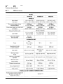
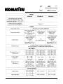
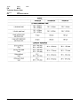
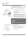
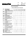
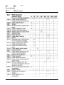
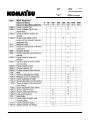
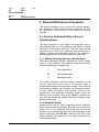
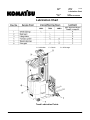
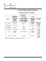
1
F-code
PS
Section
C-code
M2.0
Technical Service Data
Version no
003
T-code
395/396/397/398/399
Technical Service Data
! WARNING
© Komatsu Forklift U.S.A., Inc.
Master Service Manual
When the battery is fully charged,
performance may vary due to motor and
system efficiency tolerance. Technical
service data represents nominal values
obtained under typical operating conditions.
Specifications are subject to change
without notice.
2001-09-18
57
F-code
Section
C-code
M2.0
PS
Technical Service Data
Version no
T-code
003
395/396/397/398/399
58
Master Service Manual
2001-09-18
F-code
PS
Version no
003
© Komatsu Forklift U.S.A., Inc.
Master Service Manual
2001-09-18
Section
C-code
M2.0
Technical Service Data
T-code
395/396/397/398/399
59
F-code
Section
C-code
M2.0
PS
Technical Service Data
Version no
T-code
003
395/396/397/398/399
60
Master Service Manual
2001-09-18
F-code
PS
Version no
Section
C-code
M3.0
Ordering Spare Parts
T-code
001
Ordering Spare Parts
1. Locate fault on truck.
2. Identify truck model, serial number, and battery voltage.
3. Locate page with the exploded diagram and find the
item number for the part required.
4. Locate item number in table. Select the column for
actual truck model and serial number. The following is
an explanation of a serial number,
* 2 = FR18S-2A, FR23S-2A; 3 = FR15DR-2A
** 4 = 24 volt; 6 = 35 volts
*** 7 = 1997, 8 = 1998, etc.
**** 1 = 198_, 2 = 199_, 3 = 200_
***** FRS = FR18S-2A & FR23S-2A;
FRD = FR15DR-2A
! CAUTION
Although some trucks appear to be similar,
component parts may not be interchangeable.
If an incorrect part is used, the truck may
malfunction.
5. Note part number.
6. Call your local Komatsu Forklift Dealer and state the
part number.
7. If truck model, serial number, or article number cannot
be found, call your local Komatsu Forklift Dealer for
assistance.
© Komatsu Forklift U.S.A., Inc.
Master Service Manual
2000-08-04
61
F-code
PS
Version no
Section
C-code
P
Contents, Section P
T-code
000
Contents, Section P
1. Planned Maintenance
© Komatsu Forklift U.S.A., Inc.
P1.0
INTRODUCTION, MAINTENANCE
P2.0
SERVICE SCHEDULE
P3.0
LUBRICATION CHART
P4.0
OIL AND GREASE SPECIFICATIONS
Master Service Manual
2000-08-04
63
F-code
PS
Section
C-code
P1.0
Introduction, Maintenance
Version no
T-code
000
Introduction, Maintenance
The schedules of maintenance and lubrication given in this
section of the Service Manual cover up to one year ’s
operation of a truck. These schedules are based on hourly
usage and can be adapted to suit most normal one shift
patterns. The following hourly usage figures have been used
when calculating the schedule:
Single shift, 30 hours per week usage
Double shift, 60 hours per week usage
Triple shift, 90 hours per week usage
The schedules are intended only as a guide, not as a rigid
structure. Operators of trucks may wish to adapt them to local
requirements; but it is emphasized that the schedules
represent minimum manufacturer requirements, and all items
should be included in a service program to ensure minimum
downtime and a high safety status of the equipment.
l Use only spare parts approved by Komatsu
Forklift.
l Always clean the equipment and carry out a full
safety check after service.
© Komatsu Forklift U.S.A., Inc.
Master Service Manual
2000-08-04
65
F-code
Section
C-code
P1.0
PS
Introduction, Maintenance
Version no
T-code
000
1. Jacking Truck Off The Floor
To perform maintenance that requires the truck to be lifted
from the floor, observe the proper safety precautions as
follows:
1. Lower the forks completely. Remove any load.
2. Turn key switch OFF and disconnect battery
connector from the truck.
3. If possible, stabilize the top of the mast with an
overhead chain hoist.
4. Before jacking the truck, check the stop block and
adjustment bolt on the pivot plate to make sure
they are in good condition. If the block or
adjustment bolt are excessively worn or missing,
take the truck out of service and contact your local
Komatsu Forklift Product Support Representative.
! WARNING
Use extreme care whenever the truck is
jacked up for any reason. Never block the
truck between the mast column and floor.
Use a suitable hoist to stabilize the mast.
Keep hands and feet clear from beneath
truck while jacking. Use jack stands or solid
blocks to support the truck, do not rely on
jacks.
5. Place the jack under the designated jacking points.
1.1. Elevate Rear of Truck
1. Place the jack in the designated jacking position.
2. Jack the rear of the truck so the drive tire is off the
floor no more than 3 inches (76 mm).
3. Block truck in place.
66
Master Service Manual
2000-08-04
F-code
PS
Section
C-code
P1.0
Introduction, Maintenance
Version no
T-code
000
1.2. Elevate Either Side of Truck
1. Place the jack in the designated jacking position.
2. Jack the side of the truck so that the load wheel is
off the floor no more than 0.50 inch (12.7 mm).
3. Block truck in place.
© Komatsu Forklift U.S.A., Inc.
Master Service Manual
2000-08-04
67
F-code
Section
C-code
P1.0
PS
Introduction, Maintenance
Version no
T-code
000
2. Lubricants
2.1. Standard
For reach trucks in their standard design under continuous
operation, the recommended ambient temperature is 23° F (5° C). These trucks should apply to the following guidelines:
l Parked outside storage when not in use
l Charging and maintenance work to be done
outside storage
2.2. Corrosion
In an environment where a damp, wet, or corrosive condition
exits, these trucks apply to the following guidelines:
l All hardware coated with LPS Rust Inhibitor
during and/or after assembly
l Sealed components (switches, push/pull
cables, sensors, etc.) where appropriate
l Grease fittings provided on axle and other pivot
points
l Plated pins, shafts and linkage where required
l All electrical connections coated with Dow
Corning No. 4 compound during assembly
l Lift chains coated with Libriplate chain
protectant
l Components coated with LPS Cold Galvanize
where appropriate
l Components (adjustable features, bearing
races, etc.) coated with Antisieze where
appropriate
2.3. Cold Storage
To prevent moisture contamination in the electrical system,
trucks equipped with cold storage conditioning packages
have electrical compound applied to all electrical connections
during assembly. For cold storage reach trucks with
continuous operation, the recommended ambient
temperature is 5° F (-15° C). Cold storage trucks should apply
to the following guidelines:
68
Master Service Manual
2000-08-04
F-code
PS
Version no
Section
C-code
P1.0
Introduction, Maintenance
T-code
000
l
l
l
l
Trucks completely dry prior to commencing the
continuous stay in the cold storage
Parked inside the cold storage for operator
breaks
Charging and maintenance work done outside
the cold storage
Trucks completely dry before returning to
continuous cold storage operation
For cold storage reach trucks with intermittent operation, the
recommended ambient temperature is - 13° F (-25° C). Trucks
apply to the following guidelines:
l Surface condensation occurs, “wet” trucks
should neither remain idle in the cold storage
for no longer than 10 minutes nor operate inside
the cold storage for extended periods
l Condensation must not be allowed to freeze on
the truck at any time
l Park outside the cold storage for operator
breaks
l Charging and maintenance work to be done
outside the cold storage
Items included in the cold storage package are as follows:
l All corrosion conditioning items
l Sealed components used in all non-heated
locations
l Heavy-duty mechanical switches used where
appropriate
l Thermostat controlled heaters used to prevent
moisture buildup in electrical component areas
l Heaters located around the electronic card, the
drive and lift power controllers, the steering
tachometer, and hydraulic control
potentiometers
l Windshield replaced with a screen
l Hydraulic fluid in lift/auxiliary system changed to
ATF
l Anti-seize compound used on the control
console, vertical adjustment bar
l Standard grease replaced with Mobiltemp SHC
32 lubricating grease
© Komatsu Forklift U.S.A., Inc.
Master Service Manual
2000-08-04
69
F-code
Section
C-code
P1.0
PS
Introduction, Maintenance
Version no
T-code
000
2.4. Freezer Storage
To prevent moisture contamination in the electrical system,
trucks equipped with freezer storage conditioning packages
have electrical compound applied to all electrical connections
during assembly. For freezer storage reach trucks with
continuous operation, the recommended ambient
temperature is -31° F (-35° C). Trucks should apply to the
following guidelines:
l Trucks must be parked inside the freezer for
operator breaks
l Trucks stay in the freezer during battery
charging or change-out (If truck is removed
from freezer for maintenance work or battery
charging, it must be completely dry before
reentering the continuous shift in the freezer)
Items included in the freezer storage package are as follows:
l All cold storage items contained
l Transmission fluid in the lift/auxiliary system will
be changed to Texaco 15
l Cooling fan in the component compartment will
be disconnected.
70
Master Service Manual
2000-08-04
F-code
Section
PS
P2.0
Service Schedule
Version no
002
C-code
T-code
395/396/397/398/399
Service Schedule
1. Planned Maintenance Schedule
© Komatsu Forklift U.S.A., Inc.
Master Service Manual
2000-08-04
71
F-code
Section
C-code
P2.0
PS
Service Schedule
Version no
T-code
002
395/396/397/398/399
72
Master Service Manual
2000-08-04
F-code
Section
PS
P2.0
Service Schedule
Version no
002
© Komatsu Forklift U.S.A., Inc.
Master Service Manual
2000-08-04
C-code
T-code
395/396/397/398/399
73
F-code
Section
C-code
P2.0
PS
Service Schedule
Version no
T-code
002
395/396/397/398/399
74
Master Service Manual
2000-08-04
F-code
Section
PS
P2.0
Service Schedule
Version no
002
© Komatsu Forklift U.S.A., Inc.
Master Service Manual
2000-08-04
C-code
T-code
395/396/397/398/399
75
F-code
Section
C-code
P2.0
PS
Service Schedule
Version no
T-code
002
395/396/397/398/399
2. Planned Maintenance Procedures
This section describes how to perform the services listed in
the Schedule of Planned Maintenance Operations. As with
the “Schedule”, this section is subdivided into service
intervals.
2.1. Services Performed Daily or Every 8
Operating Hours
The daily inspection is to be made by the operator prior to
each operating shift. It is the operator’s responsibility to report
any defects to the proper authorities. The truck should not be
operated until it has been inspected and repaired by a
trained, qualified, and authorized technician. The operator is
ultimately responsible for the safe operation of reach truck.
2.1.1. Battery Discharge Indicator with slow down
The battery discharge indicator indicates the current charge
status of truck’s battery. (See “Battery Discharge Indicator
Parameter Adjustment” on page 384.)
1
1/2
0
Full charge battery
Half charged battery
Discharged battery
The battery discharge indicator has an integrated cut-out
function that slows down truck’s lift function when a
predetermined charge level has been reached. This prevents
overloading the battery and increases the operating economy
of truck. When the battery has reached a charge level
equivalent to 70% discharge, a warning signal is given via
flashing lights. A further 10% of the battery’s capacity can
then be used before the battery discharge indicator slows
down the lift function.
2.1.2. Hydraulic System
Inspect entire truck for leaks, especially around hydraulic
pump assembly and lift cylinders. Any sign of oil on the floor
under truck is an indication that truck may be leaking
hydraulic oil or transmission fluid. Report any problems to the
proper authorities, and DO NOT operate truck until it has
been inspected and repaired by a trained, qualified, and
authorized technician.
76
Master Service Manual
2000-08-04
F-code
Section
PS
P2.0
Service Schedule
Version no
002
C-code
T-code
395/396/397/398/399
2.1.3. Frame/Sheet Metal
Inspect truck for loose, damaged or missing parts. All shields
must be in place and functional. Report any problems to the
proper authorities. DO NOT operate truck until it has been
inspected and repaired by a trained, qualified, and authorized
technician.
2.1.4. Wheels/Tires
Inspect wheels and tires for wear and damage. Trash that is
wrapped around wheels and axles will cause premature tire
wear and bearing damage. The floors should be kept clear of
trash to prevent damage to wheels and tires.
2.1.5. Functions/Operations
Test truck for the proper operation of all functions including
the travel controls, lift and lower functions, brakes, and
emergency disconnect button. Safety devices must be
operational. Report any problems to the proper supervisors.
DO NOT operate truck until it has been inspected and
repaired by a trained, qualified, and authorized technician.
2.2. Services Performed Monthly or Every
120 Operating Hours
The monthly planned maintenance service should be
performed by a trained, qualified, and authorized technician.
2.2.1. Inspection
All services and inspections listed above for the daily
inspection should be performed at this time. The inspection
procedure should be more thorough, and minor deficiencies
should be corrected.
2.2.2. Transmission
Inspect for oil leakage.
2.2.3. Brakes
When the foot is lifted from the brake pedal it should stop a
fully loaded truck at full speed in approximately one truck
length.
© Komatsu Forklift U.S.A., Inc.
Master Service Manual
2000-08-04
77
F-code
Section
C-code
P2.0
PS
Service Schedule
Version no
T-code
002
395/396/397/398/399
2.2.4. Battery
Contact your battery dealer for specific instructions on care
and maintenance of the battery. An average battery will have
a specific gravity of 1.170 at the 80% discharged level.
However, there are many different batteries on the market.
Only the battery manufacturer can accurately determine the
fully charged and 80% charged levels. Contact the battery
manufacturer for this information.
2.2.5. Electrical Connections
Check that all electrical connections are clean and tight. Plugin connectors should be unplugged and plugged back in to
clean terminals. If the truck is equipped with any of the coldstorage, freezer use, or corrosive environment application
packages, the di-electric compound in the plug-in connectors
should be renewed.
2.2.6. Contactor Tips (NOT Sealed)
Inspect contactor tips for arcing, pitting, or burning. Minor
pitting of the tips is not a problem. However, if tips are pitted
through the tip to the copper bar, tips should be replaced. DO
NOT file tips. Replace tips only in complete sets. Some
contactors have concealed tips or fully sealed so tips cannot
be replaced.
2.2.7. Motor Brushes
The drive motor and pump motor are equipped with a brush
wear sensor which will indicate when brushes need replacing.
For minimum brush length see page 57. As a rule of thumb,
brushes should be replaced if brush spring is within 0.0625
inch (1.59 mm) of touching brush holder.
2.2.8. Drive Motor
Blow out drive motor fan and vents. Check for any signs of oil
on drive motor fan and air vents. Check for any damage to
fan or air vents.
! WARNING
78
Compressed air used for cleaning MUST
be reduced to less than 30 psi (206 kPa)
and then only with effective chip-guarding
and personal protective equipment worn.
Master Service Manual
2000-08-04
F-code
Section
PS
P2.0
Service Schedule
Version no
002
C-code
T-code
395/396/397/398/399
2.2.9. Hydraulic Reservoir
Check fluid level in the hydraulic reservoir.
2.2.10. Frame Lube
The pressure type grease fittings (zerk fittings) should be
lubricated with grease (see page 84). The total number of
grease fittings depends on truck options when built (see
page 83). A truck with a cold-storage, freezer use, or
corrosive environment application package will have more
grease fittings than a standard truck. Look for flush-type
grease fittings on the load wheel axles. Regular fittings may
be found on the transmission mounting bearing and mast
chain sheave shafts.
2.2.11. Pivot Points
There are pivot points and other items that need to be
lubricated but do not have grease fittings. Lubricate these
non-greasable wear points with a drip oil can using 10 weight
machine oil.
© Komatsu Forklift U.S.A., Inc.
Master Service Manual
2000-08-04
79
F-code
Section
C-code
P2.0
PS
Service Schedule
Version no
T-code
002
395/396/397/398/399
2.3. Services Performed Every 480 or 960
Operating Hours
The planned maintenance service should be performed by a
trained, qualified, and authorized technician.
2.3.1. Drive Motor
Since the operating environment of material handling
equipment varies widely, the following recommendations are
suggested for periodic maintenance inspections for the drive
motor armature.
l
Normal Service 8 hours per day operation
l
Routine inspection every 960 hours (8 months).
l
Severe Service 24 hours of daily operation
1. Dusty or sandy locations; such as a cement plant,
lumber or flour mills, coal dust or stone-crushing
areas.
2. High temperature areas; such as steel mills,
foundries, etc.
3. Sudden temperature changes (continuous in-dooroutdoor movement) that is refrigeration plant, etc.
l
80
Routine inspection every 480 hours (4 months).
Master Service Manual
2000-08-04
F-code
Section
PS
P2.0
Service Schedule
Version no
002
C-code
T-code
395/396/397/398/399
2.4. Services Performed Annually or Every
1440 Operating Hours
The annual planned maintenance service will take a longer
period of time to complete than does the monthly service.
This would be a good time to arrange other repairs that have
been noted on the monthly service.
2.4.1. Inspection
All services and inspections listed for the daily and monthly
inspection should be performed at this time. The inspection
procedure should be more thorough, and minor deficiencies
should be corrected.
2.4.2. Transmission
The transmission fluid should be drained once a year. The
drain port is located on the lower portion of the side cover
opposite the drive tire. Remove bolt to drain transmission
fluid. Flush transmission case. Pour a clean solution into the
fill port accessed from the battery compartment. With the
drive tire off the floor, allow solution to run out of drain port
while transmission is running. Stop flushing when the solution
runs clean. Allow the solution to drain well before replacing
drain plug bolt. Replace drain plug bolt. Refill transmission
with proper clean oil before operating truck.
2.4.3. Battery
At approximately 1500 hours, contact an authorized battery
dealer to determine the overall condition of the battery.
Determine if the battery needs to be washed down. This can
only be done by properly trained, qualified, and authorized
technician.
© Komatsu Forklift U.S.A., Inc.
Master Service Manual
2000-08-04
81
F-code
Section
C-code
P2.0
PS
Service Schedule
Version no
T-code
002
395/396/397/398/399
2.4.4. Hydraulic System
The hydraulic system should be drained, flushed and refilled,
and the pressure relief valve setting should be checked and
adjusted. This will maintain proper lubrication properties
within the system.
! WARNING
Before siphoning oil from reservoir, make
certain siphon is clean.
To drain reservoir, remove reservoir filter assembly. Siphon
oil from reservoir and purge oil out of hydraulic system. Fill
reservoir with proper clean oil. Operate the raise and lower
function several times to purge air from the system. Check oil
level. Put rated truck capacity load on forks and adjust
pressure relief valve, if necessary, so that truck will lift rated
load.
2.4.5. Brakes
Follow procedures for brake removal before inspecting.
Remove brake assembly and inspect friction disc for wear.
The friction disc should be replaced once thickness is 0.25
inch (6 mm) or less. The armature and magnetic coil should
be adjusted if machine will not meet stopping and holding
specifications. The air gap should not exceed 0.018 inch
(0.46 mm) and should remain within 0.003 inch (0.076 mm)
throughout the circumference.
2.4.6. Lift and Carriage Chains
Lift and carriage chains should be checked every 720 hours.
A chain gauge should be used to check stretch of the links.
To adjust inner columns, loosen jam nut and tighten chains
equally until the top of the columns are level in the fully
lowered position. Retighten jam nut and torque. Carriage
chains should be adjusted in the fully lowered position. Adjust
chains until the top of forks are 2.0 inches (50.8 mm) off of the
floor.
82
Master Service Manual
2000-08-04
F-code
Section
PS
P3.0
Lubrication Chart
Version no
001
C-code
T-code
395/396/397/398/399
Lubrication Chart
L = Lubrication
C = Check
O = Oil change
Truck Lubrication Points
© Komatsu Forklift U.S.A., Inc.
Master Service Manual
2000-08-04
83
F-code
Section
C-code
P4.0
PS
Oil and Grease Specifications
Version no
T-code
001
395/396/397/398/399
Oil and Grease Specifications
1. Approved Oils and Grease
* Refer to section 10000 of Parts Book for special lubricants.
84
Master Service Manual
2000-08-04
F-code
Section
C-code
P4.0
PS
Oil and Grease Specifications
Version no
001
T-code
395/396/397/398/399
2. Grease Location Points
© Komatsu Forklift U.S.A., Inc.
Master Service Manual
2000-08-04
85
F-code
Section
C-code
P4.0
PS
Oil and Grease Specifications
Version no
T-code
001
395/396/397/398/399
3. Mast Adjustment Points
86
Master Service Manual
2000-08-04