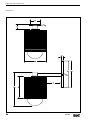
1
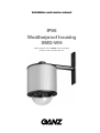
Installation and service manual
IP66
Weatherproof housing
SMD-WH
Please read this manual before storing, handling,
installing, mount or power the unit.
This installation and service manual (edition 01 - 10/2000) applies to weatherproof housing SMD-WH,
power supply unit SMD-WH-PS, mounts SMD-WH-CM and SMD-WH-WM,
and sunshield SMD-WH-SS (valid from 2000)
Contents
Introduction
Intended use
4
Electromagnetic compatibility
4
Final assembly
11
Identification plate
4
Installing the power supply unit
12
Preparing the connections
12
Safety instructions
Danger of electric shock
5
Connectors in the power supply unit
13
Installation and maintenance
5
Operation without protocol converter
14
Symbols used in this manual
5
Operation with protocol converter
15
Finishing off the installation
16
Product description
List of parts supplied
6
Operation and maintenance
Accessories
6
Trouble shooting
17
Function overview
6
Disassembly
18
Components
7
Replacing the fuse
18
Cleaning
19
Installation
Preparations
8
Proper disposal
19
Attaching the mount
9
Technical specifications
20
Dismantling the housing
9
Dimensions
22
Mounting the base plate
10
Operating the fan
10
Installing the camera
11
Introduction
Introduction
This installation and service manual is intended for
persons (electricians and service personnel) responsible for installing and maintaining the housing and the
dome camera system. These persons must be
acquainted with the electro-technics regulations and
follow them at all times. This manual is not suitable for
persons who lack proper specialist knowledge.
Intended use
The weatherproof housing SMD-WH is designed to
receive a dome camera system from the Computar
SMD series. It is intended for outdoor mounting and
protects the installed dome camera system from
water, dirt, moisture and damage. Other uses are not
permissible.
Please contact us if you have any questions about the
housing or camera that are not answered in this
manual.
CBC (Europe) Ltd.
7/8 Garrick Industrial Centre, Irving Way
NW9 6AQ London - GB
Phone +44 (0) 208 732 3310
Fax +44 (0) 208 202 3387
or
CBC (Deutschland) GmbH
Hansaallee 191
D – 40549 Düsseldorf
Phone +49 (0) 211 53 06 70
Fax +49 (0) 211 53 06 71 80
Electromagnetic compatibility
The weatherproof housing SMD-WH have been tested
and marked in compliance with European directive
89/336.
Identification plate
For the SMD-WH housing you will find the type
number on the box. For the SMD-WH-PS you will find
the identification number both on the box and on a
label on the main board. These numbers permit
precise identification. Make a note of them for quoting
when you have questions or want to order spare
parts.
4
SMD-WH
Safety instructions
Safety instructions
Danger of electric shock
Installation and maintenance
• Only install the camera, power supply unit and
ancillary devices to the correct mains supply.
• The installation procedure described in this manual
may only be performed by experienced and qualified personnel. The relevant electro-technical regulations are to be observed and met at all times.
• Only use the SMD-WH-PS power supply unit.
• Disconnect the power supply unit from the mains
and from all other devices in the event of a malfunction.
• Ensure that only qualified personnel (electricians)
are assigned to the installation and maintenance of
the device.
• Only store the devices in places that are free of
damp and are protected from the weather.
• If the safe operation of a device can no longer be
guaranteed, it must be stopped and secured
against accidental restart.
Safe operation is no longer possible if, for example:
- the device, power supply unit or cables bear
visible signs of damage
– the device, power supply unit or cables
no longer function properly
– the device has been penetrated by objects
or moisture
– the device was stored inappropriately for a long
time, or subjected to stress during transport.
If so, have CBC’s technical department check the
unit.
• During installation of the housing, follow the reference material that comes with those devices that
operate in conjunction with it, e.g. monitor screens
or control units. Here you will find important safety
instructions and information on approved uses of
the device.
• Carry out all the maintenance tasks described in
this manual. Performing work not described in the
manual could result in personal injury, or damage to
the device or material assets.
• Ensure that a safe foothold is available during work
under ceilings, up masts or in other high places.
Only use safety ladders. Use safety belts if necessary.
Symbols used in this manual
Safety instructions in this manual are twofold:
B
z
Danger of electric shock
Failure to observe safety instructions marked
with this symbol could result in electric
shock. This symbol denotes immediate
danger.
Warning
This symbol warns you of possible damage
to the device or other objects.
You will also be given tips that make operation easier.
(10/2000)
☞
SMD-WH
Note
This symbol denotes a special tip on how to
handle the device.
5
Product description
Product description
List of parts supplied
Function overview
1 Weatherproof housing SMD-WH with heater, fan
and quick-mounting plate, fully wired
The IP66 weatherproof housing SMD-WH and mounts
are made of high-quality, non-corroding aluminium.
The power-supply housing is composed of aluminium
and protected by a thick coat of paint.
1 Packet of silica gel
1 Installation and service manual
Accessories
1 Power supply unit SMD-WH-PS
1 Set of mounting components, consisting of:
4 Fixing brackets with screws
1 Seal for the cover of the power supply unit
1 Ceiling mount SMD-WH-CM
with prefabricated connecting cable
SMD-WH is specially designed for the quick and easy
installation of the SMD dome camera system. The
device comes completely prewired. The dome camera
system itself can be located on the quick-mounting
plate in a few simple steps.
The housing is fitted with a controlled heater and a
fan. The heater and fan switch on automatically at low
temperatures to guarantee top performance of the
camera at all times.
The two different mounts allow the housing to be fixed
to ceilings or walls and poles respectively. The entire
cable harness is routed within the mount and housing.
A rigid casing also protects it.
The optional sunshield offers additional cooling.
1 Wall mount SMD-WH-WM
with prefabricated connecting cable and stopper
1 Sunshield SMD-WH-SS
1 Computar SMD dome camera:
SMD 08P-II
SMD 12P-II
SMD 20P
SMD 16C
6
z
Warning
Owing to the dissipation effects of strong
winds and high humidity, the ambient temperature of the installation site can fall well
below the temperature measured in a
shielded place. Be sure to allow for this
possibility if the weatherproof housing is be
used in extreme conditions (e.g. on bridge
piers or high-rise buildings).
SMD-WH
Product description
Components
The system consists of the following parts:
Wall mount SMD-WH-WM
Ceiling mount SMD-WH-CM
Sunshield SMD-WH-SS
(10/2000)
Weatherproof housing SMD-WH
SMD-WH
Power supply unit SMD-WH-PS
7
Installation
Installation
Preparations
The device can be mounted in various ways depending on the customer’s requirements. The details of
each case cannot be given here. The following points
do however apply universally. Be sure to observe
them.
B
A
z
8
Danger of electric shock
Only use the power supply unit provided,
i.e. SMD-WH-PS.
Danger of falling
Ensure that a safe foothold is available during
installation work in high places. Only use
safety ladders. Use safety belts if necessary.
❚ Do not place the power supply unit next to radiators or other heat sources. Avoid locations that are
exposed to direct sunlight.
z Ensure that the load bearing force of ceilings, walls
and attached structures can safely support the
weight of the whole system. Also allow for movement and vibration of the camera.
❚ Install the power supply unit where it can be easily
accessed at all times.
❚ Ensure that enough space is available for laying the
cables.
❚ Ensure that the heat sink located on the outside
of the power supply can dissipate heat freely.
Warning
Choose the installation site so that the power
supply unit will not be exposed to extreme
temperatures.
The ambient temperature must lie between
-20 °C and +40 °C.
SMD-WH
Installation
Attaching the mount
Mount SMD-WH-CM is for attaching the housing to
solid ceilings. Mount SMD-WH-WM is for attaching
the device to walls.
• Using three screws, fix ceiling mount SMD-WH-CM
to a ceiling with adequate load bearing capacity,
or
alternatively, slide on the supplied end caps, and
fix wall mount SMD-WH-WM to a wall using two
screws.
• Use the appropriate fittings to ensure secure
mounting, e.g. wall plugs, underlay washers, split
washers, self-locking bolts and screws.
• Route the cable harness out of the mount either
towards the back or to the side.
• If necessary make an additional seal around the
cable harness where it passes through the mount
or other surfaces (e.g. brick-work) with a suitable
filler (e.g. silicon).
• Finally, check that the mount has been securely
fastened.
Dismantling the housing
• By way of preparation, place the housing on a level
surface from which it cannot roll off.
• Loosen the three Allen screws on the lower part of
the housing and separate the housing itself from
the base plate. This allows the lower part to be
separated of about 150 mm.
• Loosen the two red safety fastenings on the base
plate and unhook both safety rods.
z
Warning
The base plate is now completely detached
from the rest of the housing.
(10/2000)
• If the optional sunshield is being used, completely
unscrew the three Allen screws in the cover of the
sunshield and detach the upper disk from the
cylinder.
SMD-WH
9
Installation
Mounting the base plate
The base plate of the housing contains the heater
and fan as well as the quick-mounting plate for
installing the camera. The quick-mounting plate has
a free 3-pole connector for the data lines (RS485).
• Remove the nuts and split washers from the base
plate.
• If necessary, position the cover of the sunshield on
the base plate and align using the grub screw.
• Pass the mount wires through the opening in the
base plate, align the base plate (the grub screw
must be level with the borehole in the mount), and
position the base plate squarely on the mount.
Ensure that the packing rings are positioned correctly.
• Attach the split rings and nuts, and tighten them
uniformly. Ensure that the base plate – and the
sunshield if it is being used – does not tilt.
• Remove the plug from connector RS485. Insert
the three unattached cables from the mount into
the terminal screws of the plug as follows:
Green = DATA +
Orange = DATA –
White = GND
• Push the plug firmly onto connector RS485.
• Push the green plug firmly onto connector XP1 on
the heater circuit board.
• Connect the BNC plug to the BNC connector of the
quick-mounting plate.
Operating the fan
The ventilator on the heater circuit board can be
started automatically or manually. In automatic mode
the ventilator always switches on together with the
heater. In manual mode the ventilator runs continuously. You can select the operating mode using the
jumper on the heater circuit board.
• Push the jumper onto the two right-hand contacts
(position JB) to select automatic ventilator mode
(factory setting).
• Push the jumper onto the two left-hand contacts
(position JA) to make the ventilator run continuously. The ventilator will start as soon as power is
supplied the heater circuit board.
10
SMD-WH
Installation
Installing the camera
z
Warning
Before installation read the installation
manual that comes with the SMD camera.
• Lift the camera under the quick-mounting plate and
open the side flap in the camera housing.
• Push the 9-pole plug from the quick-mounting plate
firmly onto the connector in the camera housing. If
necessary, switch over the switch next to the connector and close the side flap again.
• Position the camera in the bore holes on the quickmounting plate using the three clamps, press down
slightly and turn clockwise until the clamps engage.
• Turn the safety lever on the camera housing and
secure on the quick-mounting plate with a screw.
Finally, check once again that the camera is securely fastened on the base plate.
Final assembly
• Tearing its plastic enclosure, place the supplied
silica gel packet on the quick-mounting plate and
fix it down (with scotch tape or cable ties).
• Lift the housing under the base plate and hook in
both safety rods.
• Secure the safety rods using the red fastenings.
• Carefully slide the housing onto the base plate. Be
careful not to squash or damage any cables. Ensure that the packing rings on the base plate are
positioned correctly.
• Tighten the three Allen screws on the dome uniformly.
• If the optional sunshield is being used, slide the
cylinder over the weatherproof housing and fasten it
to the cover using the three Allen screws.
(10/2000)
• Finally, check once again that the whole structure is
secure.
SMD-WH
11
Installation
Installing the power supply unit
The power supply unit comes with four fixing brackets
and screws. The clips can be attached to the bottom
of the power supply unit for external mounting on a
suitable surface.
• Arrange the clips as desired and secure them using
the self-tapping cross-recessed screws.
• Mount the power supply near the weatherproof
housing using a suitable screw in each of the four
fixing brackets.
• Use the appropriate fittings to ensure secure
mounting, e.g. wall plugs, underlay washers, split
washers, self-locking bolts and screws.
• Finally, check once again that all screws are secure.
Preparing the connections
B
z
Danger of electric shock
Do not connect the power supply unit to
the mains until all other cables have been
connected and checked.
Warning
Read the manuals that come with the SMD
camera, the control keypad and, if applicable, the Computar CS PCD-II protocol
converter. Here you will find important
information and safety instructions.
• Pass all cables through the cable entry gland in the
power supply housing.
• Then tighten the cable entry gland and seal any
unused openings using suitable filler (e.g. silicon).
12
SMD-WH
Installation
Connectors in the power supply unit
The power supply unit feeds the camera, heater and
fan and, if used, the protocol converter CS PCD-II.
1 Main fuse 500mA, 250 V
7 Connector for data lines to control keypad
2 Potentiometer for amplifying the video signal (not
applicable if CS PCD-II used)
8 Connector for camera data lines
3 Green LED (indicates unit is operational)
4 CS PCD-II power supply connector
5 Secondary fuse 2 A, 250V
9 Camera and heater power supply connector
10 Video input from camera
11 Video output
12 Mains connection 230 V ac
(10/2000)
6 Red LED indicates malfunctions (short circuit)
SMD-WH
13
Installation
Operation without protocol converter
The CS PCD-II protocol converter does not have to be
used if the Computar SCC-2 or SCC-3 control keypad
is connected.
The video signal from the camera is fed through the
amplifier. The gain can be varied from 0 to 12 dB. The
amplifier permits a maximum range of approx. 700 m.
z
Warning
Only use type RG59/U coaxial cable
(75 Ohms).
• Pass the weatherproof housing’s cable harness
through the large cable entry gland.
Data lines to controller
• Insert the data lines from weatherproof housing’s
cable harness into the XDO terminal screws as
follows:
Green = DATA +
Orange = DATA –
White = GND
Outgoing coaxial video cable
• Slide back the shielding on both coaxial cables up
to the opening in the housing. Cut the excess of
the shielding and fix it to the housing using the
earthing screws provided.
Cable harness from housing
• Pass the coaxial cable of the outgoing video cable
through the cable gland on the right of the large
one, insert the video cable in the VIDEO OUT binding post and check that it is properly secured.
Mains cable 230 V ac
• Insert the video cable in the VIDEO IN binding post
and check that it is secured.
• Pass the data lines for the control keypad through
one of the cable entry glands on the right and insert
into the DATA terminal. Observe the marking of the
terminals on the circuit board.
• Insert the camera and heater power supply cables
from the weatherproof housing’s cable harness into
the XP terminals as follows:
Blue = S1
Brown= S2
Black = –
Red = +
• Pass the mains cable through the cable entry
gland on the left and insert into the 230 V ac terminal. Observe the marking of the terminal on the
circuit board.
• Finally, check that all cables are secure and tighten
the cable entry glands.
14
SMD-WH
Installation
Operation with protocol converter
The CS PCD-II protocol converter must be installed
first if a Computar CS series control system is being
used.
z
Warning
Read the installation manual that comes with
the protocol converter. There you will find
important information and safety instructions.
• Remove the caps from the four corners of the
protocol converter and unscrew the screws.
• Position the four fixing blocks in the recesses and
secure using the four screws.
• On the power supply board, unscrew the four
screws on top of the spacers.
• Turn over the protocol converter, align it on the
spacers and secure it using the four screws.
• Pass the weatherproof housing’s cable harness
through the large cable entry gland.
• Connect a BNC plug to the video cable and mate
it to the “CAMERA” equivalently marked BNC
socket of the protocol converter. Be sure to connect the shielding in the BNC plug correctly.
• Pass the coaxial cable of the outgoing video cable
through one of the two right-hand cable entry
glands, connect a BNC plug to the video cable and
mate it to the “CONTROLLER” equivalently marked
BNC socket of the protocol converter.
• Insert the data lines from weatherproof housing’s
cable harness into the terminal screws of the protocol converter as follows:
Green = RS485 +
Orange = RS485 –
White = S
• Connect the XPCD binding posts to the CS PCD-II
24 V ac IN/OUT binding posts using two suitable
pieces of cable.
(10/2000)
• Insert the camera and heater power supply cables
from the weatherproof housing’s cable harness into
the XP terminal screws as follows:
Blue = S1
Brown= S2
Black = –
Red = +
SMD-WH
15
Installation
• Pass the mains cable through the cable entry
gland on the left and insert into the 230 V ac terminal. Observe the marking of the terminal on the
circuit board.
• Finally, check that all cables are secure and tighten
the cable entry glands.
Finishing off the installation
B
Danger of electric shock
After connection ensure that all cables
have been laid in such a way that they
cannot be kinked, squashed or otherwise
damaged.
After all connections have been made ensure that the
installation has been successful. Pay heed to the
LEDs on the circuit board of the power supply unit. If
necessary adjust the gain of the video signal (operation without protocol converter).
• Use a screw driver to adjust the gain of the video
signal if necessary. Using an oscilloscope, measure
the amplitude of the video signal at the end of the
RG59/U cable run (near the Monitor or the vision
device; rotate the trimmer to obtain a reading of 1V
peak to peak.
• Seal any unused cable entry glands with a suitable
filler (e.g. silicon).
• Screw down the green-yellow earth cable from the
power supply under the screw in the cover.
• Place the seal supplied for the purpose in the cover
recess. Ensure the seal has been laid evenly and is
not twisted.
• Put the cover of the housing in place and secure it
evenly using the four screws.
16
SMD-WH
Operation and maintenance
Operation and maintenance
Trouble shooting
The following table is to help you identify the causes of
malfunctions and help you rectify them.
Problem
Likely cause
Suggested remedy
Camera faults
Incorrect connections.
Check connections to wiring harness.
Poor connections.
Check connections in the housing and in
the power suplly unit.
Incorrect connections.
Check BNC connection in the housing.
No picture
Check connection of the coaxial cable in
the power supply unit.
No camera function
No power.
Check power supply unit and lines.
Condensation in the housing
Fan/heater assembly out of
function.
Check fan/heater unit and thermostat in
the housing.
(10/2000)
Check fan/heater power in the power
supply unit.
SMD-WH
17
Operation and maintenance
Disassembly
Replacing the fuse
Several tasks may require the disassembly of the
camera.
There are two safety fuses in the power supply unit.
These must be replaced by an expert if defective.
B
Danger of electric shock
First of all, disconnect the power supply unit
from the mains and from all other devices.
• Ensure that the camera has been switched off.
• If the optional sunshield is being used, completely
unscrew the three Allen screws in the cover of the
sunshield and detach the cover from the cylinder.
• Loosen the 3 Allen screws in the dome of the
weatherproof housing and slowly pull the housing
down away from the base plate until the safety rods
hold it.
• Hold the housing firmly, loosen the two red safety
fastenings on the base plate and unhook both
safety rods. The housing is now completely detached from the base plate.
• Open the side flap in the camera housing and pull
out the 9-pole plug from the connector in the camera housing.
B
Danger of electric shock
Firstly, disconnect all devices from the mains.
z
Warning
Before fitting a new fuse check what might
have caused the fault. Only use a new fuse
with the following ratings.
Primary fuse: 250 V, 500 mA,
Secondary fuse: 250 V, 2 A.
• Open the housing of the power supply unit.
• Remove the safety cover and take out the fuse from
the holder.
• Insert the new fuse and replace the cover.
• Replace the cover of the housing and secure with
the four screws, ensuring an even fit. Make sure
that the seal has been evenly laid and that it is not
twisted.
• Unscrew the screws on the safety lever and turn
the safety lever on the camera housing.
• Turn the camera anticlockwise and detach the
quick-mounting plate from the 3 clamps of the
quick-mounting plate.
18
SMD-WH
Operation and maintenance
Cleaning
Proper disposal
B
The housing and other system components (power
supply unit, cables, camera) contain substances that
could damage the environment. These must be
disposed of professionally. Devices that are no longer
required are to be disposed of by a professional
reprocessing service or taken to a local waste reprocessing plant.
z
Danger of electric shock
Ensure that no fluids pass into the interior of
the power supply unit during cleaning.
Warning
Never use alcohol, thinners or an abrasive or
corrosive cleaning agent to clean the device.
These could damage plastic components or
damage the paintwork. Only use water and a
mild household cleaning agent in small
quantities.
Ensure that a safe foothold is available. Only
use safety ladders.
Do not clean the mechanism itself. Do not
clean any part of the camera.
(10/2000)
Only clean the outside of the dome, using a
soft cloth to do so.
SMD-WH
19
Operation and maintenance
Technical specifications
Power supply unit SMD-WH-PS
Material
Aluminium
Protection class
IP66
Video amplifier
0 ... 12 dB
Operating voltage
230 V ac, 50 Hz
Secondary camera voltage
12 V dc
Secondary voltage for heater/fan
18 V ac, 50 Hz
Dimensions (w × h × d)
254 × 219 × 102 mm
Weight
approx. 3.6 kg
Weatherproof housing SMD-WH
Material
Anti-corodal aluminium
Protection class
IP66
Current consumption of heater
9W
Fan switching
automatic/manual (continuous operation)
Operating conditions
Temperature: –20 ... +40 °C
Rel. humidity: 90% not condensing
Storage conditions
Temperature: –20 ... +60 °C
For storage periods of longer than one month
protect housing from damp by storing in a
sealed container
Dimensions (h × Ø)
268 × 200 mm
Weight
approx. 3.1 kg
Sunshield SMD-WH-SS
Material
Aluminium
Dimensions (h × Ø)
205 × 250 mm
Weight
approx. 0.6 kg
20
SMD-WH
Operation and maintenance
Ceiling mount SMD-WH-CM
Material
Anti-corodal aluminium
Cable harness
1 × mini-coaxial cable, 3 × data lines, 4 × power cables
Length approx. 2.5 m
Dimensions (w × h × d)
100 × 60 × 100 mm
Weight
approx. 0.64 kg
(10/2000)
Wall mount SMD-WH-WM
Material
Anti-corodal aluminium
Cable harness
1 × mini-coaxial cable, 3 × data lines, 4 × power cables
Length approx. 2.5 m
Dimensions (w × h × d)
80 × 260 × 290 mm
Weight
approx. 0.94 kg
SMD-WH
21
Operation and maintenance
Dimensions
22
SMD-WH
(10/2000)
Operation and maintenance
SMD-WH
23
CBC (Deutschland) GmbH
CBC (Poland) Sp.z o.o.
Hansaallee 191
D – 40549 Düsseldorf
T: +49 (0) 211 53 06 70
F: +49 (0) 211 53 06 71 80
Ul. G. Morcinka 5, Paw 6
01496 Warszawa - PL
T: +48 (0) 22 638 4440
F: +48 (0) 22 638 4541
CBC (Europe) Ltd.
CBC (Europe) Ltd. Paris Branch
7/8 Garrick Industrial Centre, Irving Way
London NW9 6AQ - GB
T: +44 (0) 208 732 3312
F: +44 (0) 208 202 3387
1, Avenue des Marguerites
ZAC des Petits Carreaux
94389 Bonneuil sur Marne Cedex - France
T: +33 (0) 1 43 99 04 24
F: +33 (0) 1 43 99 59 06
CBC (Europe) Ltd.
Ufficio di Milano
Via Carolina Romani, 1/11
20091 Bresso (MI) - Italy
T: +39 02 6650 3210
F: +39 02 6650 3204