1
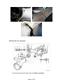
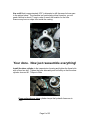
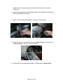
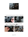
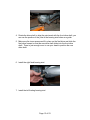
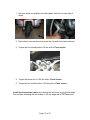
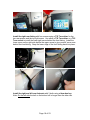
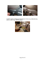
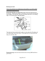
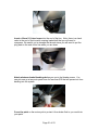
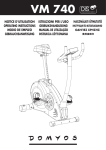
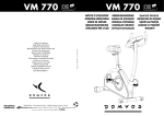
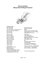
Slave Cylinder
Weep Hole Drilling Procedure
Tools Required:
T20 Torx Driver
T25 Torx Driver
T25 Torx Bit with ¼ Ratchet Wrench
4mm Hex Key (Allen wrench)
5mm Hex Key
6mm Hex Key
8mm Hex Key
12mm Hex Key
4mm Hex Socket
5mm Hex Socket
8mm Hex Socket
12mm Hex Socket
14mm Wrench
16mm Wrench
14mm Socket
15mm Socket
16mm Socket
17mm Socket
Modified 30mm Socket
Flat Screwdriver
Phillips Screwdriver
Torque Wrench with Max 200Nm
Torque Wrench with Min 7Nm
½” Breaker Bar with 4ft. Pipe
Ratchet Extensions
Needle Nose Pliers
Mallet
Piece of wood to seat drive shaft.
Straight edge (drive shaft phasing)
Disposable gloves, rags
Floor Jack
Paint Marker Pen
10mm x 1 Bleed Screw
Brake Bleeding Device or a helper.
DOT4 Brake Fluid
5/32” drill bit 6” long
Drill
Small pick for removing burr.
Small flashlight
A couple of large cable ties.
Paper Gasket – 23122352156
*Seals for clutch line - 21522332604
*Slave Cylinder – 21522333433
Spline Lubricant - 99990000601
*Only if replacing cylinder.
Page 1 of 23
Remove rear license plate carrier with T25 Torx driver.
Remove rear wheel and spacer using 17mm socket wrench (5 bolts).
Tilt the wheel to simplify the removal.
Remove rear brake caliper using an 8mm hex key to remove the two bolts
(1,3). (NOTE: These bolts are different from each other, keep track of which one
goes where for reassembly.)
Page 2 of 23
Remove the rear wheel speed sensor with a 4mm hex key. (This only applies
to the older bikes, prior to 2002. The newer bikes don’t have this sensor.)
Remove the brake line from the two retaining clips (two arrows in image above.)
Hang the rear caliper from the frame with cable ties.
Remove the rear drive
Page 3 of 23
1. Loosen the reaction link(3) with a 16mm wrench and 16mm socket.
2. Release the clamping strap(5) on the flexible boot with a flat screwdriver.
3. Loosen locknut(7) with a 30mm socket and then the floating bearing
stud(6) with a 12mm hex key on left side (high release torque).
4. Loosen fixed bearing stud(4) on right side with a 12mm hex key.
5. Remove the locknut, floating bearing stud, fixed bearing stud and bolt on
reaction link.
6. Slide rear drive out. (Keep upright so no oil will spill).
7. Make sure that the inner races for the bearings do not fall out and
become lost or damaged.
Remove the left rear footrest with a 6mm hex key (3 bolts)
Page 4 of 23
Remove the left front footrest with a 6mm hex key (3 bolts) and a T25 Torx
driver (2 screws).
Remove the right rear footrest with a 6mm hex key (3 bolts)
Remove the right front footrest with a 6mm hex key (3 bolts) and a T25 Torx
driver (2 screws).
Remove the right rear fairing section with a T25 Torx driver. There are 4
screws.
1. Open the front seat by pulling the lever inside the left side case and you
will be able to remove the top-right screw.
2. Open the left case and remove the upper and lower rear screws.
3. The fourth screw is hidden under the front fairing. Grab the front fairing
near the bottom padded edge and pop it out. If you pull up on the fairing
you will be able to see and remove the last screw in the rear fairing. It is a
T25 Torx screw so you can either use a T25 bit on a small ratchet wrench
or a T20 Torx driver will get in the screw at an angle. I found it easiest to
loosen the screw and then use my fingers to unscrew it the rest of the
way.
Page 5 of 23
Remove the rear swing arm.
1. Remove the circlips (9) with a pair of needle nose pliers.
Page 6 of 23
2. Remove the right threaded ring(8) with a 30mm socket. (High release
torque, many have needed to use a 4ft. pipe on a breaker bar to release
this. There may be a loud bang when it finally releases. Use caution
though, the factory does not use loctite but if someone anyone including a
dealer has disassembled the swing arm they may have incorrectly used
loctite on these nuts. If they have you will need to heat the joint to about
300°F to soften the loctite and not damage the thre ads. If you do damage
the threads you will need a 24mm x 1.25 tap to clean them up. It is a
strange size and you may have trouble finding one.)
3. Remove the left lock ring(2) with a 30mm socket.
4. Remove the left threaded ring(3) with a 12mm hex key.
5. Loosen but do not remove the left(4) and right(7) bearing studs with a
14mm socket.
6. Remove the lower bolt(5,6) on the rear shock and secure the shock up out
of the way to the frame. The bolt requires a 14mm wrench and the nut
requires a 15mm socket.
7. Remove the left and right bearing studs.
8. You will need to disconnect the drive shaft in order to twist the swing arm
enough to remove it.
9. Slide the rubber boot back off the transmission flange.
10. Disconnect the drive shaft by placing a screwdriver inside the u-joint and
against the end of the transmission shaft. Pry the drive shaft off the
transmission shaft. It is held in place by a circlip that is inside the drive
shaft, you can not see the circlip. The drive shaft should pop right off.
11. Remove the swing arm and drive shaft assembly by twisting the rear of
the swing arm towards the left and sliding the whole assembly backwards.
Remove the slave cylinder with a 5mm hex key. The three screws need to be
removed simultaneously. Loosen each screw alternately and uniformly.
Pull the slave cylinder away from the transmission and secure it up and out of the
way.
If you are replacing the slave cylinder disconnect the clutch hydraulic lines.
If you are not replacing the slave cylinder leave the clutch lines connected.
1. Place a catch basin under the lines to catch any clutch fluid that will
drain out.
2. Remove the two banjo bolts with a 4mm hex key.
3. Discard the old seals.
4. Screw the banjo bolts into your new slave cylinder with new seals
above and below the banjo bolts.
5. The service manual recommends installing a new paper gasket but I’m
not sure what the point would be since we are drilling a hole into this
cavity anyway.
6. Do not tighten the banjo bolts too much since you will need to allow
them to rotate to position the lines when you bolt the slave cylinder into
the housing.
Page 7 of 23
Use a drill that is approximately 5/32” in diameter to drill the weep hole as seen
in the picture below. The diameter isn’t particularly critical, however, you will
need a bit that is about 6” long in order to reach the location for the hole.
Remove any burrs or chips from inside the casting.
Your done. Now just reassemble everything!
Install the slave cylinder in the transmission housing and tighten the three bolts
with a 5mm hex key. Tighten the bolts alternately and uniformly so that the slave
cylinder does not tilt. Torque to 9Nm
If you replaced your slave cylinder torque the hydraulic lines now to
7Nm.
Page 8 of 23
Drive shaft phasing
Before you reassemble the swing arm take the front half of the drive shaft
and assembly it with the rear half so that the drive shaft is in phase. The
picture below depicts what this means. The service manual doesn’t
indicate the need to phase the drive shaft but it is a good idea for any
drive shaft with two u-joints. Mark the drive shaft with a paint marker so
you will be able to align the shaft when you install the rear drive. I found
that if I marked the shaft directly inline with the yoke that I could then align
the front drive shaft so the paint mark was at 3 o’clock and then I could
align the bearing stud holes with the yoke on the rear drive and thereby
align the front and rear drive shafts.
Install the Drive Shaft and Swing Arm
1. Apply spline lubricant to the transmission spline. BMW GL261 (I used
the Honda Moly 60 which has very good reviews for this application and is
available at any Honda dealer. The Moly 60 is 60% molybdenum
Disulfide. You can not use regular Moly grease from the auto store.)
2. If the rubber boot came off the front of the swing arm during disassembly
you will need to remove the circlip from inside the swing arm housing, put
the rubber boot in place and install the circlip inside the rubber boot. This
will hold the boot securely in place.
3. Slide the swing arm and drive shaft assembly back into position while
rotating the back end slightly to the left to clear the stud on the left side of
the bike below the battery tray.
4. Slide the drive shaft on to the transmission spline and seat the circlip by
hitting the end of the drive shaft with a mallet. This can be a little
frustrating because you can barely reach into the drive shaft to align it. It
may help to have someone apply a little pressure on the end of the drive
shaft from the rear of the swing arm. Use a piece of wood or other non-
Page 9 of 23
metallic object to reach the end of the drive shaft from the rear of the
swing arm.
5. Apply a little grease around the sealing edge of the rubber boot and slide it
over the transmission housing.
6. Screw in left and right bearing studs until they are finger tight.
7. Attach the shock to the swing arm using a 14mm wrench on the bolt and
a 15mm socket on the nut. Torque to 50Nm.
8. Torque the left and right bearing studs to 160Nm with a 14mm socket.
Page 10 of 23
9. Install the right threaded ring and torque to 200Nm with a 30mm socket.
10. Install the left threaded ring and torque to 10Nm with a 12mm Hex
Socket. **********Note the low torque value.**********
Page 11 of 23
11. Install the left lock nut with a modified 30mm socket and torque to
160Nm while holding the left threaded ring stationary with a 12mm hex
key.
12. Install the left and right circlips with needle nose pliers with the hooks
toward the outside.
Install the Rear Drive
1. Look inside the swing arm and rotate the paint mark on the drive shaft so
that it is at 3 o’clock.
2. Coat the splines of the rear drive shaft with lubricant (BMW GL261).
3. If available, place the rear drive on a floor jack and slide into position.
Page 12 of 23
4. Rotate the drive shaft to align the paint mark with the front drive shaft, you
can use the position of the yoke in the bearing stud holes as a guide.
5. Make sure the inner races are still in place on the final drive and slide the
final drive forward so that the rear drive shaft slides into the front drive
shaft. There is just enough room to use your hand to position the rear
drive shaft.
6. Install the right fixed bearing stud.
7. Install the left floating bearing stud.
Page 13 of 23
8. Install the reaction link bolt.
9. Torque the right bearing stud with a 12mm hex socket to 160Nm.
10. Torque the left bearing stud with a 12mm hex socket to 7Nm.
11. Install left locknut and torque with a modified 30mm socket to 160Nm
while holding the left bearing stud stationary with a 12mm hex key.
Page 14 of 23
12. Torque the reaction link with a 16mm wrench and 16mm socket to
43Nm.
13. Slide rubber boot over swing arm and tighten clamp.
Install Rear Brake Caliper
Page 15 of 23
1. Install the rear brake caliper using an 8mm hex socket and torque to
40Nm. (Note: The rear bolt has a shoulder and the forward bolt has a
loose washer.)
2. Install the rear wheel speed sensor with a 4mm hex socket and torque to
5Nm.
3. Insert the brake line onto the two retaining clips.
Install the Rear Wheel.
Page 16 of 23
1. Roll rear wheel into position and slide spacer over hub on right side of
wheel.
2. Place wheel onto rear drive and screw the five bolts into place uniformly.
3. Torque the four outside bolts to 50 Nm with a 17mm socket.
4. Torque the center bolt to 105 Nm with a 17mm Socket.
5. Torque the four outside bolts to 105 Nm with a 17mm socket.
Install the license plate carrier by inserting the two hooks on the bottom edge
first and then attaching the two screws on the top edge with a T25 Torx driver.
Page 17 of 23
Install the right rear fairing with four screws using a T25 Torx driver for the
two rear screws and the top right screw. Use either a T20 Torx driver or a T25
Torx socket to install the lower right screw behind the front fairing. Install the
lower screw on the right side before the upper screw to give yourself more room
behind the front fairing. Snap the lower edge of the front fairing back into place.
Install the right and left rear footrests with 3 bolts using a 6mm hex key.
Note: On the left side the bolt on the bottom left is longer than the other two.
Page 18 of 23
Install the right and left forward footrests with 3 bolts using a 6mm hex key
and two screws using a T25 Torx driver.
Page 19 of 23
Bleeding the clutch.
This is only necessary if you replaced your slave cylinder. If you didn’t replace
the slave cylinder you are done!
Remove the right tip-over wing covers (known and the skirt and skirt trim in
the manual). There are two screws on the bottom of the trim piece and there are
three screws on the skirt itself. Two are on the bottom and one is on the trailing
edge. All 5 screws require a T25 Torx driver.
The clutch vent line is attached with a cable tie to the underside of the frame rail
at the back edge of the tip-over wing. Cut the cable tie so you can pull the line
away from the bike a little.
Remove the plug in the end of the line with a 5mm hex key. (BMW calls this a
grub screw)
Page 20 of 23
Insert a 10mm X 1 bleed screw into the end of the line. Note: there is a check
valve in the end of the line with a spring loaded ball that you will need to
compress. Be careful not to damage the threads since you will need to put the
plug back in the end of this line when you are done.
Attach whatever brake bleeding device you use to the bleeder screw. You
can pick one up at any auto parts store for less than $10 that will prevent air from
backing into the system.
Cover the paint on the motorcycle to protect it from brake fluid or you could ruin
your paint.
Page 21 of 23
Turn your handlbars to full right lock and shim a small piece of wood under
the front wheel to level the clutch reservoir.
Open the clutch reservoir on the handle bars by removing the four screws with
a Phillips screwdriver.
Fill the reservoir and slowly pump the clutch fluid through the system until all
air has been purged. Make sure that your bleed screw is not fully seated or you
will prevent the flow of fluid through the system.
When all the air has been removed, take the bleed screw out of the line and
reinstall the plug (grub screw) with a 5mm hex key.
Top off the clutch reservoir and reinstall the cover ensuring that the diaphragm
has been pushed back into the folded position. Tighten with a Philips head
screw driver.
Page 22 of 23
Fasten the clutch vent line back under the frame with a cable tie.
Reinstall the tip-over wing cover and trim.
You are now ready to ride!
Page 23 of 23