1
Service Manual
PTAC - PD Series (Electronic Controls)
Packaged Terminal Air Conditioners
Packaged Terminal Heat Pumps
PD-ServMan (04-09)
TECHNICAL SUPPORT
CONTACT INFORMATION
FRIEDRICH AIR CONDITIONING CO.
Post Office Box 1540 · San Antonio, Texas 78295-1540
4200 N. Pan Am Expressway · San Antonio, Texas 78218-5212
(210) 357-4400 · FAX (210) 357-4490
www.friedrich.com
Printed in the U.S.A.
Table of Contents
Important Safety Information ..........................................2-4
Capillary Tube Systems/Check Valve ............................28
Introduction ........................................................................4
Reversing Valve — Description/Operation ....................29
Typical Unit Components ...................................................4
Testing Coil ....................................................................30
Unit Identification ................................................................5
Checking Reversing Valves ...........................................30
Unit Specifications ..............................................................6
Reversing Valve
Touch Testing Heating/Cooling Cycle ...........................31
2009 Models Chassis Specifications/Performance .........7-8
2008 Models Chassis Specifications/Performance .......9-10
Electrical Rating Tables ....................................................11
Power Cord .......................................................................12
Remote Wall Thermostat / Low Voltage
Wire Connections .............................................................13
Procedure For Changing Reversing Valve ....................31
Compressor Checks ......................................................32
Locked Rotor Voltage Test ............................................32
Single Phase Connections ...........................................32
Determine Locked Rotor Voltage .................................32
Digital Control Features ...............................................14-15
Locked Rotor Amperage Test ........................................32
Digital Control Operation ..................................................16
Single Phase Running & Locked Rotor Amperage .......32
Digital Control User Input Configuration ...........................17
External Overload .........................................................32
Optional Hand Held Remote Control Operation ...............18
Checking the External Overload ...................................32
Digital Control Diagnostics & Test Mode .....................18-20
Compressor Single Phase Resistance Test ..................33
Components Testing ....................................................21-22
Compressor Replacement .......................................34-35
Refrigeration System Sequence of Operation ..................23
Routine Maintenance ...............................................36-37
Sealed Refrigeration System Repairs ...............................24
Refrigerant Charging .........................................................24
Method Of Charging ..........................................................25
Undercharged Refrigerant Systems ..................................26
Overcharged Refrigerant Systems ....................................26
Restricted Refrigerant Systems ........................................27
Troubleshooting Charts ....................................................38-39
Wiring Diagram Index .......................................................40-43
Wiring Diagrams for Electronic Control Board .................44-55
Wiring Diagrams for Wall Mounted Thermostats ..............56-58
Thermistors Resistance Values ........................................59-60
Warranty ........................................................................61
1
IMPORTANT SAFETY INFORMATION
The information contained in this manual is intended for use by a qualified service technician who is familiar
with the safety procedures required for installation and repair, and who is equipped with the proper tools and
test instruments required to service this product.
Installation or repairs made by unqualified persons can result in subjecting the unqualified person making
such repairs as well as the persons being served by the equipment to hazards resulting in injury or electrical
shock which can be serious or even fatal.
Safety warnings have been placed throughout this manual to alert you to potential hazards that may be
encountered. If you install or perform service on equipment, it is your responsibility to read and obey these
warnings to guard against any bodily injury or property damage which may result to you or others.
Your safety and the safety of others are very important.
We have provided many important safety messages in this manual and on your appliance. Always read
and obey all safety messages.
This is a safety Alert symbol.
This symbol alerts you to potential hazards that can kill or hurt you and others.
All safety messages will follow the safety alert symbol with the word “WARNING”
or “CAUTION”. These words mean:
WARNING
You can be killed or seriously injured if you do not follow instructions.
CAUTION
You can receive minor or moderate injury if you do not follow instructions.
All safety messages will tell you what the potential hazard is, tell you how to reduce the chance of injury,
and tell you what will happen if the instructions are not followed.
NOTICE
A message to alert you of potential property damage will have the
word “NOTICE”. Potential property damage can occur if instructions
are not followed.
PERSONAL INJURY OR DEATH HAZARDS
ELECTRICAL HAZARDS:
2
•
Unplug and/or disconnect all electrical power to the unit before performing inspections,
maintenance, or service.
•
Make sure to follow proper lockout/tag out procedures.
•
Always work in the company of a qualified assistant if possible.
•
Capacitors, even when disconnected from the electrical power source, retain an electrical charge
potential capable of causing electric shock or electrocution.
•
Handle, discharge, and test capacitors according to safe, established, standards, and approved
procedures.
•
Extreme care, proper judgment, and safety procedures must be exercised if it becomes necessary
to test or troubleshoot equipment with the power on to the unit.
•
Do not spray or pour water on the return air grille, discharge air grille, evaporator coil, control panel,
and sleeve on the room side of the air conditioning unit while cleaning.
•
Electrical component malfunction caused by water could result in electric shock or other electrically
unsafe conditions when the power is restored and the unit is turned on, even after the exterior is dry.
•
Never operate the A/C unit with wet hands.
•
Use air conditioner on a single dedicated circuit within the specified amperage rating.
•
Use on a properly grounded outlet only.
•
Do not remove ground prong of plug.
•
Do not cut or modify the power supply cord.
•
Do not use extension cords with the unit.
•
Follow all safety precautions and use proper and adequate protective safety aids such as: gloves,
goggles, clothing, adequately insulated tools, and testing equipment etc.
•
Failure to follow proper safety procedures and/or these warnings can result in serious injury or death.
REFRIGERATION SYSTEM HAZARDS:
•
Use approved standard refrigerant recovering procedures and equipment to relieve pressure before
opening system for repair.
•
Do not allow liquid refrigerant to contact skin. Direct contact with liquid refrigerant can result in minor
to moderate injury.
•
Be extremely careful when using an oxy-acetylene torch. Direct contact with the torch’s flame or hot
surfaces can cause serious burns.
•
Make sure to protect personal and surrounding property with fire proof materials.
•
Have a fire extinguisher at hand while using a torch.
•
Provide adequate ventilation to vent off toxic fumes, and work with a qualified assistant whenever
possible.
•
Always use a pressure regulator when using dry nitrogen to test the sealed refrigeration system for
leaks, flushing etc.
•
Make sure to follow all safety precautions and to use proper protective safety aids such as: gloves,
safety glasses, clothing etc.
•
Failure to follow proper safety procedures and/or these warnings can result in serious injury or death.
MECHANICAL HAZARDS:
•
Extreme care, proper judgment and all safety procedures must be followed when testing,
troubleshooting, handling, or working around unit with moving and/or rotating parts.
•
Be careful when, handling and working around exposed edges and corners of sleeve, chassis, and
other unit components especially the sharp fins of the indoor and outdoor coils.
•
Use proper and adequate protective aids such as: gloves, clothing, safety glasses etc.
•
Failure to follow proper safety procedures and/or these warnings can result in serious injury or death.
3
PROPERTY DAMAGE HAZARDS
FIRE DAMAGE HAZARDS:
•
Read the Installation/Operation Manual for this air conditioning unit prior to operating.
•
Use air conditioner on a single dedicated circuit within the specified amperage rating.
•
Connect to a properly grounded outlet only.
•
Do not remove ground prong of plug.
•
Do not cut or modify the power supply cord.
•
Do not use extension cords with the unit.
•
Failure to follow these instructions can result in fire and minor to serious property damage.
WATER DAMAGE HAZARDS:
•
Improper installation maintenance, or servicing of the air conditioner unit, or not following the above
Safety Warnings can result in water damage to personal items or property.
•
Insure that the unit has a sufficient pitch to the outside to allow water to drain from the unit.
•
Do not drill holes in the bottom of the drain pan or the underside of the unit.
•
Failure to follow these instructions can result in result in damage to the unit and/or minor to serious
property damage.
INTRODUCTION
This service manual is designed to be used in conjunction with the installation manuals provided with each unit.
This service manual was written to assist the professional HVAC service technician to quickly and accurately
diagnose and repair any malfunctions of this product.
This manual, therefore, will deal with all subjects in a general nature. (i.e. All text will pertain to all models).
IMPORTANT: It will be necessary for you to accurately identify the unit you are
servicing, so you can be certain of a proper diagnosis and repair.
(See Unit Identification.)
Typical Unit Components
Discharge Air Grille
Blower Wheel
Indoor Blower Housing
Gasket
Control Door
Filters
Condenser Fan Blade
Outdoor Grille
Condenser
Shroud
Condenser
Coil
Return Air Grille
Front Cover
4
Compressor
Evaporator Coil
Control Panel
Gasket
Basepan
Wall Sleeve
UNIT IDENTIFICATION
Model Number Code
PD H 07 K 3
S B
A
Series
PD = P Series Digital PTAC
Engineering Digit
Design Series
System
E = Cooling with or
without electric heat
Options
H = Heat Pump with
Auxiliary Heat
S = Standard
Nominal Cooling Capacity
07 = 7000 BTUh
09 = 9000 BTUh
12 = 12000 BTUh
15 = 15000 BTUh
Nominal Heater Size
(@ 230V or 265V)
0 = No Heater
2 = 2.5KW
3 = 3.4KW
5 = 5.0KW
Voltage
K = 208/230V - 1Ph. - 60Hz.
R = 265V - 1Ph. - 60Hz.
PTAC Serial Number Identification Guide
Serial Number
Decade Manufactured
L=0
C=3 F=6 A=1
D=4 G=7
B=2
E=5
H=8
Year Manufactured
A=1
D=4 G=7 B=2
E=5
H=8
C=3
F=6 J=9
L
J
A
M
00000
Production Run Number
J=9
PRODUCT LINE
P = PTAC
K=0
M = PTAC
Month Manufactured
A=Jan D=Apr G=Jul K=Oct
B=Feb E=May H=Aug L=Nov
C=Mar F=Jun J=Sep M=Dec
5
Electric Heat Data / Model / Identification / Components / Dimensions
For 2009 and 2008 Models
Electric Heat Data, PDE/PDH 07/09K/R
PDE/PDH07K
HEATER WATTS
2500/2050
VOLTAGE
3400/2780
PDE/PDH07R
2500
230/208
3400
265
PDE09K0
PDE/PDH09K
0 Kw
2500/2050 3400/2780
230/208
230/208
PDE/PDH09R
2500
3400
265
HEATING BTUh
8500/7000
11600/9500
8500
11600
0
8500/7000 11600/9500
8500
11600
HEATING CURRENT (AMPS)
11.4/10.4
15.3/13.9
9.8
13.2
0
11.4/10.4
15.3/13.9
9.8
13.2
MINIMUM CIRCUIT AMPACITY
14.1
19.0
12.2
16.4
6.0
14.1
19
12.2
16.4
15
20
15
20
15
15
20
15
20
5000/4090
2500
BRANCH CIRCUIT FUSE (AMPS)
Electric Heat Data, PDE/PDH 07/09K/R
PDE12K0
HEATER WATTS
VOLTAGE
0 Kw
PDE/PDH12K
2500/2050
230/208
3400/2780
PDE/PDH12R
230/208
HEATING BTUh
0
8500/7000
HEATING CURRENT (AMPS)
0
11.4/10.4
15.3/13.9
MINIMUM CIRCUIT AMPACITY
7.6
14.1
19
BRANCH CIRCUIT FUSE (AMPS)
15
15
20
3400
PDE15K0
5000
265
11600/9500 17000/13900 8500
0 Kw
PDE/PDH15K
3400/2780
PDE/PDH15R
5000/4090
230/208
230/208
11600/9500 7000/13900
3400
5000
265
11600
17000
0
11600
17000
9.8
13.2
19.5
0
15.3/13.9
22.3/20.3
13.2
19.5
27.8
12.2
16.4
24.2
8.5
19
27.8
16.4
24.2
30
15
20
30
15
20
30
20
30
22.3/20.3
Typical Unit Components and Dimensions
Wall Sleeve
Outdoor Louver
Filters
Chassis
Return Air Grille
Front Cover
PDXWS Wall Sleeve Dimensions:
16” H x 42” W x 13 3 4 ” D
Front Cover Dimensions:
16” H x 42” W x 7 1 2 ” D
Cut-Out Dimensions:
16 1 4” x 42 1 4 ”
6
CHASSIS SPECIFICATIONS FOR 2009 MODELS
PDE Series Chassis Specifications
PERFORMANCE
PDE07K
PDE07R
Cooling BTUh
7500/7300
7500
9200/9000
9200
12200/12000
Power (Watts)
615/598
615
814/796
814
1140/1121
12.2
12.2
11.3
11.3
2.1
2.1
2.7
0.76
0.76
0.75
265
230/208
265
230/208
253-198
292-239
253-198
EER
Dehumidification
Sensible Heat Ratio
ELECTRICAL
PDE09R
PDE12K
PDE12R
PDE15K
PDE15R
12200
15000/14800
15000
1140
78
1579
10.7
10.7
9.5
9.5
2.7
3.8
3.8
5.5
5.5
0.75
0.72
0.72
0.72
0.72
D ATA
Voltage (1 Phase, 60 Hz)
230/208
Volt Range
253-198
292-239
Current (Amps)
2.9
2.7
Power Factor
0.9
0.9
Amps L.R.
18
Amps F.L.
Horsepower
AIRFLOW
PDE09K
D ATA
3.7
265
292-239
230/208
253-198
265
292-239
3.5
5.1
4.7
6.8
6.8
0.9
0.9
0.9
0.9
0.9
0.9
15
22.2
18.8
26.3
28
38
33
2.9
2.75
3.4
3.1
4.8
4.2
6.6
6.6
1/15
1/15
1/15
1/15
1/10
1/10
1/10
1/10
D ATA
Indoor CFM, High
250
250
250
250
325
325
350
350
Indoor CFM, Low
200
200
200
200
260
260
280
280
70
70
Vent CFM
PHYSICAL
60
60
60
60
70
70
D ATA
Dimensions
16 X 42 X13.5 16 X 42 X13.5
16 X 42 X13.5
16 X 42 X13.5 16 X 42 X13.5 16 X 42 X13.5 16 X 42 X13.5 16 X 42 X13.5
Net Weight
105
105
112
112
120
120
125
125
Shipping Weight
123
123
130
130
138
138
143
143
R-22 Charge
31
31
30
30
34
34
34
34
PDH07K
PDH07R
PDH09K
PDH09R
PDH12R
PDH15K
PDH15R
7200/7000
7200
9100/8900
9100
12000/11800
12000
14700/14500
14700
595/579
595
805/788
805
1165/1146
1165
1581/1559
1581
12.1
11.3
11.3
6400/6200
6400
8100/7900
8100
10400/10600
568/550
568
791/772
791
1035/1016
PDH Series Chassis Specifications
PERFORMANCE
Cooling BTUh
Power (Watts) Cool
EER
12.1
Heat Pump BTUh
Power (Watts) Heat
10.3
9.3
9.3
10600
13300/13100
13300
1035
1344/1324
1344
3.3
3.3
3.0
3.0
3.0
3.0
2.9
2.9
Dehumidification
2.1
2.1
2.7
2.7
3.8
3.8
5.5
5.5
0.76
0.76
0.75
0.75
0.72
0.72
0.72
0.72
265
230/208
265
230/208
253-198
292-239
253-198
D ATA
Voltage (1 Phase, 60 Hz)
230/208
Volt Range
253-198
292-239
265
292-239
230/208
253-198
265
292-239
Current (Amps)
3.0
2.7
3.9
3.4
5.1
4.8
6.8
6
Heat Pump Amps
2.6
2.4
3.3
2.9
4.5
4.4
5.8
5.3
Power Factor
0.9
0.9
0.9
0.9
0.9
0.9
0.9
0.9
Amps L.R.
18
14.8
22.2
18.8
26.3
28
38
32
Amps F.L.
2.9
2.75
3.4
3.1
4.8
4.2
6.6
5.4
1/15
1/15
1/15
1/15
1/10
1/10
1/10
1/10
Horsepower
AIRFLOW
10.3
COP
Sensible Heat Ratio
ELECTRICAL
PDH12K
D ATA
D ATA
Indoor CFM, High
250
250
250
250
325
325
350
350
Indoor CFM, Low
200
200
200
200
260
260
280
280
70
70
Vent CFM
PHYSICAL
60
60
60
60
70
70
D ATA
Dimensions
16 X 42 X13.5 16 X 42 X13.5
16 X 42 X13.5
16 X 42 X13.5 16 X 42 X13.5 16 X 42 X13.5 16 X 42 X13.5 16 X 42 X13.5
Net Weight
105
105
112
112
120
120
125
125
Shipping Weight
123
123
130
130
138
138
143
143
R-22 Charge
27.5
27.5
31
31
39
39
31.5
31.5
250 V Receptacles and Fuse Types
AMPS
15
20
30
HEATER SIZE
0, 2.5kW
3.4 kW
5.0 kW
RECEPTACLE
7
COOLING & HEATING PERFORMANCE FOR 2009 MODELS
PDE - Extended Cooling Performance
OUTDOOR DRY BULB TEMP. (DEGREES F AT 40% R.H.)
75
85
95
105
110
INDOOR WET BULB TEMP. (DEGREES F AT 80% D.B.)
72
67
62
72
67
62
72
67
62
72
67
62
72
67
62
8820
8483
7853
8400
7920
7305
8070
7500
6638
7560
6713
5918
6728
5790
5115
WATTS
502
510
515
547
552
559
615
615
615
665
664
666
725
725
728
AMPS
2.5
2.5
2.5
2.7
2.7
2.7
3
3.0
3
3.2
3.2
3.2
3.5
3.5
3.5
SHR
0.52
0.71
0.95
0.53
0.73
0.97
0.53
0.76
0.98
0.55
0.8
0.98
0.57
0.86
0.97
BTUh
BTUh
PDE07
PDE09
PDE12
PDE15
10819
10405
9632
10304
9715
8961
9899
9200
8142
9274
8234
7259
8252
7102
6274
WATTS
664
675
682
724
731
740
814
814
814
880
879
882
960
960
964
AMPS
3.2
3.2
3.3
3.5
3.5
3.5
3.9
3.9
3.9
4.2
4.2
4.2
4.6
4.6
4.6
SHR
0.51
0.7
0.94
0.52
0.72
0.96
0.53
0.75
0.96
0.54
0.79
0.97
0.57
0.84
0.96
BTUh
14112
13572
12564
13440
12672
11688
12912
12000
10620
12096
10740
9468
10764
9264
8184
WATTS
915
929
939
997
1007
1019
1121
1121
1121
1212
1211
1214
1322
1322
1327
AMPS
4.2
4.2
4.3
4.5
4.6
4.6
5.1
5.1
5.1
5.5
5.5
5.5
6
6
6
SHR
0.49
0.67
0.9
0.5
0.7
0.92
0.51
0.72
0.92
0.52
0.76
0.93
0.54
0.81
0.92
BTUh
17640
16965
15705
16800
15840
14610
16140
15000
13275
15120
13425
11835
13455
11580
10230
1288
1309
1323
1404
1418
1435
1579
1579
1579
1707
1705
1710
1862
1862
1870
5.5
5.5
5.6
5.9
5.9
5.9
6.6
6.6
6.6
7.1
7.1
7.1
7.7
7.7
7.8
0.51
0.7
0.94
0.52
0.72
0.96
0.53
0.75
0.96
0.54
0.79
0.97
0.57
0.84
0.96
WATTS
AMPS
SHR
RATING POINT
ARI 310/380
PDH - Extended Cooling Performance
OUTDOOR DRY BULB TEMP. (DEGREES F AT 40% R.H.)
75
85
95
105
110
INDOOR WET BULB TEMP. (DEGREES F AT 80% D.B.)
72
67
62
72
67
62
72
67
62
72
67
62
72
67
62
8467
8143
7538
8064
7603
7013
7747
7200
6372
7258
6444
5681
6458
5558
4910
WATTS
486
493
499
529
534
541
595
595
595
643
643
644
702
702
704
AMPS
2.5
2.5
2.5
2.7
2.7
2.7
3
3.00
3
3.2
3.2
3.2
3.5
3.5
3.5
SHR
0.52
0.71
0.95
0.53
0.73
0.97
0.53
0.76
0.98
0.55
0.8
0.98
0.57
0.86
0.97
BTUh
BTUh
PDH07
PDH09
PDH12
PDH15
10702
10292
9528
10192
9610
8863
9792
9100
8054
9173
8145
7180
8163
7025
6206
WATTS
657
667
675
716
723
732
805
805
805
870
869
872
949
949
953
AMPS
3.2
3.2
3.3
3.5
3.5
3.5
3.9
3.90
3.9
4.2
4.2
4.2
4.6
4.6
4.6
SHR
0.51
0.7
0.94
0.52
0.72
0.96
0.53
0.75
0.96
0.54
0.79
0.97
0.57
0.84
0.96
BTUh
14112
13572
12564
13440
12672
11688
12912
12000
10620
12096
10740
9468
10764
9264
8184
WATTS
951
966
976
1036
1046
1059
1165
1165
1165
1259
1258
1262
1374
1374
1379
AMPS
4.2
4.2
4.3
4.5
4.6
4.6
5.1
5.10
5.1
5.5
5.5
5.5
6
6
6
SHR
0.49
0.67
0.9
0.5
0.7
0.92
0.51
0.72
0.92
0.52
0.76
0.93
0.54
0.81
0.92
BTUh
17287
16626
15391
16464
15523
14318
15817
14700
13010
14818
13157
11598
13186
11348
10025
1290
1311
1325
1406
1420
1437
1581
1581
1581
1709
1707
1712
1864
1864
1872
5.5
5.5
5.6
5.9
5.9
5.9
6.6
6.6
6.6
7.1
7.1
7.1
7.7
7.7
7.8
0.51
0.7
0.94
0.52
0.72
0.96
0.53
0.75
0.96
0.54
0.79
0.97
0.57
0.84
0.96
WATTS
AMPS
SHR
RATING POINT
ARI 310/380
Extended Cooling Performance
OUTDOOR DRY BULB TEMP. (DEGREES F)
37
42
47
52
57
5366
5663
6440
7053
7789
WATTS
536
545
568
577
610
AMPS
2.5
2.6
2.6
2.7
2.8
BTUh
6005
6399
8100
8647
9245
WATTS
710
721
791
796
807
AMPS
3.1
3.1
3.2
3.2
3.3
BTUh
7654
8451
10600
11172
12120
WATTS
710
721
791
796
807
AMPS
3.8
3.9
4.3
4.5
4.7
BTUh
10530
10850
13300
14550
15940
1237
1253
1344
1424
1488
5.3
5.4
5.8
6.1
6.3
BTUh
PDH07
PDH09
PDH12
PDH15
WATTS
AMPS
RATING POINT
ARI 310/380
8
CHASSIS SPECIFICATIONS FOR 2008 MODELS
9
COOLING & HEATING PERFORMANCE FOR 2008 MODELS
10
ELECTRICAL RATING TABLES
WARNING
ELECTRIC SHOCK HAZARD
Turn off electric power before service or installation. All
electrical connections and wiring MUST be installed by a
qualified electrician and conform to the National Electrical
Code and all local codes which have jurisdiction. Failure
to do so could result in serious personal injury or death.
NOTICE
FIRE HAZARD
Not following the above WARNING could result in fire or
electrically unsafe conditions which could cause moderate
or serious property damage. Read, understand and follow
the above warning.
NOTE: Use Copper Conductors ONLY. Wire sizes are per NEC, check local codes for overseas applications.
Table 1
250 V Receptacles and Fuse Types
AMPS
15
20*
30
RECEPTACLE
TIME-DELAY TYPE FUSE
(or HACR circuit breaker)
15
20
30
WIRE SIZE
Use ONLY wiring size recommended for
single outlet branch circuit.
FUSE/CIRCUIT
BREAKER
Use ONLY type and size fuse or HACR
circuit breaker indicated on unit’s rating
plate. Proper current protection to the unit
is the responsibility of the owner. NOTE:
A time delay fuse is provided with 265V
units.
GROUNDING
Unit MUST be grounded from branch
circuit through service cord to unit, or
through separate ground wire provided
on permanently connected units. Be sure
that branch circuit or general purpose
outlet is grounded. The field supplied
outlet must match plug on service cord
and be within reach of service cord. Refer
to Table 1 for proper receptacle and fuse
type. Do NOT alter the service cord or
plug. Do NOT use an extension cord.
RECEPTACLE
The field supplied outlet must match plug
on service cord and be within reach of
service cord. Refer to Table 1 for proper
receptacle and fuse type. Do NOT alter
the service cord or plug. Do NOT use an
extension cord.
WIRE SIZING
Use recommended wire size given
in Table 2 and install a single branch
circuit. All wiring must comply with local
and national codes. NOTE: Use copper
conductors only.
HACR – Heating, Air Conditioning, Refrigeration
* May be used for 15 Amp applications if fused for 15 Amp
NOTE: 265 volt units are hard wired.
Table 2
Recommended branch circuit wire sizes*
NAMEPLATE / MAXIMUM
CIRCUIT BREAKER SIZE
15
20
30
AWG WIRE SIZE**
14
12
10
AWG – American Wire Gauge
* Single circuit from main box
** Based on copper wire, single insulated conductor at 60°C
11
POWER CORD INFORMATION (230/208V MODELS ONLY)
All Friedrich 230/208V PTAC units are shipped from the
factory with a Leakage Current Detection Interrupter (LCDI)
equipped power cord. The LCDI device meets the UL and
NEC requirements for cord connected air conditioners
effective August 2004.
To test your power supply cord:
1. Plug power supply cord into a grounded 3 prong outlet.
2. Press RESET.
3. Press TEST (listen for click; Reset button trips and pops
out).
4. Press and release RESET (listen for click; Reset button
latches and remains in). The power supply cord is ready for
operation.
NOTE: The LCDI device is not intended to be used as a
switch.
Once plugged in the unit will operate normally without the
need to reset the LCDI device. If the LCDI device trips and
requires resetting the cause of the trip should be identified
prior to further use of the PTAC.
If the device fails to trip when tested or if the power supply cord
is damaged it must be replaced with a new supply cord obtained
from the product manufacturer, and must not be repaired.
Typical 30A LCDI Device
7”
2”
4.1”
15/20A LCDI Device
Test Button
TEST
Reset Button
RESET
2”
Test Button
Reset Button
12
REMOTE THERMOSTAT AND LOW VOLTAGE
CONTROL CONNECTIONS
Room Thermostats
Room thermostats are available from several different
manufacturers in a wide variety of styles. They range from
the very simple Bimetallic type to the complex electronic setback type. In all cases, no matter how simple or complex,
they are simply a switch (or series of switches) designed to
turn equipment (or components) “ON” or “OFF” at the desired
conditions.
An improperly operating, or poorly located room thermostat
can be the source of perceived equipment problems. A careful
check of the thermostat and wiring must be made then to
insure that it is not the source of problems.
Remote Thermostat
All Friedrich PD model PTAC units are factory configured to
be controlled by either the chassis mounted Smart Center
or a 24V single stage remote wall mounted thermostat. The
thermostat may be auto or manual changeover as long as the
control configuration matches that of the PTAC unit.
Manual Changeover Thermostat
For Heat Pump equipped units: A single stage, heat/cool
thermostat with a terminal for a reversing valve operation is
required. Terminal “B” should be continuously energized in the
heat mode and terminal “G” should be energized whenever
there is a call for heating or cooling. Typically, a single stage,
heat/cool thermostat designed for use with electric heat
systems will meet the above requirements.
To control the unit with a wall mounted thermostat follow
the steps below:
1) With the front cover removed locate the low voltage
terminal strip at the lower portion of the Smart Center.
2) Remove the jumper between the ‘GL’ and GH’
terminals.
3) The control is now configured for control by a wall
thermostat. The Smart Center will no longer control the
unit.
Thereafter, the unit will switch back to heat pump heat if the
outdoor coil temperature sensor rises to 45’ F or greater.
Thermostat Connections
C = Common Ground
W = Call for Heating
Y = Call for Cooling
R = 24V Power from Unit
GL = Call for Low Fan
GH = Call for High Fan
B = Reversing Valve Energized in heating mode
(PDH Models Only)
*If only one G terminal is present on thermostat connect to
GL for low fan or to GH for high fan operation.
NOTE: It is the installer’s responsibility to ensure that all
control wiring connectiions are made in accordance with
the Friedrich installation instructions. Improper connection
of the thermostat control wiring and/or tampering with the
unit’s internal wiring can void the equipment warranty.
Questions concerning proper connections to the unit
should be directed to the factory: 210-357-4400.
Location
The thermostat should not be mounted where it may be
affected by drafts, discharge air from registers (hot or
cold), or heat radiated from the sun or appliances.
The thermostat should be located about 5 Ft. above the
floor in an area of average temperature, with good air
circulation. Close proximity to the return air grille is the
best choice.
Mercury bulb type thermostats MUST be level to control
temperature accurately to the desired set-point. Electronic
digital type thermostats SHOULD be level for aesthetics.
Thermostat Location
4) If desired the accessory escutcheon kit (PDXRT) is to
be used, install it over the existing control panel
Note: To revert back to the Smart Center control of the unit
replace the jumper wire between the ‘GL’ and ‘GH’ terminals
that was removed in step 1.
Remote Thermostat Control
Heat Pump with Electric Heat Operation
When there is a call for heat from the wall thermostat the
control board will receive signals on terminals W, B, GL or
GH. During compressor lock-out time, the electric heat will
turn on first. When the compressor lock-out time is up, the
compressor will turn on. If the outdoor coil temperature sensor
drops to 30° F or less for 2 consecutive minutes then the unit
will switch to electric heat.
13
FRIEDRICH DIGITAL CONTROL FEATURES
The new Friedrich digital PTAC has state of the art features to improve guest comfort, indoor air quality and conserve
energy. Through the use of specifically designed control software for the PTAC industry Friedrich has accomplished
what other Manufacturer’s have only attempted – a quiet, dependable, affordable and easy to use PTAC.
Below is a list of standard features on every Friedrich PTAC and their benefit to the owner.
14
Digital Temperature
Readout
By digitally monitoring desired room temperature the room is controlled more precisely than conventional
systems. The large, easy to read LED display can show either set-point or actual room temperature as
selected by owner.
One-Touch
Operation
When the unit is powered off the unit can be returned directly to heating or cooling mode by pressing the
‘Heat’ or ‘Cool’ buttons without the confusing power up sequence of some controls. One-touch control
takes guess-work out of unit control delivering a more enjoyable experience and eliminating front-desk
calls.
Individual Mode and
Fan Control Buttons
By having separate control buttons and indicators for both fan and mode settings the Friedrich digital control eliminates the confusion of previous digital PTACs. The accurate temperature setting provides greater
guest comfort than other systems.
Quiet Start/Stop
Fan Delay
The fan start and stop delays prevent abrupt changes in room acoustics due to the compressor energizing
or stopping immediately. Upon call for cooling or heating the unit fan will run for five seconds prior to energizing the compressor. Also, the fan off delay allows for “free cooling” by utilizing the already cool indoor
coil to its maximum capacity by running for 30 seconds after the compressor.
Remote Thermostat
Operation
Some applications require the use of a wall mounted thermostat. All new Friedrich PTACs may be switched
from unit control to remote thermostat control easily without the need to order a special model or accessory kit.
Wireless Remote
Control Ready
Guests can adjust the temperature and mode of the unit through the use of an optional hand held wireless
remote, improving guest comfort and relaxation.
Internal Diagnostic
Program
The new Friedrich digital PTAC features a self diagnostic program that can alert maintenance to component failures or operating problems. The internal diagnostic program saves properties valuable time when
diagnosing running problems.
Service Error Code
Storage
The self diagnosis program will also store error codes in memory if certain conditions occur and correct
themselves such as extreme high or low operating conditions or activation of the room freeze protection
feature. Storing error codes can help properties determine if the unit faced obscure conditions or if an error
occurred and corrected itself.
Constant Comfort
Room Monitoring
The on-board processor monitors time between demand cycles (heat or cool) and will cycle the fan every
9 minutes to sample the room condition and determine if the desired conditions are met. This allows the
room to have similar benefi ts to a remote mounted stat without the complication or cost of a wall mounted
thermostat.
Electronic
Temperature
Limiting
By limiting the operating range the property can save energy by eliminating “max cool” or “max heat” situations common with older uncontrolled systems. The new electronic control allows owners to set operating
ranges for both heating and cooling independently of one another.
Room Freeze
Protection
When the PTAC senses that the indoor room temperature has fallen to 40°F the unit will cycle on high fan
and the electric strip heat to raise the room temperature to 46°F then cycle off again. This feature works
regardless of the mode selected and can be turned off. The control will also store the Room Freeze cycle
in the service code memory for retrieval at a later date. This feature ensures that unoccupied rooms do not
reach freezing levels where damage can occur to plumbing and fixtures.
Random
Compressor Restart
Multiple compressors starting at once can often cause electrical overloads and premature unit failure.
The random restart delay eliminates multiple units from starting at once following a power outage or initial
power up. The compressor delay will range from 180 to 240 seconds.
Digital Defrost
Thermostat
The new Friedrich PTAC uses a digital thermostat to accurately monitor the outdoor coil conditions to allow
the heat pump to run whenever conditions are correct. Running the PTAC in heat pump mode save energy
and reduces operating costs. The digital thermostat allows maximization of heat pump run time.
FRIEDRICH DIGITAL CONTROL FEATURES CONTINUED
Instant Heat
Heat Pump Mode
Heat pump models will automatically run the electric heater to quickly bring the room up to temperature
when initially energized, then return to heat pump mode. This ensures that the room is brought up to
temperature quickly without the usual delay associated with heat pump units.
Even Heat Monitoring
The digital control monitors indoor conditions to ensure that the room temperature is within five degrees
of the setpoint. If necessary the unit will cycle the electric heat to maintain the temperature. This feature
ensures guest comfort by delivering the heating benefits of an electric heater while maintaining the
efficiency benefits of a heat pump.
Fan Cycle Control
The owner may choose between fan cycling or fan continuous mode based on property preference. (Note:
Even heat monitoring and quiet start/stop fan delay only operate in fan cycle mode). Fan continuous
mode is used to keep constant airflow circulation in the room during all times the unit is ‘ON’. Fan cycle
will conserve energy by only operating the fan while the compressor or electric heater is operating.
Emergency Heat
Override
In the event of a compressor failure in heat pump mode the compressor may be locked out to provide
heat through the resistance heater. This feature ensures that even in the unlikely event of a compressor
failure the room temperature can be maintained until the compressor can be serviced.
Desk Control Ready
All Friedrich digital PTACs have low voltage terminals ready to connect a desk control energy management
system. Controlling the unit from a remote location like the front desk can reduce energy usage and
requires no additional accessories at the PTAC.
Indoor Coil Frost
Sensor
The frost sensor protects the compressor from damage in the event that airfl ow is reduced or low
outdoor temperatures cause the indoor coil to freeze. When the indoor coil reaches 30°F the compressor
is diabled and the fan continues to operate based on demand. Once the coil temperature returns to 45°F
the compressor returns to operation.
Ultra-Quiet Air System
The new Friedrich PD series units feature a indoor fan system design that reduces sound levels without
lowering airflow and preventing proper air circulation.
High Efficiency
The Friedrich PTAC benefits quality components and extensive development to ensure a quiet, efficient
and dependable unit.
Single Motor
Friedrich’s single-motor design allows for enhanced outdoor airflow and simplifies the unit design without
the need for redundant components.
Rotary Compressor
High efficiency rotary compressors are used on all Friedrich PTACs to maximize durability and
efficiency.
Auxiliary Fan Ready
The Friedrich PTAC features a 24V AC terminal for connection to an auxiliary fan that may be used to
transfer air to adjoining rooms. Auxiliary fans can provide conditioning to multiple rooms without the
requirement of multiple PTAC units.
Aluminum Endplates
All Friedrich PTACs are built with .04” endplates made from aluminum as opposed to steel. The endplates
are typically the most susceptible area for corrosion and aluminum is far more resistant to corrosion than
even coated steel.
Seacoast Protection
Optional Seacoast protection is available to protect the outdoor coil from harsh environments. The
Friedrich Seacoast process includes dipping the entire outdoor coil in a 7-step coating process that
provides superior protection to only coating the fins of the coil.
Top Mounted Antimicrobial Air Filters
All Friedrich PTAC return air filters feature an anti-microbial element that has proven to prevent mold
and bacterial growth in laboratory testing. PDXFT replacement filter kits feature the same anti-microbial
agent. All filters are washable and reusable and are easily accessed from the top of the unit without the
removal of the front cover.
Filtered Fresh Air
Intake
Friedrich PTAC units are capable of introducing up to 70 CFM of outside air into the conditioned space.
The outdoor air passes through a washable mesh fi lter to prevent debris from entering the airstream.
15
DIGITAL CONTROL OPERATION
Temperature Display
The Friedrich digital PTAC is shipped from the factory
to display the “Set Point” (desired room temperature) on the
LED readout.
The unit can be configured to display the room temperature
by simultaneously pressing the ‘Cool’ and ‘High Fan’ buttons
for three seconds. The display will show an ‘R’ for one second
to acknowledge the change. The unit will then display the “Set
Point” whenever the Temperature Up
or Temperature
Down
buttons are pressed, then switch back to display
actual room temperature.
To revert back to the factory setting displaying the “Set Point”
only, press the ‘Cool’ and ‘High Fan’ buttons simultaneously
for three seconds. The unit will display an ‘S’ for one second
to acknowledge the change.
Digital Control Panel
°F vs. °C Display
The unit is factory configured to display all temperatures in
degrees Fahrenheit (°F). To switch to degrees Celsius press
the ‘Fan Only’ and ‘Low Fan’ buttons simultaneously for three
seconds. The display will show a ‘C’ as acknowledgement of
the change.
To revert back to degrees Fahrenheit press the ‘Fan Only’
and ‘Low Fan’ buttons simultaneously for three seconds.
The display will show an ‘F’ as acknowledgement of the
change.
Cooling Mode
Pressing the ‘Cool’ button while the unit is in any mode,
including off, will put the unit into cooling mode. Adjust the
temperature readout to the desired room temperature and
the unit will cycle the compressor on and off to maintain a
comfortable room. The compressor will come on anytime that
the room temperature is 1.8°F above the desired temperature.
The fan operation is dependent on the fan mode selected,
either continuous or cycling.
Heating Mode
Pressing the ‘Heat’ button while the unit is in any mode,
including off, will put the unit into heating mode.
Heat Pump Models (PDH)
16
When the ‘Heat’ button is pressed initially the unit will energize
the electric resistance heat to quickly bring the room to the
set temperature. When the desired room temperature falls
1.8°F below the desired set temperature the unit will cycle
the compressor on and operate as a heat pump to maintain
the room temperature while running more efficiently than
resistance heat only models. If the room temperature should
fall more than 5°F from the set temperature the unit will run
the resistance heater. The fan operation is dependent on the
fan mode selected, either continuous or cycling. Dip switch 5
controls the fan mode, see “Dip Switch” setting elsewhere in
this manual.
When the outdoor coil temperature falls below 30°F for more
than 2 minutes the unit will operate the resistance heaters and
not the compressor. When the outdoor coil temperature reaches
45°F the compressor will be allowed to operate again.
Heat/Cool Models (PDE)
After pressing the ‘Heat’ button, adjust the temperature
readout to the desired room temperature and the unit will cycle
the resistance heat on and off to maintain a comfortable room.
The heater will come on anytime that the room temperature
is 1.8°F below the desired temperature. The fan operation is
dependent on the fan mode selected, either continuous or
cycling. Dip switch 5 controls the fan mode, see “Dip Switch”
setting elsewhere in the manual.
Emergency Heat Operation
In the event of a compressor failure in heat pump mode the
compressor may be locked out to provide heat through the
resistance heater. This feature ensures that even in the unlikely
event of a compressor failure the room temperature can be
maintained until the compressor can be serviced. Dip switch 7
controls the emergency heat setting, see “Dip Switch” setting
elsewhere in the manual.
Fan Mode
Fan Only
Pressing the ‘Fan Only’ button will run the fan to allow for
air circulation in the room without operating the compressor
or heater regardless of the room or set temperature. The fan
speed selection is made by pressing either the ‘High Fan’ or
‘Low Fan’ button.
Cycle/Continuous
The owner may choose between fan cycling or fan continuous
mode based on property preference. (Note: Even heat
monitoring and quiet start/stop fan delay only operate in fan
cycle mode). Fan continuous mode is used to keep constant
airflow circulation in the room during all times the unit is ‘ON’.
Fan cycle will conserve energy by only operating the fan while
the compressor or electric heater is operating. Dip switch 5
controls the fan mode, see “Dip Switch” setting elsewhere in
the manual.
DIGITAL CONTROL USER INPUT CONFIGURATION
The adjustable control dip switches are located at the lower left hand portion of the digital Smart Center. The inputs
are only visible and accessible with the front cover removed from the PTAC.
Dip Switch Setting
1) Electronic Temperature Limiting – Switches 1- 4
The digital control is set from the factory to allow a
temperature range between 60°F and 90°F in both heating
and cooling mode. Dip Switches 1-4 can be used to set high
and low limits for either heating or cooling or both.
From the factory all four switches are in the up ‘ON’ position. The
charts to the right show the available electronic limiting ranges.
2) Fan Cycle Control – Switch 5
All PTACs are shipped from the factory with Dip Switch 5 in the
‘OFF’ position to cycle the fan only when there is a demand for
the compressor or heater. As an option, the fan may be set to
‘continuous’ mode by switching Dip Switch 5 to ‘ON’ position
to run the fan continuously while the unit is powered on.
To ensure that the room temperature is maintained
evenly while in fan cycle mode the Even Temp Load
Anticipation feature is enabled. Quiet Fan Delay is also
enabled in fan cycle mode to lessen the acoustical change
between compressor start up and shut off by running the
fan for 5 seconds before each demand cycle, and 30
seconds after cooling or 15 seconds after heating cycles.
3) Room Freeze Protection – Switch 6
Units are shipped from the factory with the room freeze
protection disabled. Room Freeze Protection can be switched
on at the owner’s preference by moving Dip Switch 6 to ‘ON’.
This feature will monitor the indoor room conditions and in
the event that the room falls below 40°F the unit will cycle
on high fan with the electric heater. This occurs regardless
of mode.
Heating Range Switches 1 & 2
Temperature
Range
Dip
Switch
Low
High
1
2
60
90
On
On
60
87
Off
On
60
84
Off
Off
60
81
On
Off
Cooling Range Switches 3 & 4
Temperature
Range
Dip
Switch
Low
High
3
4
60
90
On
On
63
90
On
Off
66
90
Off
Off
69
90
Off
On
Factory Dip Switch Configuration
ON
DIP
1 2 3 4 5 6 7 8
4) Emergency Heat Override – Switch 7
In the unlikely event of a compressor failure a heat pump unit
may be switched to operate in only the electric heat mode
until repairs can be made. Moving Dip Switch 7 to ‘ON’.
Note: In order for the control to recognize “Dip” switch setting changes, the PTAC must be disconnected from
power supply when making any configuration changes.
17
Optional Hand Held Remote Control Operation
The electronic control can be configured to operate via an
optional hand held remote control for added convenience.
The PTAC control board comes shipped with all of the
necessary hardware to communicate to the PDXRC
remote control. In order to perate the unit with the remote
control, the remote control sensor must be enabled.
Simply press and hold the ‘Temp’
and
buttons
simultaneously for 3 seconds and the LED window will
display an “E” for confirmation that the remote is enabled.
To disable the feature press ‘Temp’
and
buttons
at the same time for 3 seconds. LED will display
an ‘0” as acknowledgement for 1 second.
The remote control is now ready for use. The temperature,
mode and fan speed control from the remote control will
operate the unite the same as the unit mounted controls.
NOTE: The hand held remote control cannot be
used in conjunction with a wall mounted thermostat.
Remote Control
Temperature
Warmer
Cooler
Cool
Power
Heat
Low
Fan
Fan
Only
High
Fan
Digital Control Diagnostics and Test Mode
Diagnostics
The Friedrich Smart Center continuously monitors
the PTAC unit operation and will store service codes if
certain conditions are witnessed. In some cases the unit
may take action and shut the unit off until conditions are
corrected.
To access the error code menu press the ‘Heat’ and
‘High Fan’ buttons simultaneously for three seconds. If
error codes are present they will be displayed. If multiple
codes exist you can toggle between messages using
the temp up
button. To clear all codes press the temp
down
button for three seconds while in the error code
mode. To exit without changing codes press the ‘Low Fan’
button.
Button Location with Optional PDXRT
Escutcheon Kit Installed
If the remote escutcheon kit is installed, the button locations to access the diagnostics and tests modes can be
located as shown below.
Cool
High fan
Heat
Power
Temp
Temp
Fan only
18
Low fan
Digital Control Diagnostics and Test Mode
The chart below lists the possible error codes and their description for Electronic Board Part #250-800-00.
ERROR
CODE
CODE TRANSLATION
ACTION TAKEN BY UNIT
POSSIBLE CAUSE
01
“Error Free” - No Codes Stored
None
02
An extreme low voltage condition exists
<198V for 230V units and <239V for 265V
units.
Shut down unit. Display Error code and flash. Once voltage rises to normal level system power is restored.
• Inadequate power supply
• Defective breaker
• Blown fuse
03
Return air thermistor sensor open or short
circuit
Set return air sensor = 75°F. Alternate flash set point
and error code. Leave unit running.
• Defective sensor
04
Indoor coil thermistor sensor open or short
circuit
Set ID coil temp = 40°F. Alternate flash set point and
error code. Leave unit running.
• Defective sensor
05
Outdoor coil thermistor sensor open or short
circuit
Set OD coil temp = 20°F. Alternate flash set point
and error code. Automatically change over to Electric heat Mode only. Leave unit running.
• Defective sensor
06
If O.D. coil Temperature > 175 Deg F for 2
consecutive minutes. (Heat Pump models
only)
Alternate flash set point and error code. Shut unit
down for 5 minutes, then try again 2 times, if fails the
3rd time, then shut down unit.
07
•
•
•
•
Dirty coil
Fan motor failure
Restricted air flow
Non-condensables in
refrigeration system
I.D coil temperature <30 Deg F for 2 consecutive minutes.
Alternate flash set point and error code. Continue fan
operation while the compressor is locked out until the
indoor coil thermistor reaches 45° F, and then energize
the compressor. However, compressor must still wait a
lockout time of 180 to 240 seconds.
•
•
•
•
•
•
Dirty filters
Dirty coil
Fan motor failure
Restricted airflow
Improper refrigerant charge
Restriction in refrigerant circuit
08
Unit cycles (Heat or Cool demand) > 9 times
per hour
Store Error Code in memory.
Keep unit running.
• Unit oversized
• Low load conditions
09
Unit cycles (Heat or Cool demand) < 3 times
per hour
Store Error Code in memory.
Keep unit running.
• Unit undersized
• High load conditions
10
Room Freeze Protection triggered
Alternate flash set point and error code. Keep
unit running.
• Room temperature fell below 40°F
11
Non Signal to “GL” or”GH” terminal (Remote
Thermostat mode only)
Shut down unit. Display error code and flash.
• Defective remote thermostat
• Defective thermostat wiring
12
Discharge air temperature >185° F
Alternately flash set point and error code. Open all
relays and run high fan. If condition repeats three times
in one hour, shut down unit.
• Restricted air flow
• Fan motor failure
14
Discharge air temperature sensor open or
shorted
Set the temperature sensor = 75° F. Alternately flash set
point and error code. Leave unit running.
• Defective Sensor
Diagnostics
Test Mode
The Friedrich Smart Center continuously monitors
the PTAC unit operation and will store service codes if
certain conditions are witnessed. In some cases the unit
may take action and shut the unit off until conditions are
corrected.
For service and diagnostic use only, the built-in
timers and delays on the PTAC may be bypassed
by pressing the ‘Cool’ and ‘Low Fan’ buttons
simultaneously for three seconds while in any
mode to enter the test mode. CE will be displayed
when entering test mode, and OE will be displayed
when exiting. The test mode will automatically be
exited 30 minutes after entering it or by pressing
the ‘Cool’ and ‘Low Fan’ buttons simultaneously
for three seconds.
To access the error code menu press the ‘Heat’ and
‘High Fan’ buttons simultaneously for three seconds. If
error codes are present they will be displayed. If multiple
codes exist you can toggle between messages using
the temp
button. To clear all codes press the temp
button for three seconds while in the error code mode.
To exit without changing codes press the ‘Low Fan’ button.
EF = Error Free
Note:
To access the Test Mode while under remote wall
thermostat operation, remove thermostat’s wires
at the terminal block on the electronic control
board then connect a jumper wire between GL
and GH.
19
Digital Control Diagnostics and Test Mode Continued
The chart below lists the possible error codes and their description for Electronic Board Part #250-700-00.
ERROR
CODE
CODE TRANSLATION
ACTION TAKEN BY UNIT
01
Not Used
None
02
An extreme low voltage condition exists
<198V for 230V units and <239V for 265V
units.
Shut down unit. Display Error code and flash. Once voltage rises to normal level system power is restored.
• Inadequate power supply
• Defective breaker
• Blown fuse
03
Return air thermistor sensor open or short
circuit
Set return air sensor = 75°F. Alternate flash set point
and error code. Leave unit running.
• Defective sensor
04
Indoor coil thermistor sensor open or short
circuit
Set ID coil temp = 40°F. Alternate flash set point and
error code. Leave unit running.
• Defective sensor
05
Outdoor coil thermistor sensor open or short
circuit
Set OD coil temp = 20°F. Alternate flash set point
and error code. Automatically change over to Electric heat Mode only. Leave unit running.
• Defective sensor
06
If O.D. coil Temperature > 175 Deg F for 2
consecutive minutes. (Heat Pump models
only)
Alternate flash set point and error code. Shut unit
down for 5 minutes, then try again 2 times, if fails the
3rd time, then shut down unit.
07
•
•
•
•
Dirty coil
Fan motor failure
Restricted air flow
Non-condensables in
refrigeration system
I.D coil temperature <30 Deg F for 2 consecutive minutes.
Alternate flash set point and error code. Continue fan
operation while the compressor is locked out until the
indoor coil thermistor reaches 45° F, and then energize
the compressor. However, compressor must still wait a
lockout time of 180 to 240 seconds.
•
•
•
•
•
•
Dirty filters
Dirty coil
Fan motor failure
Restricted airflow
Improper refrigerant charge
Restriction in refrigerant circuit
08
If unit cycles (Heat or Cool demand) > 9
times per hour
Alternate flash set point and error code.
Keep unit running.
• Unit oversized
• Low load conditions
09
If unit cycles (Heat or Cool demand) < 3
times per hour
Alternate flash set point and error code.
Keep unit running.
• Unit undersized
• High load conditions
10
Room Freeze Protection triggered
Alternate flash set point and error code.
Keep unit running.
• Room temperature fell below 40°F
Diagnostics
Test Mode
The Friedrich Smart Center continuously monitors
the PTAC unit operation and will store service codes if
certain conditions are witnessed. In some cases the unit
may take action and shut the unit off until conditions are
corrected.
For service and diagnostic use only, the built-in
timers and delays on the PTAC may be bypassed
by pressing the ‘Cool’ and ‘Low Fan’ buttons
simultaneously for three seconds while in any
mode to enter the test mode. TE will be displayed
when entering test mode, and DE will be displayed
when exiting. The test mode will automatically be
exited 30 minutes after entering it or by pressing
the ‘Cool’ and ‘Low Fan’ buttons simultaneously
for three seconds.
To access the error code menu press the ‘Heat’ and
‘High Fan’ buttons simultaneously for three seconds. If
error codes are present they will be displayed. If multiple
codes exist you can toggle between messages using
the temp
button. To clear all codes press the temp
button for three seconds while in the error code mode.
To exit without changing codes press the ‘Low Fan’ button.
EF = Error Free
20
POSSIBLE CAUSE
Note:
To access the Test Mode while under remote wall
thermostat operation, remove thermostat’s wires
at the terminal block on the electronic control
board then connect a jumper wire between GL
and GH.
COMPONENTS TESTING
BLOWER / FAN MOTOR
A single phase permanent split capacitor motor is used to drive
the evaporator blower and condenser fan. A self-resetting
overload is located inside the motor to protect against high
temperature and high amperage conditions.
WARNING
ELECTRIC SHOCK HAZARD
Disconnect power to the unit before
servicing. Failure to follow this warning
could result in serious injury or death.
BLOWER / FAN MOTOR TEST
1. Do a visual inspection of motor’s wiring, housing etc.
Determine that the capacitor is serviceable.
2. Make sure the motor has cooled down.
3. Disconnect the fan motor wires from the control board.
4. Test for continuity between the windings also, test to
ground.
5. If any winding is open or grounded replace the motor.
6. A “live” test can also be performed by using a live test
probe (see appropriate wiring schematic).
Capacitor Check with Capacitor Analyzer
The capacitor analyzer will show whether the capacitor
is “open” or “shorted.” It will tell whether the capacitor
is within its micro farads rating and it will show whether
the capacitor is operating at the proper power-factor
percentage. The instrument will automatically discharge
the capacitor when the test switch is released.
Capacitor Connections
The starting winding of a motor can be damaged by a
shorted and grounded running capacitor. This damage
usually can be avoided by proper connection of the running
capacitor terminals.
From the supply line on a typical 230 volt circuit, a 115 volt
potential exists from the “R” terminal to ground through a
possible short in the capacitor. However, from the “S” or start
terminal, a much higher potential, possibly as high as 400
volts, exists because of the counter EMF generated in the
start winding. Therefore, the possibility of capacitor failure
is much greater when the identified terminal is connected
to the “S” or start terminal. The identified terminal should
always be connected to the supply line, or “R” terminal,
never to the “S” terminal.
When connected properly, a shorted or grounded running
capacitor will result in a direct short to ground from the “R”
terminal and will blow the line fuse. The motor protector
will protect the main winding from excessive temperature.
Fan Motor
Dual Rated Run Capacitor Hook-up
CAPACITORS
WARNING
ELECTRIC SHOCK HAZARD
Turn off electric power before servicing.
Discharge capacitor with a 20,000 Ohm 2 Watt
resistor before handling.
Failure to do so may result in personal injury,
or death.
Many motor capacitors are internally fused. Shorting the
terminals will blow the fuse, ruining the capacitor. A 20,000
ohm 2 watt resistor can be used to discharge capacitors
safely. Remove wires from capacitor and place resistor
across terminals. When checking a dual capacitor with
a capacitor analyzer or ohmmeter, both sides must be
tested.
21
COMPONENTS TESTING (Continued)
HEATER ELEMENTS AND LIMIT SWITCHES’
SPECIFICATIONS
All heat pumps and electric heat models are equipped
with a heating element and a limit switch (bimetal thermostat). The limit is in series with the element and will
interrupt the power at a designed temperature.
Should the blower motor fail, filter become clogged or airflow be restricted etc., the high limit switch will open and
interrupt the power to the heater before reaching an unsafe temperature condition.
230 VOLTS HEATERS
2.5 KW, 230 V, Resistance 18.61 Ohms + - 5%.
Has 2 Limit Switches, Primary Opens at 135° F,
Closes at 130° F. Secondary has a One Time
Only Open Temp. of 200° F.
3.4 KW, 230 V, Resistance 13.68 Ohms + - 5%.
Has 2 Limit Switches, Primary Opens at 135° F,
Closes at 130° F. Secondary has a One Time
Only Open Temp. of 200° F.
5 KW, 230 V, Resistance 9.31 Ohms + - 5%.
Has 2 Limit Switches, Primary Opens at 145° F,
Closes at 130° F. Secondary has a One Time
Only Open Temp. of 200° F.
265 VOLTS HEATERS
2.5 KW, 265 V, Resistance 24.71 Ohms + - 5%.
Has 2 Limit Switches, Primary Opens at 135° F,
Closes at 130° F. Secondary Has a One time
Only Open Temp. of 200° F.
3.4 KW, 265 V, Resistance 18.17 Ohms + - 5%.
Has 2 Limit Switches, Primary Opens at 145° F,
Closes at 130° F. Secondary has a One Time
Only Open Temp. of 200° F.
5 KW, 265 V, Resistance 12.35 Ohms + - 5%.
Has 2 Limit Switches, Primary Opens at 145° F,
Closes at 130° F. Secondary Has a One Time
Only Open Temp. of 200° F.
NOTE: Always replace with an exact replacement.
22
TESTING THE HEATING ELEMENTS AND
LIMIT SWITCHES
WARNING
ELECTRIC SHOCK HAZARD
Disconnect power to the unit before
servicing. Failure to follow this warning
could result in serious injury or death.
Testing of the heating elements can be made with an
ohmmeter or continuity tester across the terminals after
the power wires have been removed. Test the limit switch
for continuity across its input and output terminals.Test
below the limit switch’s reset temperature.
DRAIN PAN VALVE
During the cooling mode of operation, condensate which
collects in the drain pan is picked up by the condenser fan
blade and sprayed onto the condenser coil. This assists
in cooling the refrigerant plus evaporating the water.
During the heating mode of operation, it is necessary that
water be removed to prevent it from freezing during cold
outside temperatures. This could cause the condenser
fan blade to freeze in the accumulated water and prevent
it from turning.
To provide a means of draining this water, a bellows type
drain valve is installed over a drain opening in the base
pan.
This valve is temperature sensitive and will open when
the outside temperature reaches 40°F. The valve will
close gradually as the temperature rises above 40°F to
fully close at 60°F.
Bellows Assembly
Drain Pan Valve
REFRIGERATION SEQUENCE OF OPERATION
A good understanding of the basic operation of the
refrigeration system is essential for the service technician.
Without this understanding, accurate troubleshooting of
refrigeration system problems will be more difficult and time
consuming, if not (in some cases) entirely impossible. The
refrigeration system uses four basic principles (laws) in its
operation they are as follows:
1. “Heat always flows from a warmer body to a cooler
body.”
2. “Heat must be added to or removed from a substance
before a change in state can occur”
3. “Flow is always from a higher pressure area to a lower
pressure area.”
4. “The temperature at which a liquid or gas changes state
is dependent upon the pressure.”
The refrigeration cycle begins at the compressor. Starting
the compressor creates a low pressure in the suction line
which draws refrigerant gas (vapor) into the compressor.
The compressor then “compresses” this refrigerant, raising
its pressure and its (heat intensity) temperature.
The refrigerant leaves the compressor through the discharge
Line as a hot High pressure gas (vapor). The refrigerant
enters the condenser coil where it gives up some of its
heat. The condenser fan moving air across the coil’s finned
surface facilitates the transfer of heat from the refrigerant to
the relatively cooler outdoor air.
The refrigerant leaves the condenser Coil through the liquid
line as a warm high pressure liquid. It next will pass through
the refrigerant drier (if so equipped). It is the function of the
drier to trap any moisture present in the system, contaminants,
and large particulate matter.
The liquid refrigerant next enters the metering device. The
metering device is a capillary tube. The purpose of the
metering device is to “meter” (i.e. control or measure) the
quantity of refrigerant entering the evaporator coil.
In the case of the capillary tube this is accomplished (by
design) through size (and length) of device, and the pressure
difference present across the device.
Since the evaporator coil is under a lower pressure (due to
the suction created by the compressor) than the liquid line,
the liquid refrigerant leaves the metering device entering the
evaporator coil. As it enters the evaporator coil, the larger
area and lower pressure allows the refrigerant to expand
and lower its temperature (heat intensity). This expansion is
often referred to as “boiling”. Since the unit’s blower is moving
indoor air across the finned surface of the evaporator coil,
the expanding refrigerant absorbs some of that heat. This
results in a lowering of the indoor air temperature, hence the
“cooling” effect.
The expansion and absorbing of heat cause the liquid
refrigerant to evaporate (i.e. change to a gas). Once the
refrigerant has been evaporated (changed to a gas), it is
heated even further by the air that continues to flow across
the evaporator coil.
When a sufficient quantity of heat has been removed from
the refrigerant gas (vapor), the refrigerant will “condense”
(i.e. change to a liquid). Once the refrigerant has been
condensed (changed) to a liquid it is cooled even further by
the air that continues to flow across the condenser coil.
The particular system design determines at exactly what
point (in the evaporator) the change of state (i.e. liquid to a
gas) takes place. In all cases, however, the refrigerant must
be totally evaporated (changed) to a gas before leaving the
evaporator coil.
The PTAC design determines at exactly what point (in
the condenser) the change of state (i.e. gas to a liquid)
takes place. In all cases, however, the refrigerant must be
totally condensed (changed) to a Liquid before leaving the
condenser coil.
The low pressure (suction) created by the compressor
causes the refrigerant to leave the evaporator through the
suction line as a cool low pressure vapor. The refrigerant then
returns to the compressor, where the cycle is repeated.
Suction
Line
Evaporator
Coil
Metering
Device
Refrigerant
Strainer
Discharge
Line
Condenser
Coil
Compressor
Refrigerant Drier Liquid
Line
23
SEALED REFRIGERATION SYSTEM REPAIRS
IMPORTANT
ANY SEALED SYSTEM REPAIRS TO COOL-ONLY MODELS REQUIRE THE INSTALLATION OF A LIQUID LINE DRIER.
ALSO, ANY SEALED SYSTEM REPAIRS TO HEAT PUMP MODELS REQUIRE THE INSTALLATION OF A SUCTION LINE DRIER.
EQUIPMENT REQUIRED:
1. Voltmeter
9.
2. Ammeter
10. Low Pressure Gauge - (30 - 150 lbs.)
3. Ohmmeter
11. Vacuum Gauge - (0 - 1000 microns)
4. E.P.A. Approved Refrigerant Recovery System
5. Vacuum Pump (capable of 200 microns or less
vacuum.)
6. Acetylene Welder
7. Electronic Halogen Leak Detector (G.E. Type H-6 or
equivalent.)
8. Accurate refrigerant charge measuring device such
as:
a. Balance Scales - 1/2 oz. accuracy
b. Charging Board - 1/2 oz. accuracy
WARNING
RISK OF ELECTRIC SHOCK
Unplug and/or disconnect all electrical power
to the unit before performing inspections,
maintenances or service.
Failure to do so could result in electric shock,
serious injury or death.
WARNING
HIGH PRESSURE HAZARD
Sealed Refrigeration System contains refrigerant
and oil under high pressure.
Proper safety procedures must be followed,
and proper protective clothing must be worn
when working with refrigerants.
Failure to follow these procedures could
result in serious injury or death.
Refrigerant Charging
Proper refrigerant charge is essential to proper unit operation. Operating a unit with an improper refrigerant charge will
result in reduced performance (capacity) and/or efficiency.
Accordingly, the use of proper charging methods during servicing will insure that the unit is functioning as designed and
that its compressor will not be damaged.
24
High Pressure Gauge - (0 - 400 lbs.)
EQUIPMENT MUST BE CAPABLE OF:
1. Recovery CFC’s as low as 5%.
2. Evacuation from both the high side and low side of the
system simultaneously.
3. Introducing refrigerant charge into high side of the
system.
4. Accurately weighing the refrigerant charge actually
introduced into the system.
5. Facilities for flowing nitrogen through refrigeration tubing
during all brazing processes.
Too much refrigerant (overcharge) in the system is just as bad
(if not worse) than not enough refrigerant (undercharge). They
both can be the source of certain compressor failures if they
remain uncorrected for any period of time. Quite often, other
problems (such as low air flow across evaporator, etc.) are
misdiagnosed as refrigerant charge problems. The refrigerant
circuit diagnosis chart will assist you in properly diagnosing
these systems.
An overcharged unit will at times return liquid refrigerant
(slugging) back to the suction side of the compressor eventually
causing a mechanical failure within the compressor. This
mechanical failure can manifest itself as valve failure, bearing
failure, and/or other mechanical failure. The specific type of
failure will be influenced by the amount of liquid being returned,
and the length of time the slugging continues.
Not enough refrigerant (undercharge) on the other hand, will
cause the temperature of the suction gas to increase to the point
where it does not provide sufficient cooling for the compressor
motor. When this occurs, the motor winding temperature will
increase causing the motor to overheat and possibly cycle open
the compressor overload protector. Continued overheating of
the motor windings and/or cycling of the overload will eventually
lead to compressor motor or overload failure.
Method Of Charging / Repairs
The acceptable method for charging the RAC system is the
Weighed in Charge Method. The weighed in charge method is
applicable to all units. It is the preferred method to use, as it is
the most accurate.
The weighed in method should always be used whenever
a charge is removed from a unit such as for a leak repair,
compressor replacement, or when there is no refrigerant
charge left in the unit. To charge by this method, requires the
following steps:
1. Install a piercing valve to remove refrigerant from the
sealedsystem. (Piercing valve must be removed from the
system before recharging.)
2. Recover Refrigerant in accordance with EPA regulations.
WARNING
BURN HAZARD
Proper safety procedures must be followed,
and proper protective clothing must be worn
when working with a torch.
Failure to follow these procedures could
result in moderate or serious injury.
3. Install a process tube to sealed system.
CAUTION
FREEZE HAZARD
Proper safety procedures must be followed,
and proper protective clothing must be worn
when working with liquid refrigerant.
Failure to follow these procedures could
result in minor to moderate injury.
4. Make necessary repairs to system.
5. Evacuate system to 200 microns or less.
6. Weigh in refrigerant with the property quantity of R-22
refrigerant.
7. Start unit, and verify performance.
WARNING
BURN HAZARD
Proper safety procedures must be followed,
and proper protective clothing must be worn
when working with a torch.
Failure to follow these procedures could
result in moderate or serious injury.
8. Crimp the process tube and solder the end shut.
25
WARNING
WARNING
ELECTRIC SHOCK HAZARD
Turn off electric power before service or
installation.
HIGH PRESSURE HAZARD
Sealed Refrigeration System contains refrigerant
and oil under high pressure.
Extreme care must be used, if it becomes
necessary to work on equipment with power
applied.
Proper safety procedures must be followed,
and proper protective clothing must be worn
when working with refrigerants.
Failure to do so could result in serious injury or
death.
Failure to follow these procedures could
result in serious injury or death.
Undercharged Refrigerant Systems
An undercharged system will result in poor performance
(low pressures, etc.) in both the heating and cooling
cycle.
Whenever you service a unit with an undercharge of
refrigerant, always suspect a leak. The leak must be
repaired before charging the unit.
A check of the amperage drawn by the compressor
motor should show a lower reading. (Check the Unit
Specification.) After the unit has run 10 to 15 minutes,
check the gauge pressures. Gauges connected to system
with an undercharge will have low head pressures and
substantially low suction pressures.
To check for an undercharged system, turn the unit on,
allow the compressor to run long enough to establish
working pressures in the system (15 to 20 minutes).
During the cooling cycle you can listen carefully at the exit
of the metering device into the evaporator; an intermittent
hissing and gurgling sound indicates a low refrigerant
charge. Intermittent frosting and thawing of the evaporator
is another indication of a low charge, however, frosting
and thawing can also be caused by insufficient air over
the evaporator.
Checks for an undercharged system can be made at
the compressor. If the compressor seems quieter than
normal, it is an indication of a low refrigerant charge.
Overcharged Refrigerant Systems
Compressor amps will be near normal or higher.
Noncondensables can also cause these symptoms. To
confirm, remove some of the charge, if conditions improve,
system may be overcharged. If conditions don’t improve,
Noncondensables are indicated.
Whenever an overcharged system is indicated, always
make sure that the problem is not caused by air flow
problems. Improper air flow over the evaporator coil may
indicate some of the same symptoms as an over charged
system.
An overcharge can cause the compressor to fail, since it
would be “slugged” with liquid refrigerant.
The charge for any system is critical. When the compressor
is noisy, suspect an overcharge, when you are sure that
the air quantity over the evaporator coil is correct. Icing
26
of the evaporator will not be encountered because the
refrigerant will boil later if at all. Gauges connected to
system will usually have higher head pressure (depending
upon amount of over charge). Suction pressure should be
slightly higher.
Restricted Refrigerant System
Troubleshooting a restricted refrigerant system can be
difficult. The following procedures are the more common
problems and solutions to these problems. There are two
types of refrigerant restrictions: Partial restrictions and
complete restrictions.
A partial restriction allows some of the refrigerant to
circulate through the system.
With a complete restriction there is no circulation of
refrigerant in the system.
Restricted refrigerant systems display the same symptoms
as a “low-charge condition.”
When the unit is shut off, the gauges may equalize very
slowly.
Gauges connected to a completely restricted system will
run in a deep vacuum. When the unit is shut off, the gauges
will not equalize at all.
A quick check for either condition begins at the evaporator.
With a partial restriction, there may be gurgling sounds
at the metering device entrance to the evaporator. The
evaporator in a partial restriction could be partially frosted
or have an ice ball close to the entrance of the metering
device. Frost may continue on the suction line back to the
compressor.
Often a partial restriction of any type can be found by feel,
as there is a temperature difference from one side of the
restriction to the other.
With a complete restriction, there will be no sound at the
metering device entrance. An amperage check of the
compressor with a partial restriction may show normal
current when compared to the unit specifi cation. With a
complete restriction the current drawn may be considerably
less than normal, as the compressor is running in a deep
vacuum (no load.) Much of the area of the condenser will
be relatively cool since most or all of the liquid refrigerant
will be stored there.
The following conditions are based primarily on a system
in the cooling mode.
27
HERMETIC COMPONENTS CHECK
WARNING
WARNING
BURN HAZARD
Proper safety procedures must be followed,
and proper protective clothing must be worn
when working with a torch.
CUT/SEVER HAZARD
Be careful with the sharp edges and corners.
Wear protective clothing and gloves, etc.
Failure to follow these procedures could
result in moderate or serious injury.
Failure to do so could result in serious injury.
METERING DEVICE
Capillary Tube Systems
All units are equipped with capillary tube metering
devices.
3.
Switch the unit to the heating mode and observe the
gauge readings after a few minutes running time. If
the system pressure is lower than normal, the heating
capillary is restricted.
4.
If the operating pressures are lower than normal in both
the heating and cooling mode, the cooling capillary is
restricted.
Checking for restricted capillary tubes.
1. Connect pressure gauges to unit.
2. Start the unit in the cooling mode. If after a few minutes
of operation the pressures are normal, the check valve
and the cooling capillary are not restricted.
CHECK VALVE
A unique two-way check valve is used on the reverse cycle
heat pumps. It is pressure operated and used to direct the
flow of refrigerant through a single filter drier and to the
proper capillary tube during either the heating or cooling
cycle.
One-way Check Valve
(Heat Pump Models)
NOTE: The slide (check) inside the valve is made of teflon.
Should it become necessary to replace the check valve,
place a wet cloth around the valve to prevent overheating
during the brazing operation.
CHECK VALVE OPERATION
In the cooling mode of operation, high pressure liquid enters
the check valve forcing the slide to close the opposite port
(liquid line) to the indoor coil. Refer to refrigerant flow chart.
This directs the refrigerant through the filter drier and cooling
capillary tube to the indoor coil.
In the heating mode of operation, high pressure refrigerant
enters the check valve from the opposite direction, closing
the port (liquid line) to the outdoor coil. The flow path of the
refrigerant is then through the filter drier and heating capillary
to the outdoor coil.
28
Failure of the slide in the check valve to seat properly in
either mode of operation will cause flooding of the cooling
coil. This is due to the refrigerant bypassing the heating or
cooling capillary tube and entering the liquid line.
COOLING MODE
In the cooling mode of operation, liquid refrigerant from
condenser (liquid line) enters the cooling check valve
forcing the heating check valve shut. The liquid refrigerant
is directed into the liquid dryer after which the refrigerant
is metered through cooling capillary tubes to evaporator.
(Note: liquid refrigerant will also be directed through the
heating capillary tubes in a continuous loop during the
cooling mode).
HEATING MODE
In the heating mode of operation, liquid refrigerant from
the indoor coil enters the heating check valve forcing the
cooling check valve shut. The liquid refrigerant is directed
into the liquid dryer after which the refrigerant is metered
through the heating capillary tubes to outdoor coils. (Note:
liquid refrigerant will also be directed through the cooling
capillary tubes in a continuous loop during the heating
mode).
REVERSING VALVE DESCRIPTION/OPERATION
WARNING
ELECTRIC SHOCK HAZARD
Disconnect power to the unit before servicing.
Failure to follow this warning could result in
serious injury or death.
The Reversing Valve controls the direction of refrigerant flow
to the indoor and outdoor coils. It consists of a pressureoperated, main valve and a pilot valve actuated by a solenoid
plunger. The solenoid is energized during the heating cycle
only. The reversing valves used in the PTAC system is a
2-position, 4-way valve.
The single tube on one side of the main valve body is the
high-pressure inlet to the valve from the compressor. The
center tube on the opposite side is connected to the low
pressure (suction) side of the system. The other two are
connected to the indoor and outdoor coils. Small capillary
tubes connect each end of the main valve cylinder to the
“A” and “B” ports of the pilot valve. A third capillary is a common
return line from these ports to the suction tube on the main
valve body. Four-way reversing valves also have a capillary
tube from the compressor discharge tube to the pilot valve.
The piston assembly in the main valve can only be shifted
by the pressure differential between the high and low sides
of the system. The pilot section of the valve opens and
closes ports for the small capillary tubes to the main valve
to cause it to shift.
NOTE: System operating pressures must be near
normal before valve can shift.
29
TESTING THE COIL
WARNING
ELECTRIC SHOCK HAZARD
Unplug and/or disconnect all electrical power
to the unit before performing inspections,
maintenances or service.
Failure to do so could result in electric shock,
serious injury or death.
The solenoid coil is an electromagnetic type coil mounted
on the reversing valve and is energized during the
operation of the compressor in the heating cycle.
1. Turn off high voltage electrical power to unit.
2. Unplug line voltage lead from reversing valve coil.
3. Check for electrical continuity through the coil. If you
do not have continuity replace the coil.
4. Check from each lead of coil to the copper liquid line
as it leaves the unit or the ground lug. There should
be no continuity between either of the coil leads
and ground; if there is, coil is grounded and must be
replaced.
pressure to build in the system. Then switch the system
from heating to cooling.
If the valve is stuck in the heating position, block the air
flow through the indoor coil and allow discharge pressure
to build in the system. Then switch the system from
heating to cooling.
Should the valve fail to shift in either position after
increasing the discharge pressure, replace the valve.
Dented or damaged valve body or capillary tubes can
prevent the main slide in the valve body from shifting.
If you determing this is the problem, replace the reversing
valve.
After all of the previous inspections and checks have
been made and determined correct, then perform the
“Touch Test” on the reversing valve.
5. If coil tests okay, reconnect the electrical leads.
6. Make sure coil has been assembled correctly.
NOTE: Do not start unit with solenoid coil removed from
valve, or do not remove coil after unit is in operation. This
will cause the coil to burn out.
CHECKING THE REVERSING VALVE
NOTE: You must have normal operating pressures before
the reversing valve can shift.
WARNING
HIGH PRESSURE HAZARD
Sealed Refrigeration System contains refrigerant
and oil under high pressure.
Reversing Valve in Heating Mode
Proper safety procedures must be followed,
and proper protective clothing must be worn
when working with refrigerants.
Failure to follow these procedures could
result in serious injury or death.
Check the operation of the valve by starting the system
and switching the operation from “Cooling” to “Heating”
and then back to “Cooling”. Do not hammer on valve.
Occasionally, the reversing valve may stick in the heating
or cooling position or in the mid-position.
When sluggish or stuck in the mid-position, part of the
discharge gas from the compressor is directed back to the
suction side, resulting in excessively high suction pressure.
Should the valve fail to shift from coooling to heating, block
the air flow through the outdoor coil and allow the discharge
30
Reversing Valve in Cooling Mode
Touch Test in Heating/Cooling Cycle
WARNING
BURN HAZARD
Certain unit components operate at
temperatures hot enough to cause burns.
6.
Protect new valve body from heat while brazing with plastic
heat sink (Thermo Trap) or wrap valve body with wet
rag.
7.
Fit all lines into new valve and braze lines into new
valve.
Proper safety procedures must be followed,
and proper protective clothing must be
worn.
WARNING
EXPLOSION HAZARD
The use of nitrogen requires a pressure
regulator. Follow all safety procedures and
wear protective safety clothing etc.
Failure to follow these procedures could
result in minor to moderate injury.
The only definite indications that the slide is in the midposition is if all three tubes on the suction side of the valve
are hot after a few minutes of running time.
NOTE: A condition other than those illustrated above, and
on Page 31, indicate that the reversing valve is not shifting
properly. Both tubes shown as hot or cool must be the same
corresponding temperature.
Procedure For Changing Reversing Valve
WARNING
HIGH PRESSURE HAZARD
Sealed Refrigeration System contains refrigerant
and oil under high pressure.
Proper safety procedures must be followed,
and proper protective clothing must be worn
when working with refrigerants.
Failure to follow these procedures could
result in serious injury or death.
NOTICE
FIRE HAZARD
The use of a torch requires extreme care and proper
judgment. Follow all safety recommended precautions
and protect surrounding areas with fire proof materials.
Have a fire extinguisher readily available. Failure to follow
this notice could result in moderate to serious property
damage.
1.
Install Process Tubes. Recover refrigerant from sealed
system. PROPER HANDLING OF RECOVERED
REFRIGERANT ACCORDING TO EPA REGULATIONS
IS REQUIRED.
2.
Remove solenoid coil from reversing valve. If coil is to
be reused, protect from heat while changing valve.
3.
Unbraze all lines from reversing valve.
4.
Clean all excess braze from all tubing so that they will
slip into fittings on new valve.
5.
Remove solenoid coil from new valve.
Failure to follow proper safety procedures
could result in serious injury or death.
8.
Pressurize sealed system with a combination of R-22
and nitrogen and check for leaks, using a suitable leak
detector. Recover refrigerant per EPA guidelines.
9.
Once the sealed system is leak free, install solenoid coil
on new valve and charge the sealed system by weighing
in the proper amount and type of refrigerant as shown
on rating plate. Crimp the process tubes and solder the
ends shut. Do not leave Schrader or piercing valves in
the sealed system.
NOTE: When brazing a reversing valve into the system, it is
of extreme importance that the temperature of the valve does
not exceed 250°F at any time.
Wrap the reversing valve with a large rag saturated with
water. “Re-wet” the rag and thoroughly cool the valve after
each brazing operation of the four joints involved.
The wet rag around the reversing valve will eliminate
conduction of heat to the valve body when brazing the line
connection.
31
COMPRESSOR CHECKS
WARNING
ELECTRIC SHOCK HAZARD
Turn off electric power before service or
installation. Extreme care must be used, if it
becomes necessary to work on equipment with
power applied.
Failure to do so could result in serious injury or
death.
Locked Rotor Voltage (L.R.V.) Test
Locked rotor voltage (L.R.V.) is the actual voltage available
at the compressor under a stalled condition.
Single Phase Connections
Disconnect power from unit. Using a voltmeter, attach one
lead of the meter to the run “R” terminal on the compressor
and the other lead to the common “C” terminal of the compressor. Restore power to unit.
Determine L.R.V.
Start the compressor with the volt meter attached; then stop
the unit. Attempt to restart the compressor within a couple
of seconds and immediately read the voltage on the meter.
The compressor under these conditions will not start and will
usually kick out on overload within a few seconds since the
pressures in the system will not have had time to equalize.
Voltage should be at or above minimum voltage of 197 VAC,
as specified on the rating plate. If less than minimum, check
for cause of inadequate power supply; i.e., incorrect wire
size, loose electrical connections, etc.
Amperage (L.R.A.) Test
The running amperage of the compressor is the most important of these readings. A running amperage higher than that
indicated in the performance data indicates that a problem
exists mechanically or electrically.
Single Phase Running and L.R.A. Test
NOTE: Consult the specification and performance section
for running amperage. The L.R.A. can also be found on the
rating plate.
Select the proper amperage scale and clamp the meter
probe around the wire to the “C” terminal of the compressor.
Turn on the unit and read the running amperage on the meter. If the compressor does not start, the reading will indicate
the locked rotor amperage (L.R.A.).
Overloads
The compressor is equipped with an external which
senses both motor amperage and winding temperature.
High motor temperature or amperage heats the overload
causing it to open, breaking the common circuit within the
compressor.
32
Heat generated within the compressor shell, usually due
to recycling of the motor, is slow to dissipate. It may take
anywhere from a few minutes to several hours for the
overload to reset.
Checking the Overload
WARNING
ELECTRIC SHOCK HAZARD
Turn off electric power before service or
installation. Extreme care must be used, if it
becomes necessary to work on equipment
with power applied.
Failure to do so could result in serious injury or
death.
WARNING
BURN HAZARD
Certain unit components operate at
temperatures hot enough to cause burns.
Proper safety procedures must be followed,
and proper protective clothing must be
worn.
Failure to follow this warning could result
in moderate to serious injury.
External Overload
With power off, remove the leads from compressor terminals. If the compressor is hot, allow the overload to cool
before starting check. Using an ohmmeter, test continuity across the terminals of the external overload. If you
do not have continuity; this indicates that the overload is
open and must be replaced.
Single Phase Resistance Test
WARNING
Many compressor failures are caused by the following
conditions:
1.
Improper air flow over the evaporator.
2.
Overcharged refrigerant system causing liquid to be
returned to the compressor.
3.
Restricted refrigerant system.
4.
Lack of lubrication.
Remove the leads from the compressor terminals and set
the ohmmeter on the lowest scale (R x 1).
5.
Liquid refrigerant returning to compressor causing oil
to be washed out of bearings.
Touch the leads of the ohmmeter from terminals common
to start (“C” to “S”). Next, touch the leads of the ohmmeter
from terminals common to run (“C” to “R”).
6.
Noncondensables such as air and moisture in
the system. Moisture is extremely destructive to a
refrigerant system.
7.
Capacitor test (see page 21).
ELECTRIC SHOCK HAZARD
Turn off electric power before service or
installation. Extreme care must be used, if it
becomes necessary to work on equipment
with power applied.
Failure to do so could result in serious injury or
death.
Add values “C” to “S” and “C” to “R” together and
check resistance from start to run terminals (“S” to “R”).
Resistance “S” to “R” should equal the total of “C” to “S”
and “C” to “R.”
CHECKING COMPRESSOR EFFICIENCY
In a single phase PSC compressor motor, the highest
value will be from the start to the run connections (“S” to
“R”). The next highest resistance is from the start to the
common connections (“S” to “C”). The lowest resistance
is from the run to common. (“C” to “R”) Before replacing a
compressor, check to be sure it is defective.
The reason for compressor inefficiency is normally due
to broken or damaged suction and/or discharge valves,
reducing the ability of the compressor to pump refrigerant
gas.
GROUND TEST
Use an ohmmeter set on its highest scale. Touch one
lead to the compressor body (clean point of contact as
a good connection is a must) and the other probe in turn
to each compressor terminal. If a reading is obtained the
compressor is grounded and must be replaced.
1. Install a piercing valve on the suction and discharge or
liquid process tube.
Check the complete electrical system to the compressor
and compressor internal electrical system, check to be
certain that compressor is not out on internal overload.
Complete evaluation of the system must be made
whenever you suspect the compressor is defective. If
the compressor has been operating for sometime, a
careful examination must be made to determine why the
compressor failed.
This condition can be checked as follows:
2. Attach gauges to the high and low sides of the system.
3. Start the system and run a “cooling or heating performance test.” If test shows:
A. Below normal high side pressure
B. Above normal low side pressure
C. Low temperature difference across coil
The compressor valves are faulty - replace the
compressor.
33
COMPRESSOR REPLACEMENT
Recommended procedure for compressor
replacement
WARNING
RISK OF ELECTRIC SHOCK
Unplug and/or disconnect all electrical power
to the unit before performing inspections,
maintenances or service.
Failure to do so could result in electric shock,
serious injury or death.
1.
Be certain to perform all necessary electrical and
refrigeration tests to be sure the compressor is
actually defective before replacing.
WARNING
3.
After all refrigerant has been recovered, disconnect
suction and discharge lines from the compressor and
remove compressor. Be certain to have both suction
and discharge process tubes open to atmosphere.
4.
Carefully pour a small amount of oil from the suction
stub of the defective compressor into a clean
container.
5.
Using an acid test kit (one shot or conventional kit), test
the oil for acid content according to the instructions
with the kit.
6.
If any evidence of a burnout is found, no matter how
slight, the system will need to be cleaned up following
proper procedures.
7.
Install the replacement compressor.
WARNING
HIGH PRESSURE HAZARD
Sealed Refrigeration System contains refrigerant
and oil under high pressure.
EXPLOSION HAZARD
The use of nitrogen requires a pressure
regulator. Follow all safety procedures and
wear protective safety clothing etc.
Proper safety procedures must be followed,
and proper protective clothing must be worn
when working with refrigerants.
Failure to follow proper safety procedures
result in serious injury or death.
Failure to follow these procedures could
result in serious injury or death.
8.
2.
Recover all refrigerant from the system though
the process tubes. PROPER HANDLING OF
RECOVERED REFRIGERANT ACCORDING TO
EPA REGULATIONS IS REQUIRED. Do not use
gauge manifold for this purpose if there has been
a burnout. You will contaminate your manifold and
hoses. Use a Schrader valve adapter and copper
tubing for burnout failures.
Repeat Step 8 to insure no more leaks are present.
9.
WARNING
HIGH TEMPERATURES
Extreme care, proper judgment and all safety
procedures must be followed when testing,
troubleshooting, handling or working around
unit while in operation with high temperature
components. Wear protective safety aids
such as: gloves, clothing etc.
FREEZE HAZARD
Proper safety procedures must be followed,
and proper protective clothing must be worn
when working with liquid refrigerant.
Failure to follow these procedures could
result in minor to moderate injury.
NOTICE
34
Evacuate the system with a good vacuum pump capable
of a final vacuum of 300 microns or less. The system
should be evacuated through both liquid line and suction
line gauge ports. While the unit is being evacuated, seal
all openings on the defective compressor. Compressor
manufacturers will void warranties on units received not
properly sealed. Do not distort the manufacturers tube
connections.
CAUTION
Failure to do so could result in serious burn
injury.
FIRE HAZARD
The use of a torch requires extreme care and proper
judgment. Follow all safety recommended precautions
and protect surrounding areas with fire proof materials.
Have a fire extinguisher readily available. Failure to follow
this notice could result in moderate to serious property
damage.
Pressurize with a combination of R-22 and nitrogen
and leak test all connections with an electronic or
Halide leak detector. Recover refrigerant and repair
any leaks found.
10.
Recharge the system with the correct amount of
refrigerant. The proper refrigerant charge will be
found on the unit rating plate. The use of an accurate
measuring device, such as a charging cylinder,
electronic scales or similar device is necessary.
SPECIAL PROCEDURE IN THE CASE OF MOTOR
COMPRESSOR BURNOUT
WARNING
ELECTRIC SHOCK HAZARD
Turn off electric power before service or
installation.
Failure to do so may result in personal injury,
or death.
WARNING
HIGH PRESSURE HAZARD
Sealed Refrigeration System contains refrigerant
and oil under high pressure.
Proper safety procedures must be followed,
and proper protective clothing must be worn
when working with refrigerants.
Failure to follow these procedures could
result in serious injury or death.
WARNING
EXPLOSION HAZARD
The use of nitrogen requires a pressure
regulator. Follow all safety procedures and
wear protective safety clothing etc.
Failure to follow proper safety procedures
result in serious injury or death.
1. Recover all refrigerant and oil from the system.
2. Remove compressor, capillary tube and filter drier
from the system.
3. Flush evaporator condenser and all connecting
tubing with dry nitrogen or equivalent. Use approved
flushing agent to remove all contamination from
system. Inspect suction and discharge line for
carbon deposits. Remove and clean if necessary.
Ensure all acid is neutralized.
4. Reassemble the system, including new drier strainer
and capillary tube.
5. Proceed with step 8-10 on previous page.
ROTARY COMPRESSOR SPECIAL TROUBLESHOOTING
AND SERVICE
Basically, troubleshooting and servicing rotary compressors is the same as on the reciprocating compressor with
only one main exception:
NEVER, under any circumstances, charge a rotary compressor through the LOW side. Doing so would cause
permanent damage to the new compressor.
35
ROUTINE MAINTENANCE
WARNING
ELECTRIC SHOCK HAZARD
Turn off electric power before inspections,
maintenances, or service.
Extreme care must be used, if it becomes
necessary to work on equipment with power
applied.
NOTICE
Units are to be inspected and serviced by qualified service
personnel only. Use proper protection on surrounding
property. Failure to follow this notice could result in
moderate or serious property damage.
Failure to do so could result in serious injury
or death.
AIR FILTER
Clean the unit air intake filter at least every 300 to 350 hours of operation. Clean the filters with a mild detergent in
warm water and allow to dry thoroughly before reinstalling.
COILS AND BASE PAN
WARNING
EXCESSIVE WEIGHT HAZARD
Use two people to lift or carry the unit, and wear
proper protective clothing.
NOTICE
Do not use a caustic coil cleaning agent on coils or base
pan. Use a biodegradable cleaning agent and degreaser,
to prevent damage to the coil and/or base pan.
Failure to do so may result in personal injury.
WARNING
CUT/SEVER HAZARD
Be careful with the sharp edges and corners.
Wear protective clothing and gloves, etc.
Failure to do so could result in serious injury.
The indoor coil (evaporator coil), the outdoor coil (condenser coil) and base pan should be inspected periodically
(yearly or bi-yearly) and cleaned of all debris (lint, dirt, leaves, paper, etc.). Clean the coils and base pan with a soft
brush and compressed air or vacuum. If using a pressure washer, be careful not to bend the aluminium fin pack. Use
a sweeping up and down motion in the direction of the vertical aluminum fin pack when pressure cleaning coils. Cover
all electrical components to protect them from water or spray. Allow the unit to dry thoroughly before reinstalling it in
the sleeve.
BLOWER WHEEL / HOUSING / CONDENSER FAN / SHROUD
Inspect the indoor blower housing, evaporator blade, condenser fan blade and condenser shroud periodically (yearly or
bi-yearly) and clean of all debris (lint, dirt, mold, fungus, etc.). Clean the blower housing area and blower wheel with an
antibacterial / antifungal cleaner. Use a biodegradable cleaning agent and degreaser on condenser fan and condenser
shroud. Use warm or cold water when rinsing these items. Allow all items to dry thoroughly before reinstalling them.
ELECTRONIC / ELECTRICAL / MECHANICAL
Periodically (at least yearly or bi-yearly): inspect all control components: electronic, electrical and mechanical, as well
as the power supply. Use proper testing instruments (voltmeter, ohmmeter, ammeter, wattmeter, etc.) to perform electrical tests. Use an air conditioning or refrigeration thermometer to check room, outdoor and coil operating temperatures. Use a sling psychrometer to measure wet bulb temperatures indoors and outdoors.
Inspect the surrounding area (inside and outside) to ensure that the unit’s clearances have not been compromised or
altered.
36
ROUTINE MAINTENANCE (Continued)
NOTICE
Do not drill holes in the bottom of the drain pan or the
underside of the unit. Not following this notice could
result in damage to the unit or condensate water leaking
inappropriately which could cause water damage to
surrounding property.
SLEEVE / DRAIN
Inspect the sleeve and drain system periodically (at least yearly or bi-yearly) and clean of all obstructions and
debris. Clean both areas with an antibacterial and antifungal cleaner. Rinse both items thoroughly with water and
ensure that the drain outlets are operating correctly. Check the sealant around the sleeve and reseal areas as
needed.
FRONT COVER
Clean the front cover when needed. Use a mild detergent. Wash and rinse with warm water. Allow it to dry
thoroughly before reinstalling it in the chassis.
Discharge Air Grille
Indoor Blower Housing
Filters
Condenser Fan Blade
Blower Wheel
Gasket
Control Door
Condenser
Shroud
Outdoor Grille
Condenser
Coil
Return Air Grille
Front Cover
Compressor
Evaporator Coil
Control Panel
Gasket
Wall Sleeve
Basepan
37
TROUBLESHOOTING CHART - COOLING
REFRIGERANT SYSTEM DIAGNOSIS COOLING
PROBLEM
LOW SUCTION PRESSURE
PROBLEM
PROBLEM
PROBLEM
HIGH SUCTION PRESSURE
LOW HEAD PRESSURE
HIGH HEAD PRESSURE
High Load Conditions
Low Load Conditions
High Load Conditions
Low Load Conditions
Low Air Flow Across
Indoor Coil
High Air Flow Across
Indoor Coil
Refrigerant System
Restriction
Refrigerant System
Restriction
Reversing Valve not
Fully Seated
Undercharged
Overcharged
Moisture in System
Defective Compressor
Low Air Flow Across
Outdoor Coil
Reversing Valve not
Fully Seated
Undercharged System
Overcharged
Non-Condensables (air)
Defective Compressor
TROUBLESHOOTING CHART - HEATING
REFRIGERANT SYSTEM DIAGNOSIS HEATING
PROBLEM
LOW SUCTION PRESSURE
Low Air Flow Across
Outdoor Coil
HIGH SUCTION PRESSURE
Outdoor Ambient Too High
for Operation in Heating
PROBLEM
LOW HEAD PRESSURE
PROBLEM
HIGH HEAD PRESSURE
Refrigerant System
Restriction
Outdoor Ambient Too High
For Operation In Heating
Low Air Flow Across
Indoor Coil
Refrigerant System
Restriction
Reversing Valve not
Fully Seated
Reversing Valve not
Fully Seated
Undercharged
Overcharged
Undercharged
Overcharged
Defective Compressor
Non-Condensables (air)
in System
Moisture in System
38
PROBLEM
Defective Compressor
ELECTRICAL TROUBLESHOOTING CHART - HEAT PUMP
WARNING
WARNING
ELECTRIC SHOCK HAZARD
Turn off electric power before service or
installation.
BURN HAZARD
Certain unit components operate at
temperatures hot enough to cause burns.
Extreme care must be used, if it becomes
necessary to work on equipment with power
applied.
Proper safety procedures must be followed,
and proper protective clothing must be
worn.
Failure to do so could result in serious injury
or death.
Failure to do so could result in serious
injury or death.
HEAT PUMP
SYSTEM COOLS WHEN
HEATING IS DESIRED.
Is Line Voltage
Present at the
Solenoid Valve?
NO
Is the Selector Switch
Set for Heat?
YES
Is the Solenoid Coil Good?
NO
Replace the Solenoid Coil
YES
Reversing Valve Stuck
Replace the Reversing Valve
39
WIRING DIAGRAM INDEX - 7K BTU
40
38
41
41
41
38
41
41
41
41
43
47
48
47
48
47
48
38
41
41
41
38
41
41
41
41
43
47
48
47
48
47
48
44
44
44
44
44
44
46
49
49
49
44
44
44
44
44
44
46
49
49
49
WIRING DIAGRAM INDEX - 9K BTU
38
41
41
41
38
38
41
41
41
41
40
43
47
48
47
48
47
48
38
41
41
41
41
41
41
41
43
47
48
47
48
47
48
44
44
44
44
44
44
46
49
49
49
44
44
44
44
44
44
46
49
49
49
41
WIRING DIAGRAM INDEX - 12K BTU
42
38
41
41
41
39
41
41
41
41
40
43
47
48
47
48
47
48
38
41
41
41
38
41
41
41
41
43
47
48
47
48
47
48
44
44
44
44
44
44
46
49
49
49
44
44
44
44
44
44
46
49
49
49
WIRING DIAGRAM INDEX - 15K BTU
38
41
39
42
41
41
38
41
39
42
41
41
41
40
45
45
43
47
48
47
48
47
48
38
41
39
42
41
41
38
41
39
42
41
41
41
45
45
43
47
48
47
48
47
48
39
42
39
42
44
45
44
44
45
44
44
44
46
49
49
49
39
42
39
44
45
44
44
42
45
44
44
44
46
49
49
49
43
WIRING DIAGRAM PART # 260-682-00
WIRING DIAGRAM
44
WIRING DIAGRAM PART # 260-682-10
WIRING DIAGRAM
45
WIRING DIAGRAM PART # 260-682-20
WIRING DIAGRAM
46
WIRING DIAGRAM PART # 260-683-00
WIRING DIAGRAM
47
WIRING DIAGRAM PART # 260-683-10
WIRING DIAGRAM
48
WIRING DIAGRAM PART # 260-683-20
WIRING DIAGRAM
49
WIRING DIAGRAM PART # 260-684-00
WIRING DIAGRAM
50
WIRING DIAGRAM PART # 260-684-10
WIRING DIAGRAM
51
WIRING DIAGRAM PART # 260-684-20
WIRING DIAGRAM
52
WIRING DIAGRAM PART # 260-785-00
53
WIRING DIAGRAM PART # 260-786-00
54
WIRING DIAGRAM PART # 260-787-00
55
REMOTE WALL THERMOSTAT WIRING DIAGRAM
COOL W/O ELECTRIC HEAT
56
REMOTE WALL THERMOSTAT WIRING DIAGRAM
COOL WITH ELECTRIC HEAT
57
REMOTE WALL THERMOSTAT WIRING DIAGRAM
HEAT PUMP WITH ELECTRIC HEAT
58
RESISTANCE VALUES FOR THERMISTORS ON
ELECTRONIC CONTROL BOARD PART # 250-700-00
Resistance values are for both: return air temperature thermistor and for indoor
coil frost thermistor.
59
RESISTANCE VALUES FOR THERMISTORS ON
ELECTRONIC CONTROL BOARD
Outdoor Coil
Discharge Air
Return Air
60
Indoor Coil
Friedrich Air Conditioning Company
P.O. Box 1540
San Antonio, TX 78295
210.357.4400
www.friedrich.com
PD-SERIES
PACKAGED TERMINAL AIR CONDITIONERS
LIMITED WARRANTY
SAVE THIS CERTIFICATE. It gives you specific rights, you may also have other rights which may vary from state to state and province to
province.
In the event that your unit needs servicing, contact your nearest authorized service center. If you do not know the nearest service center,
ask the company that installed your unit or contact us - see address and telephone number above. When requesting service: please have
the model and serial number from your unit readily available.
Unless specified otherwise herein, the following applies: PACKAGED TERMINAL AIR CONDITIONERS AND HEAT PUMPS
LIMITED WARRANTY - FIRST YEAR (Eighteen (18) Months from the original date of purchase or twelve (12) months from
installation). Any defect in the unit’s material or workmanship will be repaired or replaced free of charge by our authorized service center
during the normal working hours; and
LIMITED WARRANTY - SECOND THROUGH FIFTH YEAR (Sixty-six (66) months from the date of purchase) ON THE SEALED
REFRIGERATION SYSTEM. Any part of the sealed refrigeration system on the P-series that is defective in material or workmanship will be
repaired or replaced free of charge (excluding freight charges) by our authorized service center during normal working hours. The sealed
refrigeration system consists of the compressor, metering device, evaporator, condenser, reversing valve, check valve, and the
interconnecting tubing.
These warranties apply only while the unit remains at the original site and only to units installed inside the continental United
States, Alaska, Hawaii, Puerto Rico and Canada. The warranty applies only if the unit is installed and operated in accordance
with the printed instructions and in compliance with applicable local installation and building codes and good trade practices. For
international warranty information, contact the Friedrich Air Conditioning Company - International Division.
Reasonable proof must be presented to establish the original purchase date, otherwise the beginning date of this certificate will be
considered to be our shipment date plus sixty days. Replacement parts can be new or remanufactured. Replacement parts and labor are
only warranted for any unused portion of the unit’s warranty.
We will not be responsible for and the user will pay for:
1. Service calls to:
A) Instruct on unit operation. B) Replace house fuses or correct house wiring. C) Clean or replace air filters. D) Remove
the unit from inaccessible locations. E) Correct improper installations.
2. Parts or labor provided by anyone other than an authorized service center.
3. Damage caused by:
A) Accident, abuse, negligence, misuse, riot, fire, flood, or acts of God. B) Operating the unit where there is a corrosive
atmosphere containing chlorine, fluorine, or any damaging chemicals (other than in a normal residential environment). C)
Unauthorized alteration or repair of the unit, which in turn affects its stability or performance. D) Failing to provide proper
maintenance and service. E) Using an incorrect power source. F) Faulty installation or application of the unit.
We shall not be liable for any incidental, consequential, or special damages or expenses in connection with any use or failure of
this unit. We have not made and do not make any representation or warranty of fitness for a particular use or purpose and there
is no implied condition of fitness for a particular use or purpose. We make no expressed warranties except as stated in this
certificate. No one is authorized to change this certificate or to create for us any other obligation or liability in connection with
this unit. Any implied warranties shall last for one year after the original purchase date. Some states and provinces do not allow
limitations on how long an implied warranty or condition lasts, so the above limitations or exclusions may not apply to you. The provisions of
this warranty are in addition to and not a modification of or subtraction from the statutory warranties and other rights and remedies provided
by law.
Performance of Friedrich’s Warranty obligation is limited to one of the following methods:
1. Repair of the unit
2. A refund to the customer for the prorated value of the unit based upon the remaining warranty period of the unit.
3. Providing a replacement unit of equal value
The method of fulfillment of the warranty obligation is at the sole discretion of Friedrich Air Conditioning.
In case of any questions regarding the provisions of this warranty, the English version will govern.
(10-08)
61
TECHNICAL SUPPORT
CONTACT INFORMATION
FRIEDRICH AIR CONDITIONING CO.
Post Office Box 1540 · San Antonio, Texas 78295-1540
4200 N. Pan Am Expressway · San Antonio, Texas 78218-5212
(210) 357-4400 · FAX (210) 357-4490
www.friedrich.com
Printed in the U.S.A.
Printed in the U.S.A.
PD-ServMan (04-09)

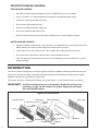

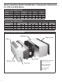
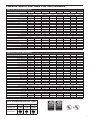


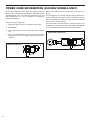
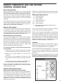
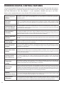
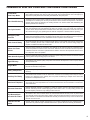
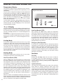
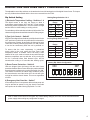

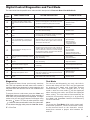
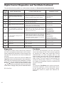
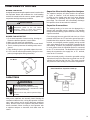
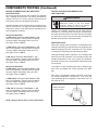
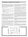
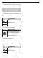
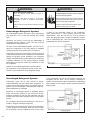
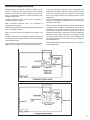
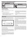
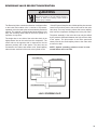
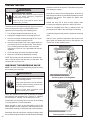


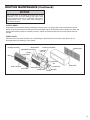

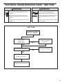

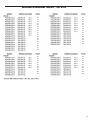
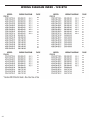

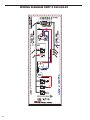
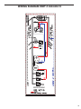
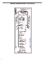
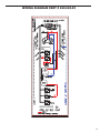
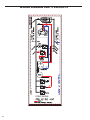
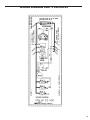

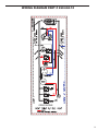

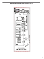
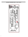
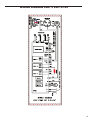

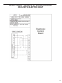
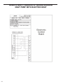
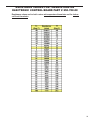


![FICON_AdminGd_v700[1].](http://vs1.manualzilla.com/store/data/005962703_1-207ddf39f2a91b852624dcbb8fd7d57f-150x150.png)